6
DRY WALL
PREPARATION
When installing on drywall or plaster, a 1 x
4 wood board must first be fastened to the
structural wall members (studs) behind the
drywall before mounting the track.
Using a ladder, tape measure and speed square,
find the center line position of the track by
adding 1-3/4" to the door height and measuring
up from the floor. Mark with a pencil.
To find end location of the track, measure 3"
over from opening mark location. (FIGURE 6)
NOTE: Mounting board to have same center as
track. End of mounting board may vary from
track end. See Step 7.
When installing with a standard 80" height
opening, the top trim will need to be removed
and the top of the side trim cut horizontally
along the height of the opening. (NOT SHOWN)
7
MARKING
MOUNTING HOLES
On a flat surface, center the track on the
mounting board (insure the track is straight
on the board). Mark locations of track
mounting holes onto board. (FIGURE 7)
8
ATTACHING
MOUNTING BOARD
Use the stud finder to find the framing
material (studs) behind the drywall. Mark
locations. (Remember to mark location so
that you will be able to see them when
mounting 1x4 board.)
Position the mounting board on the wall
ensuring it is level. Attach through drywall
into studs using #10 x 2-1/2 screws (2 per
stud location). Predrill with 1/8” drill bit.
Position screws so they do not interfere
with track mounting holes. (FIGURE 8)
INSTALLATION TIP: Locate and install one
screw at end of board first. This will hold
one end of the board so you can move the
free end and ensure the board is level as
you install the other #10 x 2-1/2” screws.
FIGURE 6. Locate the position of track and mounting board
1/8" (2" deep)
Drill depth
1 3/16"
(30 mm)
Framing material
(studs)
Track length
Door height + 1 3/4”
3” from
opening
3/8 (9.5 mm),
1/2” (12.7 mm)
gap under the
door
3/8” (9.5 mm),
1/2” (12.7 mm)
gap under the
door
Door height + 1 3/4”
3” from
opening
Track length
Solid wood
blocking
1/8" (2" deep)
Drill depth
1 3/16"
(30 mm)
Framing material
(studs)
Track length
Door height + 1 3/4”
3” from
opening
3/8 (9.5 mm),
1/2” (12.7 mm)
gap under the
door
3/8” (9.5 mm),
1/2” (12.7 mm)
gap under the
door
Door height + 1 3/4”
3” from
opening
Track length
Solid wood
blocking
FIGURE 7. Marking mounting holes on mounting board
FIGURE 8. Attaching mounting board to studs
1/8" (2" deep)
Drill depth
1 3/16"
(30 mm)
Framing material
(studs)
Track length
Door height + 1 3/4”
3” from
opening
3/8 (9.5 mm),
1/2” (12.7 mm)
gap under the
door
3/8” (9.5 mm),
1/2” (12.7 mm)
gap under the
door
Door height + 1 3/4”
3” from
opening
Track length
Solid wood
blocking
1/8" (2" deep)
Drill depth
1 3/16"
(30 mm)
Framing material
(studs)
Track length
Door height + 1 3/4”
3” from
opening
3/8 (9.5 mm),
1/2” (12.7 mm)
gap under the
door
3/8” (9.5 mm),
1/2” (12.7 mm)
gap under the
door
Door height + 1 3/4”
3” from
opening
Track length
Solid wood
blocking
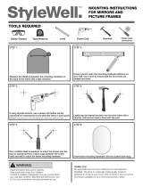
Tape Measure
Speed Square
Tape Measure
Pencil
Phillips
Screwdriver
Stud Finder
# 10 x 2-1/2
Wood Screws
Barn Door Installation Guide
BARN DOOR HARDWARE STRAIGHT STRAP KIT
©2018 Masonite International Corporation. HMD-18600
1-800-663-DOOR masonite.com
HMD-18600-Barn Door Installation-Instructions-SS-P2.indd 4 11/28/18 11:09 AM