Page is loading ...

CISCO SYSTEMS PUBLICATION HISTORY
170 W
EST TASMAN DR.
S
AN JOSE, CA, 95134 REV B.1 NOVEMBER 8, 2012
WWW.CISCO.COM
Cisco UCS C240 M3
High-Density
Rack Server
(Large Form Factor Hard
Disk Drive Model)

Cisco UCS C240 M3 High-Density Rack Server (Large Form Factor Hard Disk Drive Model)
2
CONTENTS
OVERVIEW . . . . . . . . . . . . . . . . . . . . . . . . . . . . . . . . . . . . . . . . . . . . . . . 3
DETAILED VIEWS . . . . . . . . . . . . . . . . . . . . . . . . . . . . . . . . . . . . . . . . . . . 3
Chassis Front View . . . . . . . . . . . . . . . . . . . . . . . . . . . . . . . . . . . . . . . . . . . . . . . . . . .3
Chassis Rear View . . . . . . . . . . . . . . . . . . . . . . . . . . . . . . . . . . . . . . . . . . . . . . . . . . .4
BASE SERVER STANDARD CAPABILITIES and FEATURES . . . . . . . . . . . . . . . . . 5
CONFIGURING the SERVER . . . . . . . . . . . . . . . . . . . . . . . . . . . . . . . . . . . . 8
STEP 1 VERIFY SERVER SKU . . . . . . . . . . . . . . . . . . . . . . . . . . . . . . . . . . . . . . . . . . . .9
STEP 2 SELECT CPU(s) . . . . . . . . . . . . . . . . . . . . . . . . . . . . . . . . . . . . . . . . . . . . . . 10
STEP 3 SELECT MEMORY . . . . . . . . . . . . . . . . . . . . . . . . . . . . . . . . . . . . . . . . . . . . . 12
STEP 4 SELECT RAID CONFIGURATION . . . . . . . . . . . . . . . . . . . . . . . . . . . . . . . . . . . . 17
STEP 5 SELECT HARD DISK DRIVES (HDDs) . . . . . . . . . . . . . . . . . . . . . . . . . . . . . . . . . 20
STEP 6 SELECT PCIe OPTION CARD(s) . . . . . . . . . . . . . . . . . . . . . . . . . . . . . . . . . . . . 22
STEP 7 ORDER OPTIONAL NETWORK CARD ACCESSORIES . . . . . . . . . . . . . . . . . . . . . . . . 25
STEP 8 ORDER POWER SUPPLIES . . . . . . . . . . . . . . . . . . . . . . . . . . . . . . . . . . . . . . . 28
STEP 9 SELECT AC POWER CORD(s) . . . . . . . . . . . . . . . . . . . . . . . . . . . . . . . . . . . . . 29
STEP 10 ORDER OPTIONAL REVERSIBLE CABLE MANAGEMENT ARM . . . . . . . . . . . . . . . . . 32
STEP 11 ORDER A TRUSTED PLATFORM MODULE . . . . . . . . . . . . . . . . . . . . . . . . . . . . . 33
STEP 12 ORDER CISCO FLEXIBLE FLASH SD CARD MODULE (OPTIONAL) . . . . . . . . . . . . . . . 34
STEP 13 ORDER USB 2.0 DRIVE (OPTIONAL) . . . . . . . . . . . . . . . . . . . . . . . . . . . . . . . . 35
STEP 14 SELECT OPERATING SYSTEM . . . . . . . . . . . . . . . . . . . . . . . . . . . . . . . . . . . . 36
STEP 15 SELECT OPERATING SYSTEM MEDIA KIT . . . . . . . . . . . . . . . . . . . . . . . . . . . . . 38
STEP 16 SELECT OPTIONAL VALUE-ADDED SOFTWARE . . . . . . . . . . . . . . . . . . . . . . . . . 39
STEP 17 SELECT SERVICE and SUPPORT LEVEL . . . . . . . . . . . . . . . . . . . . . . . . . . . . . . 40
OPTIONAL STEP - ORDER RACK(s) . . . . . . . . . . . . . . . . . . . . . . . . . . . . . . 44
OPTIONAL STEP - ORDER PDU . . . . . . . . . . . . . . . . . . . . . . . . . . . . . . . . . 45
SUPPLEMENTAL MATERIAL . . . . . . . . . . . . . . . . . . . . . . . . . . . . . . . . . . . 46
CHASSIS . . . . . . . . . . . . . . . . . . . . . . . . . . . . . . . . . . . . . . . . . . . . . . . . . . . . . . . . .46
CPUs and DIMMs . . . . . . . . . . . . . . . . . . . . . . . . . . . . . . . . . . . . . . . . . . . . . . . . . . . .47
Physical Layout . . . . . . . . . . . . . . . . . . . . . . . . . . . . . . . . . . . . . . . . . . . . . . . . 47
Memory Population Rules . . . . . . . . . . . . . . . . . . . . . . . . . . . . . . . . . . . . . . . . . 49
Recommended Memory Configuration . . . . . . . . . . . . . . . . . . . . . . . . . . . . . . . . . 50
Supported DIMM Populations . . . . . . . . . . . . . . . . . . . . . . . . . . . . . . . . . . . . . . . 52
Low-Voltage DIMM Considerations . . . . . . . . . . . . . . . . . . . . . . . . . . . . . . . . . . . . 53
RAID Summary . . . . . . . . . . . . . . . . . . . . . . . . . . . . . . . . . . . . . . . . . . . . . . . . . . . . .53
RACKS . . . . . . . . . . . . . . . . . . . . . . . . . . . . . . . . . . . . . . . . . . . . . . . . . . . . . . . . . .55
PDUs . . . . . . . . . . . . . . . . . . . . . . . . . . . . . . . . . . . . . . . . . . . . . . . . . . . . . . . . . . .57
KVM CABLE . . . . . . . . . . . . . . . . . . . . . . . . . . . . . . . . . . . . . . . . . . . . . . . . . . . . . . .58
Motherboard USB and SD Ports, and RAID Card Backup Locations . . . . . . . . . . . . . . . . . . .59
TECHNICAL SPECIFICATIONS . . . . . . . . . . . . . . . . . . . . . . . . . . . . . . . . . . 60
Dimensions and Weight . . . . . . . . . . . . . . . . . . . . . . . . . . . . . . . . . . . . . . . . . . . . . . .60
Power Specifications . . . . . . . . . . . . . . . . . . . . . . . . . . . . . . . . . . . . . . . . . . . . . . . .60
Environmental Specifications . . . . . . . . . . . . . . . . . . . . . . . . . . . . . . . . . . . . . . . . . . .62
Compliance Requirements . . . . . . . . . . . . . . . . . . . . . . . . . . . . . . . . . . . . . . . . . . . . .63

Cisco UCS C240 M3 High-Density Rack Server (Large Form Factor Hard Disk Drive Model)
OVERVIEW
3
OVERVIEW
The UCS C240 M3 rack server is designed for both performance and expandability over a wide range of
storage-intensive infrastructure workloads from big data to collaboration
Building on the success of the Cisco UCS C210 M2 rack server, the enterprise-class UCS C240 M3 server
further extends the capabilities of Cisco’s Unified Computing System portfolio in a 2U form factor with the
addition of the Intel® E5-2600 series processor family CPUs that deliver significant performance and
efficiency gains. In addition, the UCS C240 M3 server provides 24 DIMM slots, up to twelve 3.5-inch drives
and 4 x 1 GbE LOM to provide outstanding levels of internal memory and storage expandability along with
exceptional performance.
DETAILED VIEWS
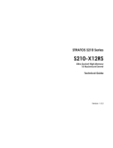
Chassis Front View
Figure 1 shows the Cisco UCS C240 M3 High-Density LFF Rack Server.
Figure 1 Chassis Front View
For more information about the KVM cable connection, see KVM CABLE, page 58.
1 KVM connector
(used with KVM cable that provides two USB,
one VGA, and one serial connector)
6 Temperature status LED
2 Asset tag (serial number) 7 Fan status LED
3 Drives (up to 12 3.5-inch hot-swappable
drives)
8 System status LED
4 Network link activity LED 9 Identification button/LED
5 Power supply status LED 10 Power button/power status LED
HDD 1
HDD 5
HDD 9
HDD 2
HDD 6
HDD 10
HDD 3
HDD 7
HDD 11
HDD 4
HDD 8
HDD 12
331825
4
5
6
7
8
10
9
3
2
1

Cisco UCS C240 M3 High-Density Rack Server (Large Form Factor Hard Disk Drive Model)
4
DETAILED VIEWS
Chassis Rear View
Figure 2 shows the external features of the rear panel.
Figure 2 Chassis Rear View
1 Power supplies (up to two) 7 One RJ-45 10/100/1000 Ethernet dedicated
management port
2 Standard-profile PCIe slot on riser 2:
PCIe 5—full-height, 3/4-length, x16 lane
width, x24 connector, GPU ready
8 USB 2.0 port
3 Low-profile PCIe slot on riser 2:
PCIe 4—half-height, 3/4-length, x8 lane
width, x16 connector, no NCSI
2
support
9 Quad 1-Gb Ethernet ports
(LAN1, LAN2, LAN3, and LAN4)
4 VGA video connector 10 Standard-profile PCIe slots on riser 1 (three):
PCIe 1—full-height, half-length, x8 lane
width, x8 connector
PCIe 2—full-height, half-length, x16 lane
width, x24 connector (supports Cisco Virtual
Interface Card (VIC))
PCIe 3—full-height, half-length, x8 lane
width, x16 connector
5 Serial connector (RJ-45) 11 Rear Identification button/LED
6 USB 2.0 port -
PSU1 PSU2
PCIe 1
PCIe 2
PCIe 3
PCIe 4
PCIe 5
4 98 107 1165
2 3
331826
1

Cisco UCS C240 M3 High-Density Rack Server (Large Form Factor Hard Disk Drive Model)
BASE SERVER STANDARD CAPABILITIES and FEATURES
5
BASE SERVER STANDARD CAPABILITIES and FEATURES
Table 1 lists the capabilities and features of the base server. Details about how to configure the server for
a particular feature or capability (for example, number of processors, disk drives, or amount of memory)
are provided in
CONFIGURING the SERVER, page 8.
Table 1 Capabilities and Features
Capability/Feature Description
Chassis Two rack unit (2RU) chassis
CPU One or two Intel® E5-2600 series processor family CPUs
Chipset Intel® C600 series chipset
Memory 24 slots for registered ECC DIMMs or load-reduced DIMMs (LRDIMMs)
NIC Embedded dual-port Intel i350 PCIe-based Gigabit Ethernet controller,
supporting the following:
■ Pre-Execution Boot (PXE boot)
■ iSCSI boot
Expansion slots Five PCIe slots (on two riser cards)
■ Riser 1 (PCIe slots 1, 2, and 3):
• One x16 PCIe Gen3 Slot, x24 extended connector, full-Height,
half-length
• Two x8 PCIe Gen3 slots full-height, x16 connector, half-length
■ Riser 2 (PCIe slots 4 and 5):
• One x16 PCIe Gen3 slot, full-height, (225W GPU Ready), x24
connector, three-quarter length
• One x8 PCIe Gen3 Slot, half-height, x16 connector, half-length
Internal storage devices Drives are installed into front-panel drive bays that provide hot-pluggable
access.
■ Large Form Factor (LFF) drives. The server can hold up to 12 3.5 inch
SAS or SATA hard disk drives (HDDs). The server uses a 12-drive
backplane with a SAS expander.
■ The server also contains one internal USB 2.0 port on the motherboard
that you can use with a USB thumb drive for additional storage
Cisco Flexible Flash
drives
The server supports one optional internal Cisco Flexible Flash drive (SD
card).
■ The SD card is pre-loaded with four virtual drives. The four virtual
drives contain, respectively, the Cisco Server Configuration Utility, the
Cisco Host Upgrade Utility, the Cisco C-Series server drivers set, and a
blank virtual drive on which you can install an OS or a hypervisor.
■ 4 GB is available for general use

Cisco UCS C240 M3 High-Density Rack Server (Large Form Factor Hard Disk Drive Model)
6
BASE SERVER STANDARD CAPABILITIES and FEATURES
Storage controller ■ 2008M-8i Mezzanine Cards - two versions
• Cisco UCSC RAID SAS 2008M-8i Mezzanine Card supports up to 16
SAS/SATA drives (limited to 12 drives in the C240 M3 LFF chassis)
supporting RAID 0, 1, 10, 5, and 50. SAS and SATA drives can be
mixed. This card has a product ID (PID) of UCSC-RAID-11-C240.
• Cisco UCSC RAID SAS 2008M-8i Mezzanine Card supports up to 16
SAS/SATA drives (limited to 12 drives in the C240 M3 LFF chassis)
supporting RAID 0, 1, and 10. SAS and SATA drives can be mixed. This
card has a product ID (PID) of UCSC-RAID-MZ-240.
■ Plug-in PCIe Cards
• LSI MegaRAID SAS 9266-8i 8-port plug-in PCIe RAID controller card
(occupies a half-height PCIe slot) supporting RAID levels 0, 1, 10, 5,
6, 50, 60 and up to 16 internal SAS or SATA drives (limited to 12 drives
in the C240 M3 LFF chassis). SAS and SATA drives can be mixed.
• LSI MegaRAID SAS 9266CV-8i 8-port plug-in PCIe RAID controller card,
supporting RAID 0, 1, 10, 5, 6, 50, and 60 and up to 16 internal SAS or
SATA drives (limited to 12 drives in the C240 M3 LFF chassis). SAS and
SATA drives can be mixed.
Video The Emulex Pilot 3 Integrated Baseboard Management Controller provides
video:
■ Matrox G200e video controller
■ Integrated 2D graphics core with hardware acceleration
■ Supports all display resolutions up to 1920 x 1200 x 16 bpp resolution at
60 Hz
■ 24-bit color depth for all resolutions less than 1600x1200
■ Up to 256 MB video memory
Interfaces Rear panel
■ One RJ-45 10/100/1000 Ethernet management port, using Cisco
Integrated Management Controller (CIMC) firmware
■ Four 1-Gb LOM ports
■ One RJ45 serial port connector
■ Two USB 2.0 port connectors
■ One DB15 VGA connector
■ Various PCIe card ports (dependent on which cards are installed)
• Converged Network Adapter (CNA) ports
• Network Interface Card (NIC) ports
• Host Bus Adapter (HBA) ports
Front panel
■ One KVM console connector (supplies two USB 2.0, one VGA, and one
serial connector)
Front Panel A front panel controller provides status indications and control buttons
Capability/Feature Description

Cisco UCS C240 M3 High-Density Rack Server (Large Form Factor Hard Disk Drive Model)
BASE SERVER STANDARD CAPABILITIES and FEATURES
7
Power subsystem Two power supplies are required (either 650 W or 1200 W).
Redundant as 1 + 1.
Fans Chassis:
■ Six hot-swappable fans for front-to-rear cooling
Power supply:
■ Each power supply is equipped with a fan.
Integrated management
processor
Cisco Integrated Management Controller (CIMC) firmware.
Depending on your CIMC settings, the CIMC can be accessed through the 1-Gb
Ethernet dedicated management port, the 1-Gb Ethernet LOM ports, or a
Cisco P81E or Cisco 1225 virtual interface card (VIC).
Capability/Feature Description

Cisco UCS C240 M3 High-Density Rack Server (Large Form Factor Hard Disk Drive Model)
8
CONFIGURING the SERVER
CONFIGURING the SERVER
Follow these steps to configure the Cisco UCS C240 M3 High-Density LFF Rack Server:
■ STEP 1 VERIFY SERVER SKU, page 9
■ STEP 2 SELECT CPU(s), page 10
■ STEP 3 SELECT MEMORY, page 12
■ STEP 4 SELECT RAID CONFIGURATION, page 17
■ STEP 5 SELECT HARD DISK DRIVES (HDDs), page 20
■ STEP 6 SELECT PCIe OPTION CARD(s), page 22
■ STEP 7 ORDER OPTIONAL NETWORK CARD ACCESSORIES, page 25
■ STEP 8 ORDER POWER SUPPLIES, page 28
■ STEP 9 SELECT AC POWER CORD(s), page 29
■ STEP 10 ORDER OPTIONAL REVERSIBLE CABLE MANAGEMENT ARM, page 32
■ STEP 11 ORDER A TRUSTED PLATFORM MODULE, page 33
■ STEP 12 ORDER CISCO FLEXIBLE FLASH SD CARD MODULE (OPTIONAL), page 34
■ STEP 13 ORDER USB 2.0 DRIVE (OPTIONAL), page 35
■ STEP 14 SELECT OPERATING SYSTEM, page 36
■ STEP 15 SELECT OPERATING SYSTEM MEDIA KIT, page 38
■ STEP 16 SELECT OPTIONAL VALUE-ADDED SOFTWARE, page 39
■ STEP 17 SELECT SERVICE and SUPPORT LEVEL, page 40
■ OPTIONAL STEP - ORDER RACK(s), page 44
■ OPTIONAL STEP - ORDER PDU, page 45

Cisco UCS C240 M3 High-Density Rack Server (Large Form Factor Hard Disk Drive Model)
CONFIGURING the SERVER
9
STEP 1 VERIFY SERVER SKU
Verify the product ID (PID) of the server as shown in Table 2.
The Cisco C240 M3 server:
■ Includes one tool-less rail kit, adjustable from 26 inches (660 mm) to 36 inches (914 mm)
■ Does not include power supply, CPU, memory, hard disk drives (HDDs), SD card, or plug-in
PCIe cards.
Table 2 PID of the C240 M3 High-Density LFF Rack Base Server
Product ID (PID) Description
UCSC-C240-M3L UCS C240 M3 LFF, no CPU, memory, HDD, power supply, SD card, or PCIe cards,
with rail kit
NOTE: Use the steps on the following pages to configure the server with
the components that you want to include.

Cisco UCS C240 M3 High-Density Rack Server (Large Form Factor Hard Disk Drive Model)
10
CONFIGURING the SERVER
STEP 2 SELECT CPU(s)
The standard CPU features are:
■ Intel E5-2600 series processor family CPU
■ Intel® C600 series chipset
■ Cache size of 10, 15, or 20 MB
Select CPUs
The available CPUs are listed in Table 3.
Table 3 Available Intel CPUs: E5-2600 Series Processor Family CPUs
Product ID (PID)
Intel
Number
Clock
Freq
(GHz)
Power
(W)
Cache
Size
(MB)
Cores QPI
Highest DDR3
DIMM Clock
Support (MHz)
1
Notes . . .
1. If higher or lower speed DIMMs are selected than what is shown in the table for a given CPU, the DIMMs will be
clocked at the lowest common denominator of CPU clock and DIMM clock.
UCS-CPU-E5-2690 E5-2690 2.90 135 20 8 8 GT/s 1600
UCS-CPU-E5-2680 E5-2680 2.70 130 20 8 8 GT/s 1600
UCS-CPU-E5-2670 E5-2670 2.60 115 20 8 8 GT/s 1600
UCS-CPU-E5-2667 E5-2667 2.90 130 15 6 8 GT/s 1600
UCS-CPU-E5-2665 E5-2665 2.40 115 20 8 8 GT/s 1600
UCS-CPU-E5-2660 E5-2660 2.20 95 20 8 8 GT/s 1600
UCS-CPU-E5-2650 E5-2650 2.00 95 20 8 8 GT/s 1600
UCS-CPU-E5-2650L E5-2650L 1.80 70 20 8 8 GT/s 1600
UCS-CPU-E5-2643 E5-2643 3.30 130 10 4 8 GT/s 1600
UCS-CPU-E5-2640 E5-2640 2.50 95 15 6 7.2 GT/s 1333
UCS-CPU-E5-2630 E5-2630 2.30 95 15 6 7.2 GT/s 1333
UCS-CPU-E5-2630L E5-2630L 2.00 60 15 6 7.2 GT/s 1333
UCS-CPU-E5-2620 E5-2620 2.00 95 15 6 7.2 GT/s 1333
UCS-CPU-E5-2609 E5-2609 2.40 80 10 4 6.4 GT/s 1066

Cisco UCS C240 M3 High-Density Rack Server (Large Form Factor Hard Disk Drive Model)
CONFIGURING the SERVER
11
Approved Configurations
(1) 1-CPU configurations:
■ Select any one CPU listed in Table 3.
(2) 2-CPU Configurations:
■ Select two identical CPUs from any one of the rows of Table 3 on page 10.
Caveats
■ You can select either one processor or two identical processors.
■ For optimal performance, select DIMMs with the highest clock speed for a given processor
(see
Table 3 on page 10). If you select DIMMs whose speeds are lower or higher than that
shown in the tables, suboptimal performance will result.

Cisco UCS C240 M3 High-Density Rack Server (Large Form Factor Hard Disk Drive Model)
12
CONFIGURING the SERVER
STEP 3 SELECT MEMORY
The standard memory features are:
■ DIMMs
— Clock speed: 1333 or 1600 MHz
— Ranks per DIMM: 1, 2, or 4
— Operational voltage: dual voltage capable (1.5 V or 1.35 V)
— Registered ECC DDR3 DIMMS (RDIMMS) and load-reduced DIMMs (LRIMMs)
■ Memory is organized with four memory channels per CPU, with up to three DIMMs per
channel, as shown in
Figure 3.
Figure 3 C240 M3 LFF Memory Organization

Cisco UCS C240 M3 High-Density Rack Server (Large Form Factor Hard Disk Drive Model)
CONFIGURING the SERVER
13
Select DIMMs and Memory Mirroring
Select the memory configuration and whether or not you want the memory mirroring option.
The available memory DIMMs and mirroring option are listed in
Table 4.
Approved Configurations
(1) 1-CPU configuration without memory mirroring:
■ Select from 1 to 12 DIMMs. Refer to Memory Population Rules, page 49, for more detailed
information.
(2) 1-CPU configuration with memory mirroring:
NOTE: When memory mirroring is enabled, the memory subsystem simultaneously
writes identical data to two channels. If a memory read from one of the channels
returns incorrect data due to an uncorrectable memory error, the system
automatically retrieves the data from the other channel. A transient or soft error in
one channel does not affect the mirrored data, and operation continues unless there
is a simultaneous error in exactly the same location on a DIMM and its mirrored
DIMM. Memory mirroring reduces the amount of memory available to the operating
system by 50% because only one of the two populated channels provides data.
Table 4 Available DDR3 DIMMs
Product ID (PID) PID Description Voltage
Ranks/
DIMM
DIMM Options
UCS-ML-1X324RY-A 32GB DDR3-1600-MHz LR DIMM/PC3-12800/quad rank/x4/1.35v 1.35 V 4
UCS-MR-1X162RY-A 16GB DDR3-1600-MHz RDIMM/PC3-12800/2R/x4/1.35v 1.35 V 2
UCS-MR-1X162RX-A 16GB DDR3-1333-MHz RDIMM/PC3-10600/2R/x4/1.35v 1.35 V 2
UCS-MR-1X082RY-A 8GB DDR3-1600-MHz RDIMM/PC3-12800/2R/x4/1.35v 1.35 V 2
UCS-MR-1X082RX-A 8GB DDR3-1333-MHz RDIMM/PC3-10600/2R/x4/1.35v 1.35 V 2
UCS-MR-1X041RY-A 4GB DDR3-1600-MHz RDIMM/PC3-12800/single rank/x4/1.35v 1.35 V 1
UCS-MR-1X041RX-A 4GB DDR3-1333-MHz RDIMM/PC3-10600/single rank/x4/1.35v 1.35 V 1
Memory Mirroring Option
N01-MMIRROR Memory mirroring option

Cisco UCS C240 M3 High-Density Rack Server (Large Form Factor Hard Disk Drive Model)
14
CONFIGURING the SERVER
■ Select 2, 4, 6, 8, 10, or 12 identical DIMMs. The DIMMs will be placed by the factory as shown
in the following table.
■ Select the memory mirroring option (N01-MMIRROR) as shown in Table 4 on page 13.
(3) 2-CPU configuration without memory mirroring:
■ Select from 1 to 12 DIMMs per CPU. Refer to Memory Population Rules, page 49, for more
detailed information.
Total
Number
of
DIMMs
CPU 1 DIMM Placement in Channels
(for
identical DIMMs)
Blue Slot
(Slot 1)
Black Slot
(Slot 2)
Black Slots
(Slot 3)
2 (A1, B1) — —
4 (A1,B1); (C1,D1) — —
6 (A1,B1); (C1,D1) (A2,B2) —
8 (A1,B1); (C1,D1) (A2,B2); (C2,D2) —
10
1
Notes . . .
1. This configuration cannot be implemented with quad-rank DIMMs (the 32 GB DIMM). You can have
only 1 or 2 DIMMs per channel when using quad-rank DIMMs.
(A1,B1); (C1,D1) (A2,B2); (C2,D2) (A3,B3)
12
1
(A1,B1); (C1,D1) (A2,B2); (C2,D2) (A3,B3); (C3,D3)

Cisco UCS C240 M3 High-Density Rack Server (Large Form Factor Hard Disk Drive Model)
CONFIGURING the SERVER
15
(4) 2-CPU configuration with memory mirroring:
■ Select 2, 4, 6, 8, 10, or 12 identical DIMMs per CPU. The DIMMs will be placed by the factory
as shown in the following table.
■ Select the memory mirroring option (N01-MMIRROR) as shown in Table 4 on page 13.
Number
of
DIMMs
per CPU
CPU 1 DIMM Placement in Channels
(for
identical DIMMs)
CPU 2 DIMM Placement in Channels
(for
identical DIMMs)
Blue Slots Black Slots Black Slots Blue Slots Black Slots Black Slots
2 (A1, B1) (E1, F1)
4 (A1,B1);
(C1,D1)
— — (E1,F1);
(G1,H1)
— —
6 (A1,B1);
(C1,D1)
(A2,B2) — (E1,F1);
(G1,H1)
(E2,F2) —
8 (A1,B1);
(C1,D1)
(A2,B2);
(C2,D2)
— (E1,F1);
(G1,H1)
(E2,F2);
(G2,H2)
—
10
1
Notes . . .
1. This configuration cannot be implemented with quad-rank DIMMs (the 32 GB DIMM). You can have only 1 or 2
DIMMs per channel when using quad-rank DIMMs.
(A1,B1);
(C1,D1)
(A2,B2);
(C2,D2)
(A3,B3) (E1,F1);
(G1,H1)
(E2,F2);
(G2,H2)
(E3,F3)
12
1
(A1,B1);
(C1,D1)
(A2,B2);
(C2,D2)
(A3,B3);
(C3,D3)
(E1,F1);
(G1,H1)
(E2,F2);
(G2,H2)
(E3,F3);
(G3,H3)
NOTE: System performance is optimized when the DIMM type and quantity are equal
for both CPUs.

Cisco UCS C240 M3 High-Density Rack Server (Large Form Factor Hard Disk Drive Model)
16
CONFIGURING the SERVER
Caveats
■ The server supports 1, 2, or 3 DIMMs per channel for single- or dual-rank RDIMMs.
■ The server supports 1, 2, or 3 DIMMs per channel for quad-rank DIMMs.
■ The server supports registered DIMMs (RDIMMs) or load-reduced DIMMS (LRDIMMs), however,
do not mix RDIMMs and LRDIMMs in a server.
■ When using mirroring, DIMMs must be installed in identical pairs across paired DDR3 buses.
That is, mirrored pairs in channels A and B must be identical and pairs in channels C and D
must be identical. However, the DIMMs used in channels A and B and in C and D can be
different.
■ UDIMMs and non-ECC DIMMs are not supported.
■ Memory mirroring reduces the amount of available memory by 50% (quantity of DIMMs must
be even for mirroring).
■ When single- and dual-rank DIMMs are populated for 2DPC, always populate the dual-rank
DIMM in the blue DIMM slot first (blue slot) and the single-rank DIMM last in the black DIMM
slots (only the 4GB DIMMs are single-rank).
■ By default, all DIMMs run at 1.35 V, which yields 1333-MHz memory speeds. To run the
memory DIMMS at 1600 MHz, you need to go into the BIOS or set the policy with UCSM
(service profile) to run in Performance Mode. This forces the DIMMs to operate at 1.5 V and
yields 1600-MHz speeds, provided:
— The DIMMs are 1600-MHz devices and the DIMM type is RDIMM
— The CPUs chosen support 1600-MHz operation
— There are less than 3 DIMMs per channel
■ With 3 DIMMs populated per channel, memory always runs at 1.5 V regardless if the BIOS
setting is low-power mode (1.35 V) or performance mode (1.5 V).
For more information regarding memory, see CPUs and DIMMs, page 47.
NOTE: Memory speed is limited to 1066 MHz for 3 DPC configurations.
NOTE: 32 GB LRDIMMs run at a maximum speed of 1333 MHz for 1DPC and 2DPC even
though their specified maximum speed is 1600 MHz.

Cisco UCS C240 M3 High-Density Rack Server (Large Form Factor Hard Disk Drive Model)
CONFIGURING the SERVER
17
STEP 4 SELECT RAID CONFIGURATION
The RAID controller choices are:
■ Mezzanine RAID controller cards
■ Plug-in PCIe RAID controller cards
Cisco can provide factory-configured RAID systems depending on the RAID controller chosen and
the number of drives ordered. Factory-configured RAID options are listed with each RAID card
description.
Select RAID Options
Select as follows:
■ One mezzanine RAID controller (see Table 5), or
■ One PCIe RAID controller card (see Table 6 on page 18)
NOTE: The number of RAID groups (logical drives/virtual drives) supported per
controller is as follows:
■ Cisco UCSC RAID SAS 2008M-8i Mezzanine Card = 16 drives
■ LSI MegaRAID SAS 9266-8i/9266CV-8i RAID controller cards = 64 drives
Table 5 Available Mezzanine Card RAID Options
Product ID (PID) PID Description
RAID Controllers
UCSC-RAID-11-C240 Cisco UCSC RAID SAS 2008M-8i Mezzanine Card (RAID 0, 1, 10, 5, and 50
supported)
■ Supports up to 12 internal SAS or SATA drives (with the 12-drive backplane
plus SAS expander). SAS and SATA drives can be mixed.
■ Factory-configured RAID options available: RAID 0, 1, 10, and 5 (see the
RAID PIDs section in this table)
■ No data cache backup
UCSC-RAID-MZ-240 Cisco UCSC RAID SAS 2008M-8i Mezzanine Card (RAID 0, 1, 10 supported)
■ Supports up to 12 internal SAS or SATA drives (with the 12-drive backplane
plus SAS expander). SAS and SATA drives can be mixed.
■ Factory-configured RAID options available: RAID 0, 1, and 10 (see the RAID
PIDs section in this table)
■ No data cache backup

Cisco UCS C240 M3 High-Density Rack Server (Large Form Factor Hard Disk Drive Model)
18
CONFIGURING the SERVER
Table 6 Available Plug-In PCIe Card RAID Options
Product ID (PID) PID Description
RAID Controllers
UCS-RAID-9266NB LSI MegaRAID SAS 9266-8i RAID controller card with no data cache backup
(RAID 0, 1, 10, 5, 6, 50, and 60 supported)
■ Installed by default in the half-height PCIe slot (slot 2)
■ Supports up to 16 internal SAS and/or SATA drives (limited to 12 drives for
the C240 M3 LFF chassis). SAS and SATA drives can be mixed.
■ Includes 1 GB of write cache
■ Factory-configured RAID options available: RAID 0, 1, 10, 5, and 6 (see the
RAID PIDs section in this table)
UCS-RAID-9266CV LSI MegaRAID SAS 9266CV-8i RAID controller card with data cache backup (RAID
0, 1, 10, 5, 6, 50, 60)
■ Supports up to 16 internal SAS or SATA drives (limited to 12 drives for the
C240 M3 LFF chassis). SAS and SATA drives can be mixed.
■ Includes a 1 GB Transportable Memory Module (TMM) and SuperCap power
module for data cache backup
■ Factory-configured RAID options available: RAID 0, 1, 10, 5, and 6 (see the
RAID PIDs section in this table)
Super Capacitor Option
UCS-RAID-CV-SC= LSI CacheVault Power Module for SAS 9266CV-8i
RAID Configuration Options
R2XX-RAID0 Factory preconfigured RAID striping option
Enable RAID 0 Setting. Requires a minimum of one hard drive.
R2XX-RAID1 Factory preconfigured RAID mirroring option
Enable RAID 1 Setting. Requires exactly two drives with the same size, speed,
capacity.
R2XX-RAID5 Factory preconfigured RAID option
Enable RAID 5 Setting. Requires a minimum of three drives of the same size,
speed, capacity.
R2XX-RAID6 Factory preconfigured RAID option
Enable RAID 6 Setting. Requires a minimum of four drives of the same size,
speed, capacity.
R2XX-RAID10 Factory preconfigured RAID option
Enable RAID 10 Setting. Requires a even number of drives (minimum of four
drives) of the same size, speed, capacity.
NOTE: Although RAID levels 50 and 60 are not orderable from the factory, they are
supported for selected controllers as shown in Table 6

Cisco UCS C240 M3 High-Density Rack Server (Large Form Factor Hard Disk Drive Model)
CONFIGURING the SERVER
19
Approved Configurations
(1) 1-CPU Configurations
Mezzanine cards are not supported for 1-CPU configurations, Therefore, only the following RAID
controllers are supported for single-CPU configurations:
■ LSI MegaRAID SAS 9266-8i
■ LSI MegaRAID SAS 9266CV-8i
(2) 2-CPU Configurations
■ Select a mezzanine card RAID option from Table 5 or one of the RAID controllers from
Table 6. You may also select an appropriate optional RAID configuration listed in Table 6.
Caveats
■ The mezzanine controller is not available for 1-CPU configurations.
■ If you choose a mezzanine card RAID controller, all five of the PCIe card slots are still
available for adding optional PCIe cards.
■ The optional PCIe RAID controllers are all half-height PCIe cards. If you choose one of these
cards, four PCIe card slots will be available for adding an optional PCIe card.
■ Note that when just one CPU is populated, only a single Cisco UCS P81E or Cisco 1225 Virtual
Interface Card (VIC) card is supported and it must be installed in the full-height PCIe slot
(slot 2) on riser 1. So take this into account when populating RAID controller cards. When
two CPUs are populated, two VIC cards are supported (either the Cisco UCS P81E or Cisco
VIC 1225 or both). One can be installed in slot 2 of riser 1 and one in slot 5 of riser 2. The
primary slot for a VIC card is slot 2. If you have only one of these cards, install it in slot 2.
■ You can choose only one RAID controller (a plug-in PCIe RAID controller or a mezzanine card
RAID controller).
■ You can choose an optional RAID configuration (RAID 0, 1, 5, 6, or 10), which is
preconfigured at the factory. The RAID level you choose must be an available RAID choice for
the controller selected. RAID levels 50 and 60 are supported, although they are not available
as configuration options.
NOTE: No RAID option can be chosen if you have no drives

Cisco UCS C240 M3 High-Density Rack Server (Large Form Factor Hard Disk Drive Model)
20
CONFIGURING the SERVER
STEP 5 SELECT HARD DISK DRIVES (HDDs)
The standard disk drive features are:
■ 3.5-inch large form factor
■ Hot-pluggable
■ Sled-mounted
Select Drives
The available drives are listed in Table 7.
Table 7 Available Hot-Pluggable Sled-Mounted HDDs
Product ID (PID) PID Description
Drive
Type
Capacity
HDDs
UCS-HDD3TI2F214 3 TB SAS 7.2K RPM 3.5 inch HDD SAS 3 TB
UCS-HDD2TI2F213 2 TB SAS 7.2K RPM 3.5 inch HDD SAS 2 TB
UCS-HDD1TI2F212 1 TB SAS 7.2K RPM 3.5 inch HDD SAS 1 TB
UCS-HDD600GI2F210 600 GB SAS 15K RPM 3.5 inch HDD SAS 600 GB
UCS-HDD450GI2F209 450 GB SAS 15K RPM 3.5 inch HDD SAS 450 GB
UCS-HDD500GI1F211 500 GB SATA 7.2K RPM 3.5 inch HDD SAS 500 GB
UCS-HDD300GI2F208 300 GB SAS 15K RPM 3.5 inch HDD SAS 300 GB
NOTE: No RAID option can be chosen if you have no drives
/