
X7503242504
X750009914
04/12
WARNING
Users of this equipment risk injury to themselves and others if the unit is used improperly
and/or safety precautions are not followed. ECHO provides an operator’s manual and a
safety manual. Both must be read and understood for proper and safe operation. Failure to
do so could result in serious injury.
Chain Saw
Instruction Manual
MODELS : CS-330T
CS-360T

2
Rules foR safe opeRation
A. Kickback Safety Precautions for Chain Saw Users
Copyright© 2012 By Echo, Incorporated
All Rights Reserved.
B. Other Safety Precautions
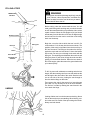
1. Do not operate a chain saw with one hand! Serious
injury to the operator, helpers, bystanders, or any com-
bination of these persons may result from one-handed
operation. A chain saw is intended for two-handed
use.
2. Do not operate a chain saw when you are fatigued.
3. Use safety footwear; snug-tting clothing; protective
gloves; and eye, hearing and head protection devices.
Keep long hair away from engine and air intake. Retain
hair with cap or net.
4. Use caution when handling fuel. Move the chain saw at
least 3 m (10 feet) from the fueling point before starting
the engine.
5. Do not allow other persons to be near the chain saw
when starting or cutting with the chain saw. Keep by-
standers and animals out of the work area.
6. Do not start cutting until you have a clear work area,
secure footing, and a planned retreat path from the
falling tree.
7. Keep all parts of your body away from the saw chain
when the engine is running.
8. Before you start the engine, make sure that the saw
chain is not contacting anything.
9. Carry the chain saw with the engine stopped, the guide
bar and saw chain to the rear, and the mufer away
from your body.
10. Do not operate a chain saw that is damaged, improperly
adjusted, or not completely and securely assembled.
Be sure that the saw chain stops moving when the
throttle control trigger is released.
11. Shut off the engine before setting the chain saw
down.
12. Use extreme caution when cutting small size brush
and saplings because slender material may catch the
saw chain and be whipped toward you or pull you off
balance.
13. When cutting a limb that is under tension, be alert for
spring back so that you will not be struck when the
tension in the wood bers is released.
WARNING!
KICKBACK may occur when the nose or tip of the guide
bar touches an object, or when the wood closes in and
pinches the saw chain in the cut.
Tip contact in some cases may cause a lightning fast
reverse REACTION, Kicking the guide bar up and back
towards the operator. Pinching the saw chain along the
top of the guide bar may push the guide bar rapidly back
towards the operator. Either of these reactions may cause
you to lose control of the saw which could result in serious
personal injury.
The Kick Guard
®
device is not installed on the guide bar
when you purchase your ECHO chain saw. The Kick Guard
®
can be used in a majority of cutting operations, and is
especially recommended for beginners, homeowners, or
chain saw novices. Most cutting operations can be ac-
complished with the Kick Guard
®
in place.
Do not rely exclusively upon the safety devices built into
your saw. As a chain saw user, you should take several
steps to keep your cutting jobs free from accident or in-
jury.
1. With a basic understanding of kickback, you can reduce
or eliminate the element of surprise. Sudden surprise
contributes to accidents.
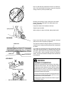
2. Keep a good rm grip on the saw with both hands, the
right hand on the rear handle, and the left hand on the
front handle, when the engine is running. Use a rm
grip with thumbs and ngers encircling the chain saw
handles. A rm grip will help you reduce kickback and
maintain control of the saw. Don’t’ let go.
3. Make sure that the area in which you are cutting is free
from obstructions. Do not let the nose of the guide bar
contact a log, branch, or any other obstruction which
could be hit while you are operating the saw.
4. Cut at high engine speeds.
5. Do not overreach or cut above shoulder height.
6. Follow manufacturer’s sharpening and maintenance
instructions for the saw chain.
7. Only use replacement bars and chains, or the equiva-
lent, specied by the manufacturer.

3
14. Keep the handles dry, clean, and free of oil or fuel
mixture.
15. Operate the chain saw only in well-ventilated areas.
16. Do not operate a chain saw in a tree unless you have
been specically trained to do so.
17. All chain saw service, other than the items listed in
the Instruction Manual maintenance instructions,
should be performed by competent chain saw service
personnel. (For example, if improper tools are used
to remove the ywheel or if an improper tool is used
to hold the ywheel in order to remove the clutch,
structural damage to the ywheel could occur and
could subsequently cause the ywheel to burst.)
18. When transporting your chain saw, use the appropri-
ate guide bar scabbard.
19. Spark arrestor mufers approved to SAE Standard
J335b are Standard on ECHO Chain saws to reduce
the possibility of forest res. Do not operate the chain
saw with a loose or defective mufer. Do not remove
the spark arrestor screen.
WARNING
Using improper replacement components or removing safety devices may result in serious or fatal injury.
WARNING
• During operation, the mufer or catalytic mufer and surrounding cover become hot.
• Never suspend the saw on a lanyard with the engine running.
• Always use the saw from the right-hand side of your body – NEVER from the left side.
• Always wear proper safety clothing to protect your lower body from sharp saw chain and
hot mufer.
• Always keep exhaust area clear of ammable debris during transportation or when storing,
otherwise serious property damage or personal injury may result.
WARNING
Moving parts can amputate ngers or cause severe injuries. Keep hands, clothing and loose objects away from
all openings.
• ALWAYS stop engine, disconnect spark plug, and make sure all moving parts have come to a complete stop
before removing obstructions, clearing debris, or servicing unit.
• DO NOT start or operate unit unless all guards and protective covers are properly assembled to unit.
• NEVER reach into any opening while the engine is running. Moving parts may not be visible through openings.
WARNING
Check fuel system for leaks due to fuel tank damage, especially if the unit is dropped. If damage or leaks are
found, do not use unit, otherwise serious personal injury or property damage may occur. Have unit repaired by an
authorized servicing dealer before using.

4
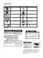
WARNING
The safety alert symbol accompanied by
the word “WARNING” calls attention to an
act or condition which CAN lead to serious
personal injury or death if not avoided.
CIRCLE AND SLASH SYMBOL
This symbol means the specic action
shown is prohibited. Ignoring these
prohibitions can result in serious or
fatal injury.
CAUTION
The safety alert symbol accompanied by
the word “CAUTION” calls attention to an
act or condition which may lead to minor or
moderate personal injury if not avoided.
NOTE
This enclosed message provides tips for use,
care and maintenance of the unit.
IMPORTANT
The enclosed message provides information
necessary for the protection of the unit.
DANGER
The safety alert symbol accompanied by
the word “DANGER” calls attention to an
act or condition which WILL lead to serious
personal injury or death if not avoided.
sYMBols anD siGns
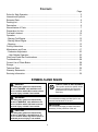
Contents
Page
Rules for Safe Operation ..................................................................................................2
International Symbols .......................................................................................................5
Emission Data ..................................................................................................................6
Packing List ......................................................................................................................6
Description........................................................................................................................6
Nomenclature of Parts ......................................................................................................7
Preparation for Use ..........................................................................................................8
Fuel and Lubricant ..........................................................................................................10
Operation ........................................................................................................................ 11
- Starting Cold Engine ....................................................................................................12
- Starting Warm Engine ..................................................................................................13
- Stopping .......................................................................................................................13
Cutting Instructions .........................................................................................................14
Maintenance and Care ...................................................................................................17
- Carburetor Adjustment .................................................................................................23
- High Altitude Operation ..............................................................................................23
Chain and Guide Bar Combinations ............................................................................... 24
Troubleshooting .............................................................................................................. 28
Correct Use of Chain Brake............................................................................................28
Storage ...........................................................................................................................29
Technical Data ................................................................................................................30
Warranty Statements ...................................................................................................... 31
Servicing Information ......................................................................................................36

5
Carburetor adjustment
- Idle speed
Carburetor adjustment
- High speed mixture
Carefully read the Instruction
manual
Wear eyes, ears and head
protection
Carburetor adjustment
- Low speed mixture
Oil and gasoline mixture
Symbol form/shape Symbol description/application Symbol form/shape Symbol description/application
Chain oiler adjustmentChain brake operation
Chain oil pump
Chain oil ll
Emergency stop
Choke control “Cold Start”
position (choke closed)
STOP
SYMBOL FORM
Locate these safety decals on your unit. Make sure
the decals are legible and that you understand and
follow the instructions on them. If a decal can-
not be read, a new one can be ordered from your
ECHO dealer.
DECALS
REPLACEMENT BAR AND
CHAIN
Note:There may be other replace-
ment components for achieving
kickback protection. For details,
please refer to the chain and
bar combination sheet shown in
the instruction manual.
GUIDE BAR* CHAIN*
PART NO. TYPE LINKS
12” 12AOED3745 OREGON 91VG 45
14” 14AOED3752 OREGON 91VG 52
16” 16AOED3757 OREGON 91VG 57
Chain brake must be unlocked before removing or
installing clutch cover. Improper cover installation can
result in serious injury and cause severe damage to
saw.
El freno de la cadena debe ser desbloqueado antes
de remover o de instalar la cubierta del embrague. La
instalación incorrecta de la cubierta puede dar lugar a
lesión seria y causar daño severo a la sierra.

6
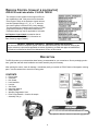
DesCRiption
The ECHO product you purchased has been factory pre-assembled for your convenience. Due to packaging restric-
tions, guide bar and saw chain installation and other assembly may be necessary.
After opening the carton, check for damage. Immediately notify your retailer or ECHO Dealer of damaged or missing
parts. Use the contents list to check for missing parts.
Contents
1 - Power Head
1 - Guide Bar
1 - Kick Guard
1 - Hex Head Bolt
1 - Hex Nut
1 - Saw Chain
1 - Instruction Manual
1 - Safety Manual
1 - Warranty Registration Card
1 - Echo Power BlendX
TM
2-stroke oil sample
- Assembly Tool (s)
An Emission Control Label is located on the en-
gine. (This is an EXAMPLE ONLY, information on
label varies by engine FAMILY).
eMission ContRol (exhaust & evapoRative)
EPA 2010 and Later and/or C.A.R.B. TIER III
PRODUCT EMISSION DURABILITY (EMISSION COMPLIANCE PERIOD)
The 300 hour emission compliance period is the time span selected by the manufacturer certifying the
engine emissions output meets applicable emissions regulations, provided that approved maintenance
procedures are followed as listed in the Maintenance Section of this manual.
The emission control system for the engine is EM (en-
gine modication) and, if the second to last character
of the Engine Family on the Emission Control Informa-
tion label (sample below) is “C”, “K”, or “T”, the emis-
sion control system is EM and TWC (3-way catalyst).
The fuel tank/fuel line emission control system is EVAP
(evaporative emissions). Evaporative emissions for
California models may only be applicable to fuel tanks.

7
1. Hand guard
(Chain brake actuating lever)
2. Ignition/Choke Lever
3. Throttle control trigger
4. Throttle control lockout
5. Air cleaner cover
6. Pull starter
7. Front handle
8. Oil tank cap
noMenClatuRe of paRts
Cs-330t, Cs-360t
10
11
12
13
14
9. Fuel tank cap
10. Saw chain
11. Guide bar
15
1
2
3
4
5
6
7
8
9
12. Sprocket guard
13. Catalytic mufer
14. Spark Plug
15. Rear (Top) Handle

8
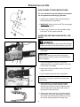
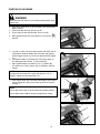
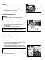
KICK GUARD® TO BAR INSTRUCTIONS
For saws with Kick Guard
®
P/N 2894901 and symmetri-
cal or asymmetrical low-kick type guide bars.
1. Install bolt (A) in rear hole (B) of Kick Guard
®
and
through front hole (C) in guide bar.
2. IMPORTANT: Dimple in Kick Guard
®
(D) must engage
recess in guide bar (E).
3. Tighten nut (F) and bolt (A) until snug. Make certain
Kick Guard
®
is ush against guide bar.
H
G
J
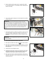
GUIDE BAR AND SAW CHAIN-INSTALL/ RE-
MOVE
WARNING
Saw Chain is sharp! Always wear gloves when handling
assembly, otherwise serious personal injury may result.
1. Move chain brake lever (G) fully rearward to unlock
chain brake.
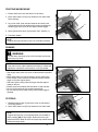
IMPORTANT
Always loosen guide bar nuts before turning chain
tension adjuster, otherwise clutch cover and tensioner
will be damaged.
2. Remove two guide bar nuts (H). Turn tension
adjustment screw (J) counterclockwise 2 to 3 turns if
bar and chain are installed.
3. Push clutch cover (K) forward, pull rear of cover out
slightly, then remove.
4. Remove guide bar and saw chain if necessary.
K
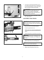
pRepaRation foR use
NOTE: See “MAINTENANCE AND CARE”
instructions for guide bar, sprocket, and saw chain
maintenance.
5. Mount guide bar (L) on studs, and slide toward
sprocket to make saw chain installation easier.
Install saw chain (M) over clutch and place around
sprocket and guide bar as shown, with cutters on
top of guide bar facing forward.
6. Align holes of clutch cover (K) with guide bar studs,
and tensioner pin (N) with lower guide bar adjuster
hole. Install cover, then press and hold rear of cover
to fully seat. Tighten guide bar nuts nger tight.
L
M
N

9
p
o
7. Turn saw over and check brake band (O) for cor-
rect position around clutch drum (P). If brake band
is not in place around drum, remove clutch cover,
make sure brake is released, and reinstall.
DANGER
Never operate saw if chain brake does not
function properly, otherwise saw damage
and serious personal injury could result. See
“Testing the Brake” instructions.
8. Adjust saw chain tension, as instructed in “Adjust-
ment, Chain Tension”
ADJUSTMENT, CHAIN TENSION
IMPORTANT
Always loosen guide bar nuts before turning chain
tension adjuster, otherwise clutch cover and tensioner
will be damaged.
1. Remove air lter cover and spark plug lead.
2. Loosen two guide bar nuts (H).
3. Hold the bar nose up, and turn the adjuster screw
(J) clockwise until the chain touches the bottom of
the bar.
4. Tighten both guide bar nuts with bar nose held up.
IMPORTANT!
Tighten guide bar nuts to 90 – 110 kgf/cm (80 – 95
in. lbs.) DO NOT over-tighten nuts. Damage to saw
may result.
5. Pull the saw chain around the guide bar by hand.
Reduce chain tension, if you feel tight spots.
NOTE
All chains require frequent adjustments.
6. Keep chain properly tensioned at all times.
7. Replace spark plug lead and air lter cover.
HJ

10
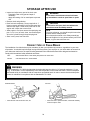
NOTICE: Use of unmixed, improperly mixed, or fuel older than 90 days, (stale fuel), may cause hard starting, poor
performance, or severe engine damage and void the product warranty. Read and follow instructions in the Storage
section of this manual.
fuel stateMent
WARNING
Alternative fuels, such as E-15 (15% ethanol), E-85 (85% ethanol) or any fuels not meeting ECHO requirements
are NOT approved for use in ECHO 2-stroke gasoline engines. Use of alternative fuels may cause performance
problems, loss of power, overheating, fuel vapor lock, and unintended machine operation, including, but not limited
to, improper clutch engagement. Alternative fuels may also cause premature deterioration of fuel lines, gaskets,
carburetors and other engine components.
fuel anD luBRiCant
Gasoline - Use 89 Octane [R+M/2] (mid grade or higher) gasoline known to be good quality. Gasoline may contain
up to 10% Ethanol (grain alcohol) or 15% MTBE (methyl tertiary-butyl ether). Gasoline containing methanol (wood
alcohol) is NOT approved.
Two Stroke Oil - A two-stroke engine oil meeting ISO-L-EGD (ISO/CD 13738) and J.A.S.O.FD Standards must be
used. Echo brand premium Power Blend X
TM
Universal 2-Stroke Oil meets these standards. Engine problems due to
inadequate lubrication caused by failure to use an ISO-L-EGD (ISO/CD 13738) and J.A.S.O.FD certied oil, such as
Echo premium Power Blend X
TM
, will void the two-stroke engine warranty.
IMPORTANT
Echo premium Power Blend X
TM
Universal 2-Stroke Oil may be mixed at 50:1 ratio for application in all Echo en-
gines sold in the past regardless of ratio specied in those manuals.
Handling Fuel
WARNING
Fuel is VERY ammable. Use extreme care when mixing, storing or handling or serious personal injury may result.
• Use an approved fuel container.
• DO NOT smoke near fuel.
• DO NOT allow ames or sparks near fuel.
• Fuel tanks/cans may be under pressure. Always loosen fuel caps slowly allowing pressure to equalize.
• NEVER refuel a unit when the engine is HOT or RUNNING!
• DO NOT ll fuel tanks indoors. ALWAYS ll fuel tanks outdoors over bare ground.
• DO NOT overll fuel tank. Wipe up spills immediately.
• Securely tighten fuel tank cap and close fuel container after refueling.
• Inspect for fuel leakage. If fuel leakage is found, do not start or operate unit until leakage is repaired.
• Move at least 3m (10 ft.) from refueling location before starting the engine.
Mixing Instructions
1. Fill an approved fuel container with half of the required
amount of gasoline.
2. Add the proper amount of 2-stroke oil to gasoline.
3. Close container and shake to mix oil with gasoline.
4. Add remaining gasoline, close fuel container, and remix.
IMPORTANT
Spilled fuel is a leading cause of hydrocarbon emissions.
Some states may require the use of automatic fuel shut-
off containers to reduce fuel spillage.
Fuel Mix Chart
50:1

11
opeRation
IMPORTANT
This saw features a combination ignition/choke switch that automatically sets the throttle speed to fast idle for
quick starting. Do not squeeze trigger during cold starts until after unit has started, or fast idle and choke set-
tings will be released, and engine may not start.
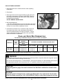
CHAIN LUBRICANT
Proper lubrication of the chain while in operation reduces fric-
tion between the chain and the guide bar to a minimum and
assures a longer service life.
• Use bar and chain oil of high quality for this purpose.
• Do not use used or reclaimed oil to avoid various oiler
problems.
• Use ECHO bar and chain oil.
• When ECHO bar and chain oil is not available:
Use motor oil, etc.
• Use bar and chain oil of the following grades:
SAE NO. 30 ..... in summer
SAE NO. 10 ..... in winter or when cutting resinous trees.
• When refueling, also rell chain oil.
FUEL TANK OIL TANK
TANK INDICATION
WARNING
Moving parts can amputate ngers or cause severe injuries. Keep hands, clothing and loose objects away from
all openings. Always stop engine, disconnect spark plug, and make sure all moving parts have come to a com-
plete stop before removing obstructions, clearing debris, or servicing unit.
After use
• DO NOT store a unit with fuel in its tank. Leaks can
occur. Return unused fuel to an approved fuel storage
container.
Storage - Fuel storage laws vary by locality. Contact
your local government for the laws affecting your area.
As a precaution, store fuel in an approved, airtight con-
tainer. Store in a well-ventilated, unoccupied building,
away from sparks and ames.
IMPORTANT
Stored fuel ages. Do not mix more fuel than you
expect to use in thirty (30) days, ninety (90) days
when a fuel stabilizer is added.
IMPORTANT
Stored two-stroke fuel may separate. ALWAYS
shake fuel container thoroughly before each use.
WARNING
Operation of this equipment may create sparks that can start res. This unit is equipped with a spark arrestor to
prevent discharge of hot particles from the engine. Metal blade use also can create sparks if the blade strikes
rocks, metal, or other hard objects. Contact local re authorities for laws or regulations regarding re prevention
requirements.
Carburetor adjustment
- Idle speed
Carburetor adjustment
- High speed mixture
Wear eyes, ears and head
protection
Carburetor adjustment
- Low speed mixture
Gasoline and oil mixture
Symbol form/shape Symbol description/application Symbol form/shape Symbol description/application
Chain oiler adjustmentChain brake operation
Chain oil pump
Chain oil fill
Emergency stop
Choke control “Cold Start”
position (choke closed)
STOP
INTERNATIONAL SYMBOLS
Read and understand
Operator's Manual.
WARNING
Engine exhaust IS HOT, and contains Carbon Monoxide (CO), a poison gas. Breathing CO can cause uncon-
sciousness, serious injury, or death. Exhaust can cause serious burns. ALWAYS position unit so that exhaust is
directed away from your face and body.

12
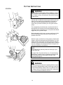
5. Lay unit on a at, clear area and keep bar and chain clear of
all obstacles. Hold top handle with one hand, and depress
throttle trigger lockout (C), but do not depress throttle trigger
(D).
6. Pull starter handle (F) several times until engine starts, or
rst starting sound is heard. (7 pulls maximum)
7. Move ignition/choke lever back to “run” ( I ) position (B).
(Do not move to “Stop” position [G].) If necessary, start the
engine.
NOTE
If engine does not start after 3 pulls with choke in “run” ( I )
position, repeat cold start instructions 4-7.
8. After engine starts, wait 5 seconds then depress and release
throttle trigger (D). Allow unit to warm up at idle for several
minutes.
NOTE
Do not pull starter rope out to the maximum possible position.
Do not allow recoil handle to snap back against the casing.
D
E
C
F
B
C
STARTING COLD ENGINE
WARNING
Make sure bar and chain are not touching anything when start-
ing the saw.
1. Move chain brake lever (E) fully forward to lock chain brake
before starting.
2. Fill the fuel tank with fuel. Do not over ll.
3. Fill the chain oil tank with lubricant. Do not over ll.
4. Move ignition/choke lever (A) forward to “close choke” (
)
position.
A
C
G
E
C

13
A
A
E
D
D
STOPPING
1. Release throttle trigger (D) and move lever (A) rearward to
STOP (O) position.
2. Move chain brake lever (E) fully forward to lock chain brake.
NOTE
If engine does not stop, move ignition/choke lever forward to
choke position ( ) to stop engine. Return the unit to your
authorized ECHO dealer to check and repair stop switch before
starting the engine again.
RUNNING
WARNING
The saw chain should not move at idle, otherwise serious per-
sonal injury may result.
NOTE
If saw chain moves, adjust carburetor according to “Carburetor
Adjustment” instructions in this manual, or see your dealer.
• After engine starts, allow it to return to idle and warm up before
using.
• Move chain brake lever fully rearward to unlock chain brake.
• Press throttle control lockout then gradually squeeze throttle
trigger to increase engine speed.
• Saw chain starts moving when the engine reaches approxi-
mately 4,300 rpm.
• Ensure proper acceleration and lubrication of chain and bar.
• Do not run the engine at high speed unnecessarily.
• Be sure that saw chain stops moving when throttle trigger is
released.
STARTING WARM ENGINE
1. Ensure that there is fuel and chain oil in the tanks.
2. Move chain brake lever (E) fully forward to lock chain brake
before starting.
3. Lay unit on a at, clear area and keep bar and chain clear
of all obstacles.Hold top handle with one hand, and depress
throttle trigger lockout, but do not depress throttle trigger.
4. Move ignition/choke lever (A) forward to “Run” position ( I ).
5. Pull starter handle.
NOTE
If engine does not start after 5 pulls, use cold start procedure.
A
C
E

14
WARNING
Read the ECHO “CHAIN SAW SAFETY MANUAL” included
with your chain saw for additional cutting and safety instruc-
tions. Failure to obey all instructions may result in serious
or fatal injuries.
In all circumstances the operation of the chain saw is a
one-man job. It is difcult at times to take care for your own
safety, so don’t assume the responsibility for a helper as
well. After you have learned the basic techniques of us-
ing the saw, your best aid will be your own good common
sense...
The accepted way to hold the saw is to stand to the left of
the saw with your left hand on the front handlebar and your
right hand on the rear handle so you can operate the throttle
trigger with your right index nger.
Before attempting to fell a tree, cut some small logs or limbs.
Become thoroughly familiar with the controls and the re-
sponses of the saw.
Start the engine, see that it is running properly. Squeeze the
trigger to open the throttle wide open and start the cut. If the
chain is properly sharpened, the cutting should be relatively
effortless. It is not necessary to press down hard to make the
saw cut. Pushing the saw too hard will slow the engine and
cutting will actually be more difcult.
NOTE
Some material may adversely affect the housings of your
ECHO chain saw.
(Example: Palm Tree Acid, fertilizer, etc.) To avoid housing
deterioration, carefully remove all packed saw dust around
clutch and guide bar area and wash with water. Coat
metal parts with light oil.
WARNING
Do not let the tip of the bar touch anything while the engine
is running. At cutting speed the chain is moving at a high rate
of speed. Should the tip contact a limb or log while the chain
is moving, the tip will be pushed upward with considerable
force. This is known as kickback. Avoid it!
CuttinG instRuCtions
Kickback
GENERAL

15
WARNING
A falling tree can seriously damage anything it may hit
- a car, a house, a fence, a power line, or another tree.
There are ways to make a tree fall where you want it,
so rst decide where that is!
Before cutting, clear the area around the tree. You will
need good footing while working and you should be able
to work the saw without hitting any obstacles. Next, select
a path of retreat. When the tree begins to fall you should
retreat away from the direction of fall at a 45 degree angle
and at least 3m from the trunk to avoid the trunk kicking
back over the stump.
Begin the cut on the side to which the tree is to fall. Cut
a notch about 1/3 of the way into the tree as shown. The
position of this notch is important since the tree will try to
fall “into” the notch. The felling cut is made on the side op-
posite the notch and at a level about 2” above the bottom
of the notch. Do not try to cut through to the notch with the
felling cut. The remaining wood between the notch cut and
felling cut (about 2”) will act as a hinge when the tree falls,
guiding it in the desired direction. When the tree starts to
fall, kill the engine, place the saw on the ground and make
your retreat quickly.
To fell big trees with a diameter exceeding twice the bar
length, start the notching cuts from one side and draw the
saw through to the other side of the notch. Start the back
cut on one side of the tree, pivoting the saw through to
form the desired hinge on that side.
Then remove the saw for the second cut. Insert the saw
in the rst cut, very carefully so as not to cause kickback.
The nal cut is made by drawing the saw forward in the
cut to reach the hinge.
Limbing a fallen tree is much the same as bucking. Never
limb on the tree that you are standing. When limbing, cau-
tion is the word. Be careful of the tip touching other limbs.
Always use both hands.
2”
45°
2”
fellinG a tRee
DIRECTION
OF FALL
Direction of fall
Hinge
Felling cut
First cut
Notch
Second cut
One-third tree
diameter
liMBinG

16
Don’t cut with the saw overhead or the bar in a vertical po-
sition. If the saw should kick back you may not have good
enough control to prevent possible injury.
Bucking is the sawing of a log or fallen tree into smaller
pieces. There are a few basic rules which apply to all
bucking operations.
Keep both hands on the handles at all times.
Support logs if possible.
When cutting on a slope or hillside, always stand uphill.
Keep in mind that the wood is heavy and that it will bend
and pinch the saw if improperly supported.
The trunk will weaken at the point where you make the cut
unless the tree is lying on perfectly at ground or supported
as shown.
If you make the cut with the tree on the ground, don’t let the
saw’s chain dig into the earth; it is harmful for the saw, and
you stand a good chance of being struck by ying debris.
To cut the trunk, use the bucking and two-cut sequence
shown. The rst cut should be no deeper than one-third the
trunk diameter.
WARNING
KiCKBaCK is DanGeRous
Kickback is generated when the rotation of the chain is
arrested for some reason. The most dangerous effect
of this action occurs when the nose of the bar contacts
another object, the chain is momentarily stopped and
all the energy of the engine throws the bar upwards and
backwards towards the operator.
The chain saw industry and government agencies have
attempted to prescribe various safety devices, but the
best protection is to avoid kickback.
Comply with the Safety Precautions as listed on page 2
and 3 of this manual.
BuCKinG
Uphill position
FINISH CUT
FIRST CUT
Board or at stones
KiCKBaCK
• Improper thrust cutting.
• When the bar nose hits another tree, etc.

17
MaintenanCe anD CaRe
WARNING
Moving parts can amputate ngers or cause severe injuries. Keep hands, clothing and loose objects away from
all openings. Always stop engine, disconnect spark plug, and make sure all moving parts have come to a com-
plete stop before removing obstructions, clearing debris, or servicing unit. Allow unit to cool before performing
service. Wear gloves to protect hands from sharp edges and hot surfaces.
Your ECHO unit is designed to provide many hours of trouble free service. Regular scheduled maintenance will help
your unit achieve that goal. If you are unsure or are not equipped with the necessary tools, you may want to take your
unit to an ECHO Service Dealer for maintenance. To help you decide whether you want to DO-IT-YOURSELF or
have the ECHO Dealer do it, each maintenance task has been graded. If the task is not listed see your Echo dealer
for repairs.
sKill levels
Level 1 = Easy to do. Common tools may be required.
Level 2 = Moderate difculty. Some specialized tools may be required.
ECHO offers REPOWER
TM
Maintenance Kits and Parts to make your maintenance job easier.
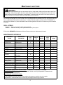
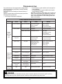
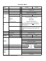
MaintenanCe inteRvals
COMPONENT/
SYSTEM
MAINTENANCE
PROCEDURE
REQ'D
SKILL
LEVEL
DAILY OR
BEFORE
USE
EVERY
REFUEL
3 MONTHS
OR 90
HOURS
YEARLY 600
HOURS
Air Filter Inspect/Clean
1
I / C * R *
Automatic Oiler Inspect/Adjust
1
I
Oil Filter Inspect/Replace
1
I I/C *
Fuel System Inspect/Replace
1
I (1) * I (1) *
Fuel Filter Inspect/Replace
1
I * I / R *
Fuel Cap Gasket Replace
1
I * R
Guide Bar & Sprocket
Nose
Inspect/Clean/Lubricate
1
I / C * I
Saw Chain
Inspect/Sharpen/Replace/
Tensioning
2
I *
Sprocket Inspect/Replace
2
I *
Spark Plug Inspect/Clean
1
I / C / R *
Cooling System Inspect/Clean
2
I / C
Muffler Spark Arrestor Inspect/Clean/Replace
2
I / C / R *
Cylinder Exhaust Port Inspect/Clean/Decarbon
2
I / C
Recoil Starter Rope Inspect/Clean
1
I / C *
Screws/Nuts/Bolts Inspect/Tighten/Replace
1
I *
(1) Low evaporative fuel tanks DO NOT require regular maintenance to maintain emission integrity.
* Replacement is recommended based on the finding of damage or wear during inspection.
MAINTENANCE PROCEDURE LETTER CODES:
I = INSPECT, R = REPLACE, C = CLEAN
IMPORTANT NOTE
- Time intervals shown are maximum. Actual use and your experience will determine the
frequency of required maintenance.
MAINTENANCE PROCEDURE NOTES:

18
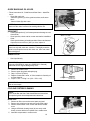
AIR FILTER
1. Close choke (Cold Start Position [ ]). This prevents dirt from
entering the carburetor throat when the air lter is removed.
Brush accumulated dirt from air cleaner area.
2. Remove air lter cover. Brush dirt from inside cover.
3. Remove air lter and lightly brush debris from lter. Replace
lter if it is damaged, fuel soaked, very dirty, or deformed.
4. Install air lter cover.
AUTOMATIC OILER
• The discharge volume of the automatic oiler is adjusted to 6 to 7
cc/min (@ 7000 rpm) prior to shipment from the factory.
• Always check oil discharge when in use.
• Turn adjusting screw (D) counter-clockwise to increase oil volume,
clockwise to decrease oil volume.
OIL STRAINER
• Check periodically.
1. Do not allow dust to enter oil tank.
2. Clogged oil strainer will affect the normal lubricating system
3. Using a wire bent into the shape of a hook, pull strainer out
through oil port and inspect strainer.
4. If the strainer is dirty, clean with suitable cleaning uid.
5. If the inside of the oil tank is dirty, rinse with suitable cleaning
uid.
6. Install strainer into lower front of oil tank to ensure proper
chain lubrication.
FUEL STRAINER
1. Do not allow dust to enter fuel tank.
2. Clogged strainer will cause difculty in starting engine or ab-
normalities in engine performance.
3. Using a wire bent into the shape of a hook, pull strainer out
through gas port, and inspect strainer.
4. If the strainer is dirty, clean with suitable cleaning uid.
5. If the inside of the tank is dirty, rinse with suitable cleaning
uid.
NOTE: Federal EPA regulations require all model year 2012
and later gasoline powered engines produced for sale in the
United States to be equipped with a special low permeation
fuel supply hose between the carburetor and fuel tank. When
servicing model year 2012 and later equipment, only fuel sup-
ply hoses certied by EPA can be used to replace the original
equipment supply hose. Fines up to $37,500 may be enforced
for using an un-certied replacement part.

19
A
B
C
GUIDE BARS AND OIL HOLES
• Follow instructions for “Guide Bar and Saw Chain – Install/Re-
move”.
• Clean after each use
-Clean the grooves (A) of the guide bar with a small screw-
driver.
-Clean oil holes (B) with a wire.
NOTE: Symmetrical shaped Guide Bars should be inverted
each time the chain is removed to extend guide bar life.
SPROCKET
• A damaged sprocket (C) will cause premature damage or wear
of saw chain.
• Clean sprocket, clutch and bar mount area before installation
of bar.
• Check sprocket when you install new chain. When outer diameter
of sprocket is worn 0.5mm (.020”) or more, replace it.
IMPORTANT
Some tree sap and resins are corrosive. Thoroughly wash the
guide bar and sprocket areas after each use, then coat metal
parts with light oil.
Worn : 0.5 mm
C
SPARK PLUG
• Check periodically.
IMPORTANT
Use only NGK BPM-8Y spark plug (BPMR-8Y in Canada)
otherwise severe engine damage may occur.
1. Remove air cleaner cover.
2. Remove spark plug lead and spark plug.
3. Gap = 0.65 mm (0.026 in)
4. Replace if electrode is worn, or if the insulator is fouled by oil
or other deposits
5. Torque = 150 – 170 kgf • cm (130 – 150 in • lbf)
IMPORTANT
Do not over-torque
COOLING SYSTEM CLEANING
NOTE
See “Guide Bar and Saw Chain-Install/Remove Instructions
for sprocket guard removal/replacement instructions.
Mufer Side
1. Remove air lter cover and remove spark plug lead.
2. Remove two guide bar nuts and remove sprocket guard.
3. Remove three mufer cover screws and remove mufer
cover.
4. Using a stiff bristle cleaning brush (do not use a metal
brush), remove debris from cylinder ns in mufer area.
5. Assemble components in reverse order

20
D
Starter Side
1. Remove air lter cover and remove spark plug lead.
2. Remove plastic plug in side handle mount (D), and remove
side handle mounting screw.
3. Remove four starter cover screws and remove starter cover.
4. Using a stiff bristle cleaning brush (do not use a metal
brush), remove debris from ywheel and ignition coil area.
5. Assemble components in reverse order.
MUFFLER SPARK ARRESTOR
IMPORTANT
Carbon deposits in mufer will cause a drop in engine output
and overheating. Spark arrestor screen must be checked
periodically.
1. Remove air lter cover and remove spark plug lead.
2. Remove two guide bar nuts and remove sprocket guard.
3. Remove three mufer cover screws and remove mufer
cover.
4. Remove spark arrestor screen cover, gaskets, and screen
from mufer body.
5. Clean carbon deposits from mufer components.
NOTE
When cleaning carbon deposit, be careful not to damage the
catalytic element inside mufer.
6. Replace screen if it is cracked, plugged, or has holes
burned through.
7. Assemble components in reverse order.
Exhaust Port Cleaning
Level 2.
Parts Required: As needed: Mufer Gasket
1. Remove air lter cover and remove spark plug lead.
2. Loosen chain tension, release chain brake, and remove two guide
bar nuts, clutch cover, guide bar, and chain.
3. Remove mufer cover screws and remove mufer cover. (See
“Guide Bar and Saw Chain – Install/Remove” in Instruction Manual
for detailed disassembly instructions.)
NOTE
Some units may have a metal shim (A) between the mufer cover
and clutch cover. Make sure shim is installed properly when reas-
sembling parts.
4. Place piston at top dead center.
A
Page is loading ...
Page is loading ...
Page is loading ...
Page is loading ...
Page is loading ...
Page is loading ...
Page is loading ...
Page is loading ...
Page is loading ...
Page is loading ...
Page is loading ...
Page is loading ...
-
 1
1
-
 2
2
-
 3
3
-
 4
4
-
 5
5
-
 6
6
-
 7
7
-
 8
8
-
 9
9
-
 10
10
-
 11
11
-
 12
12
-
 13
13
-
 14
14
-
 15
15
-
 16
16
-
 17
17
-
 18
18
-
 19
19
-
 20
20
-
 21
21
-
 22
22
-
 23
23
-
 24
24
-
 25
25
-
 26
26
-
 27
27
-
 28
28
-
 29
29
-
 30
30
-
 31
31
-
 32
32


Ask a question and I''ll find the answer in the document
Finding information in a document is now easier with AI