Page is loading ...

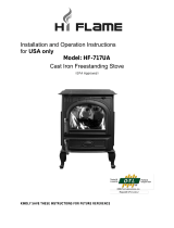
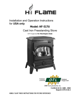
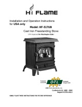
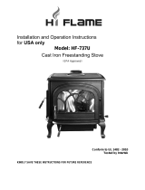
Jøtul F 50 TL Rangeley
Jøtul F 50 TL Rangeley
Wood Stove
Keep these instructions for future reference.
Installation and Operating Instructions
for USA and Canada

2
139262 Rev_H 9 / 11 / 2012
Table of Contents
Accessories ................................................................................... 2
Standards and Safety Notices
Standards / Codes ........................................................................... 3 .....
Safety Notices ..................................................................................4
1.0 Installation
1.1. Assembly Before Installation .............................................. 5
1.2 Flue Collar Installation .......................................................... 6
1.3 Flue Collar Heat Shield .......................................................... 6
1.4 Bottom Heat Shield Installation.........................................6
1.5 Chimney Connector ............................................................... 6
2.0 Chimney Requirements
2.1 Masonry Chimneys ............................................................... 7
2.2 Prefabricated Chimneys ....................................................... 8
2.3 Chimney Height ..................................................................... 8
2.4 Wall Pass-Throughs ...............................................................8
3.0 Connecting to the Chimney
3.1 Masonry Chimneys ............................................................... 9
3.2 Hearthmount into a Masonry Fireplace ........................... 9
3.3 Prefabricated Chimneys ....................................................... 10
3.4 Mobile Home Requirements .............................................. 10
4.0 Clearances to Combustibles
4.1 Floor Protection ...................................................................... 11
4.2 Clearances to Walls and Ceilings ........................................ 11
4.3 Using Shields to Reduce Clearances .................................. 11
4.4 Alcove Installation .................................................................12
4.5 Fireplace Clearances, Mantel and Trim ................................ 12
4.6 Clearance Diagrams .............................................................. 13
5.0 Operation
5.1 Use Solid Wood Fuel Only .................................................... 14
5.2 How your Jøtul F 50 TL works .............................................. 14
5.3 Controling the Fire ................................................................. 14
5.4 Air Control Settings ...............................................................15
5.5 Top Loading Feature ..............................................................15
5.6 Break-in Procedure ................................................................. 15
5.7 Starting and Maintaining a Fire ......................................... 16
5.8 Adding Fuel .............................................................................. 16
5.9 Open Door Fire Viewing ....................................................... 16
5-10 Creosote and the Need for Removal ................................. 17
5.11 Ash Removal ............................................................................ 17
6.0 Maintenance
6.1 Glass Care ................................................................................. 18
6.2 General Care ............................................................................ 18
6.3 Glass Removal or Replacement .......................................... 18
6.4 Gaskets ..................................................................................... 19
6.5 Gasket Replacement ............................................................. 19
6.6 Chimney System .................................................................... 19
7.0 Appendix
7.1 Blower Installation ................................................................ 20
7.2 Outside Air Kit Installation ................................................. 22
7.3 Mobile Home Floor Bracket ................................................ 23
8.0 Illustrated Part List ........................................................... 24
9.0 Warranty Statement .................................................... 26
Jøtul F 50 TL Accessories
Spark Screen #157232
Enjoy the warmth of open door fire-viewing with use of
this custom fit spark screen.
Stove-Top Thermometer #5002
We recommend the use of a magnetic stove-top ther-
mometer to monitor the surface temperature of the
stove.
The optimum surface temperature range for the most
efficient performance is between 400
0
F - 700
0
F
(205
0
C - 316
0
C).
Outside Air Kit #157320
This kit includes a plenum assembly which attaches to
the stove bottom. It permits connection of duct work
from an outside source directly to the air intake of the
stove. A direct outside air connection is required for
mobile home installations.
Mobile Home Floor Bracket Kit #157321
This kit includes two brackets used to fulfill the mobile
home requirement that the stove be secured directly to
the floor.
Blower Kit #156431
This kit includes components for mounting a thermo-
statically controlled 120 cfm blower to the back of the
stove to enhance heat convection into the living area.
Installation and Operation
Instructions for USA/Canada
Installation et
fonctionnement pour Canada
Safety notice: If this solid fuel room heater is not
properly installed, a house fire may result. For your
safety, follow the installation directions. Contact
local building or fire officials about restrictions
and installation inspection requirements in your
area. Save these instructions for future reference.
Avis de sécurité: Une installation non appropriée
de ce poêle de chauffage risque de provoquer
un incendie. Assurez votre sécurité en
respectant les directives d’installation suivantes.
Consultez les autorités locales du bâtiment
ou de la prévention des incendies au sujet
des restrictions et exigences relatives aux
inspections d’installations dans votre région.

3
139262 Rev_H 9 / 11 / 2012
Standards
The Jøtul F 50 TL wood stove has been tested and listed
to: U.S: ANSI/UL 1482 and ANSI/UL 737
Canada: CAN/ULC-S627-M93
Tests performed by:
ITS, Intertek Testing Services
Middleton, WI
Manufactured by:
Jøtul North America
55 Hutcherson Drive
Gorham, Maine 04038-2644
The Jøtul F 50 TL Rangeley wood stove meets the U.S.
Environment Protection Agency’s Emissions limits for
wood heaters manufactured and sold after July 1, 1990.
Under specific, limited laboratory tests, this heater
has shown heat output at rates ranging from 11,700
to 32,900 BTU’s per hour. Actual heat output will vary
depending upon fuel type and quality, home design,
climate, environment, operation, and chimney function.
The Jøtul F 50 TL wood stove is only listed to burn solid
wood only. Do not burn any other fuels.
Read this entire manual before you install and use your
new Jøtul F 50 TL wood stove.
Save these instructions and make them
available to anyone using or servicing the
stove.
Check Building Codes
When installing, operating and maintaining your
Jøtul F 50 TL woodstove, follow the guidelines
presented in these instructions, and make them
available to anyone using or servicing the stove.
Your city, town, county or province may require
a building permit to install a solid fuel burning
appliance.
In the U.S., the National Fire Protection Association’s
Code, NFPA 211, Standards for Chimneys, Fireplaces,
Vents and Solid Fuel Burning Appliances, or similar
regulations, may apply to the installation of a solid
fuel burning appliance in your area.
In Canada, the guideline is established by the CSA
Standard, CAN/CSA-B365-M93, Installation Code for
Solid-Fuel-Burning Appliances and Equipment.
Always consult your local building inspector or
authority having jurisdiction to determine what
regulations apply in your area.
The Jøtul F 50 TL is approved for use in mobile homes.
Install in accordance with 24 CFR, Part 3280 (HUD).

4
139262 Rev_H 9 / 11 / 2012
Installation Tools Required, but not
limited to:
• Measuring Tape
• Phillips screwdriver • Work Gloves
• 10 mm open-end • Safety Glasses
or socket wrench • 4 mm hex key
Safety Notices
• Burnsolidwoodfuelonly
• Donotusechemicalsorfluidstostartthefire.
Donotburngarbageorflammablefluids.
• Readthisentiremanualbeforeyouinstall
and use your new room heater. If this room
heater is not properly installed, a house fire
may result. To reduce the risk of fire, follow
the installation instructions. Failure to follow
these instructions may result in property
damage, bodily injury, or loss of life.
• Contactthelocalbuildingorfireofficials
about restrictions and installation inspection
requirements in your area.
• Donotconnectthisstovetoanyair
distribution duct or system.
• Extremelyhotwhileinoperation!Keep
children, clothing and furniture away. Contact
will cause skin burns. Use a child guard
screen to prevent accidental contact by small
children.
• Installsmokedetectorsinthelivingareasand
bedrooms of your home. Test them regularly
and install new batteries twice annually.
When installed in the same room as the stove,
a smoke detector should be located as far
from the stove as possible to prevent it from
sounding when adding fuel to the fire.
• Avoid creating a low pressure condition in the
room where the stove is operating. Be aware
that operation of an exhaust fan or clothes dryer
can create a low pressure area and consequently
promote flow reversal through the stove and
chimney system, causing potential for carbon
monoxide to enter the living area. The chimney
and building work together as a system -
provision of outside air, directly or indirectly to
an atmospherically vented appliance will not
guaranty proper chimney performance. Consult
your local Jøtul authorized dealer regarding
specific installation/performance issues.
• We recommend that this stove be installed
by a professional solid fuel technician or
that you consult one if you do the work
yourself. Also, consult your insurance
company regarding any other specific
requirements.

5
139262 Rev_H 9 / 11 / 2012
1.0 Installation
If this solid fuel room heater is not properly installed, a
house fire may result. For your safety, follow the installation
directions. Contact the local building or fire officials about
restrictions and installation inspection requirements in your area.
Your local officials have final authority in determining if a
proposed installation is acceptable. Any requirement by the
local authority having jurisdiction that is not specifically
addressed in this manual, defaults to NFPA 211, and local codes
in the U.S. or in Canada, CAN/CSA-B365-M and local codes.
1.1 Unpack the Stove
Inspect the stove for damage. Contact your dealer
immediately if any damage is found. Do not install the stove
if any damage is evident. Contact your dealer.
Contents:
• Top Load Door Tool
• Baffle Handle Assembly
• Bottom Heat Shield
• Flue Collar Heat Shield
• Stove Gloves
• #8 x 12 sheet metal screws, 4 - for Flue Collar Heat Shield
• M6hexnuts,4-forBottomHeatShield
NOTE: The integral Rear Shroud acts as a heat shield.
There is no accessory rear heat shield.
Figure 1. Actuation handles.
Front Door Handle
- ships fully assembled
Baffle Handle Assembly - insert
the shaft into the left side panel.
TopExit
Flue Collar
RearExit
Flue Collar
Top Load Door Tool
6” Ø
(152 mm)

6
139262 Rev_H 9 / 11 / 2012
1.2 Flue Collar Orientation
The Flue Collar is oriented in the Top Exit position. To
change orientation to Rear Exit:
1. Twist and remove the perforated cut-out section from
the top edge of the rear shroud.
2. Use a 10 mm open end wrench or socket wrench to
remove the two M6 x 12 bolts that attach the flue collar
to the stove. Orient the flue collar to the rear and use the
same bolts to re-attach it to the stove.
1.3 Flue Collar Heat Shield
Not applicable for rear exit configuration.
1. Unfold the heat shield as shown in fig.2. Secure it to
the rear stove shroud using the four #8 x 12 sheet metal
screws from the Miscellaneous Hardware Kit.
1.4 Bottom Heat Shield Installation
The bottom heat shield must be installed unless the stove
hearth is composed of poured concrete on earth or unless an
Outside Air Kit is installed.
1. Unfold only the rear panel of the bottom heat shield and
place it under the stove as shown in fig. 3.
2. Unfold the side panels.
3. The heat shield attaches to the four studs protruding
from the stove bottom. Remove the four pre-installed
M6 flange head hex nuts and use them to attach the
shield. See fig. 4.
1.5 Chimney Connector
Use 6” single wall or listed 6” double-wall stovepipe to
connect the stove to the chimney. Single wall stovepipe
must be black steel or stainless steel and have a minimum
thickness of 24 gauge. Do not use aluminum or galvanized
steel pipe for chimney connection - these materials are not
suitable for use with solid fuel.
Follow these guidelines:
• Do not use chimney connector as a chimney. It is intend-
ed only as a connection device.
• Each connector section must be oriented with the male
(crimped) end pointing toward the stove. See fig. 5.
• Secure all connector joints with three sheet metal
screws. The connection to the stove flue collar uses the
two M6x 16 mm self-tapping screws provided.
• For the best performance, the chimney connector should
be as short and direct as possible, including no more
than two 90° elbows.
• The maximum vertical run of single wall stovepipe
should not exceed 10 ft. (305 cm).
Figure 2. Flue Collar
heat shield attachment.
Figure4.Bottomheatshieldattachmentpoints.
Figure 3. Locate the bottom heat shield under the stove
as shown before unfolding the side panels.
Back of Stove

7
139262 Rev_H 9 / 11 / 2012
• Themaximumhorizontalrunshouldnotexceed3ft.
(92 cm) with a 1/4” rise per foot. Under no circumstance
should horizontal pipe be allowed to slant down toward
the chimney.
• No part of the chimney connector may pass through an
attic or roof space, closet or other concealed space, or
through a floor or ceiling. All sections of the chimney
connectors must be accessible for cleaning. Where pas-
sage through a wall or partition of combustible con-
struction is desired, the installation must conform with
NFPA 211 or CAN/CSA-B365, and is also addressed in this
manual.
• Donotconnectthisstovetoachimneyflueserving
another appliance.
2.0 Chimney Requirements
There are two types of approved chimneys:
1. A code-approved masonry chimney with a ceramic tile
or listed steel flue liner.
2. A prefabricated chimney complying with the
requirements for Type HT (2100°F) chimneys per UL 103
or ULC S629.
The chimney size should not be less than the cross-
sectional area of the flue collar, and not more than three
times greater than the cross-sectional area of the flue
collar. If the chimney flue is outdoors, its cross-sectional
area may not exceed two times greater than the stove flue
collar. See also Sect. 3.2.
When selecting a chimney type and the location for the
chimney in the house, keep this in mind: It is the chimney
that makes the stove work - not the stove that makes the
chimney work. This is because a chimney actually creates a
suction, called “draft” which pulls air through the stove.
Several factors affect draft: chimney height, cross-sectional
area (size), and temperature of the chimney, as well as the
proximity of surrounding trees or buildings.
A short exterior masonry chimney will give the poorest
performance because it will be difficult to warm the flue
and sustain the temperatures necessary to maintain draft
strength. In extremely cold climates, it may be necessary to
reline the chimney or extend the height to help establish
draft.
A tall, interior masonry chimney is easier to keep warm
and will perform the best under a variety of weather and
environmental conditions.
The following guidelines give the necessary chimney
requirements based on the national code (ANSI-NFPA
211 for the US. And CSA CAN-B365 for Canada). However,
many local codes differ from the national code to take
into account climate, altitude, or other factors. Your local
building inspector is the final approving authority. Consult
them prior to installation.
Donotconnectthestovetoanyairdistributionductor
system.
2.1 Masonry Chimneys
Follow these guidelines when installing the Jøtul F 50 TL
into a masonry fireplace:
• The masonry chimney must have a fireclay liner or
equivalent, with a minimum thickness of 5/8”
(14 mm) and must be installed with refractory mortar.
There must be at least 1/2” (12.7 mm) air space between
the flue liner and chimney wall.
• The fireclay flue liner must have a nominal size of
8” X 8” (20 cm x 20 cm), and should not be larger than
8”X 12” (20 cm x 30 cm). A round fireclay liner must
have a minimum inside diameter of 6” (15 cm) and
maximum inside diameter of 8” (20 cm).
A larger chimney should be relined with an appropriate
code approved liner.
• Brick or modular block must be a minimum of
4” (10 cm) nominal thickness. Stone construction must
be at least 12” (30 cm) thick.
• A newly-built chimney must conform to local codes,
or, in their absence, must comply with national
regulations.
• An existing chimney must be inspected by a
professional, licensed chimney sweep, fire official, or
code officer to ensure that the chimney is in proper
working order. Any repairs must be completed before
installing the stove.
• No other appliance may be vented into the same flue.
• An airtight clean-out door should be located at the
base of the chimney.
Figure 5.
Chimney connector
orientation.

8
139262 Rev_H 9 / 11 / 2012
Common Method:
See fig. 78 Remove all combustible materials from the pass-
through area ( around the chimney connector), a minimum
12” (30.5 cm). A 6” (15.2 cm) diameter connector will require a
31” x 31” (78.7 x 78.7 cm) square opening.
The opening must be filled with at least 12” (30.5 cm) of
brick around a fireclay liner. The liner must be ASTM C35 or
equivalent, having a minimum wall thickness of 5/8” (16 mm).
The Pass-through must be at least 18” (45.7 cm) from
combustible ceiling materials.
It will be necessary to cut wall studs, install headers, and
construct a sill frame to maintain the proper dimensions
and to support the weight of the brick.
The bricks must be solid brick with a minimum of 3 inches
thick (nominal 4”/ 102 mm).
Figure 7.
Chimney Height
Requirement.
10’
305 cm
2’
61 cm
3’
91.5 cm
2.2 Prefabricated Chimneys
A prefabricated metal chimney must be tested and
listed for use with solid fuel burning appliances. High
Temperature (HT) Chimney Standard UL 103 for the U.S. and
High Temperature Standard ULC S-629 for Canada.
The manufacturer’s installation instructions must be
followed precisely. Always maintain the proper clearance to
combustibles as established by the pipe manufacturer. This
clearance is usually a minimum of 2”, although it may vary
by manufacturer or for certain chimney components.
2.3 Chimney Height
The chimney must be at least 3 feet (92 cm) higher than
the highest point where it passes through the roof and at
least 2 feet (61 cm) higher than the highest part of the roof
or structure that is within 10 feet (3.05 m) of the chimney,
measured horizontally.
Chimneys shorter than 14 feet (4.27 m) may not provide
adequate draft. Inadequate draft can result in smoke
spillage when loading the stove, or when the door is open.
Poor draft can also cause back puffing (ignition of gas
build-up inside the firebox) and sluggish performance.
The minimum height does not, in itself, guarantee proper
chimney performance. Optimum draft force should be in
the .05 - .10 in. w.c. range measured by a Magnahelic gauge.
Draft at .07 w.c. is ideal.
Excessive chimney height can promote over-strong draft
resulting in high stove temperatures and short burn times.
Excessive draft can be corrected by installing a butterfly
damper. Your Jøtul dealer is an expert resource to consult
regarding draft issues or other performance-related
questions.
2.4 Wall Pass-Throughs
Note: In addition to the methods described here, any listed,
prefabricated wall pass-through components available
from chimney manufacurers may be used.
In the U.S.
The National Fire Protection Association’s publication,
NFPA 211, Standard for Chimneys, Fireplaces, Vents and Solid
Fuel Burning Appliances permits four methods for passing
through a combustible wall. Before proceeding with any
method be sure to consult with your local building officials
to discuss any local code requirements.
2” clearance between wall
stud and chimney
Header
Pass-through
construction:
12” brick from
thimble to
chimney
Thimble: 5/8”
Fireclay Liner or
equivalent
Sill/Support
12”
30,5 cm
12”
30,5 cm
Flue Liner
Figure 8.
MasonryWallPass-through.

9
139262 Rev_H 9 / 11 / 2012
3.2 Hearthmount into a Masonry
Fireplace
The Jøtul F 50 TL may be installed into a masonry fireplace
with a minimum opening height of 30 1/2” (77.5 c m).
NOTE: There is no short leg option. DO NOT ALTER OR
REMOVE THE LEGS.
Building code requires that the fireplace damper plate be
removed or securely fixed in the open position.
A connector pipe must then extend from the stove’s flue
exit through the damper area of the fireplace and into the
chimney tile liner. See fig. 10. In any case, we recommend
that a full liner be installed through any masonry chimney
to ensure good performance.
The cross-sectional area of the flue of a chimney with no
walls exposed to the outside below the roofline may be no
more than three times the cross-sectional area of the stove
flue collar.
Figure 10. Hearthmount Installation.
Connector extends at
least into the first flue.
Direct connection to the
chimney cap is highly
recommended.
Damper is sealed
with a steel plate
and high-temper-
ature sealant.
Refractory mortar must be used at the junction of the
chimney and the pass-through liner. The pass-through
liner must not penetrate the chimney liner beyond the
inner surface of the chimney liner. Use extreme care when
constructing the hole in the chimney liner as the tiles can
shatter easily.
In Canada
The installation must conform to CAN/CSA-B365,
Installation Code for Solid Fuel Burning Appliances and
Equipment. Before proceeding be sure to consult your local
building inspector.
Common Method:
This method requires the removal of all combustible
materials from at least 18” (45.7 cm) around the chimney
connector’s proposed location. A 6” round liner requires a
minimum opening 43” x 43” (109.2 x 109.2) square.
Locate the pass-through at least 18” from combustible
ceiling materials.
The space that is cleared of combustible materials must
remain empty. Sheet metal panels can be used to cover
the area. However, when using a panel on both sides of
the wall, each cover must be installed on noncombustible
spacers at least 1” from the wall. If one panel of sheet metal
is to be used it may be installed flush to the wall.
See section 5.3.1 and 5.3.2 of CAN/CSA - B365-M91. Consult
your local building inspector, authorized Jøtul Dealer,
NFPA 211 in the U.S. or CAN/CSA-B635 in Canada for other
approved wall pass-through methods.
3.0 Connecting to the Chimney
3.1 Masonry Chimney
When installing a Jøtul F 50 TL into a masonry chimney
through a “thimble” (the opening through the chimney
wall to the flue), the thimble must consist of ceramic tile or
steel and be securely cemented in place.
The chimney connector/stove pipe must slide completely
inside the thimble to the inner surface or the flue liner. It
may be necessary to make use of a thimble sleeve (a pipe
with a slightly smaller diameter than standard stove pipe).
See fig. 9.
The connector pipe or thimble sleeve must not protrude
into the flue liner or otherwise restrict draft.
Use refractory cement to seal the seam between the
chimney connector, sleeve, and thimble.
Donotconnectthisstovetoachimneyflueservicing
another appliance of any kind.
Figure 9.
MasonryChimneyThimble.
Connector pipe must
be flush with the
inside of the flue tile
Chimney
Connector
Pipe
Thimble
Flue Tile

10
139262 Rev_H 9 / 11 / 2012
The cross-sectional area of the flue of a chimney with one
or more walls exposed to the outside below the roofline
may be no more than two times the cross-sectional area of
the stove flue collar.
If the chimney liner is too large to accommodate the stove,
an approved relining system must be installed to resize the
flue.
A new sheet metal damper block-off plate must be
installed around the connector pipe at the damper frame
and sealed with the proper sealant (usually High-Temp
Silicone).
3.3 Prefabricated Chimneys
When connecting the Jøtul F 50 TL to a prefabricated
metal chimney always follow the pipe manufacturer’s
instructions and be sure to use the all components that are
required. This usually includes a “smoke pipe adapter” that
is secured to the bottom section of the metal chimney and
allows the chimney pipe to be secured to it with two sheet
metal screws. See fig. 11.
3.4 Mobile Home Installation
The Jøtul F 50 TL is approved for installation in
manufactured mobile homes provided the following
requirements are met:
1. All chimney components, including chimney sections,
supports, spark arrestor, etc., shall comply with the Standard
for Factory-built Chimneys for Residential Type and Building
Heating Appliances, UL 103 and/or CAN/ULC-S629 Standard
for 650°C Factory-built Chimneys.
2. The chimney shall be attached directly to the stove and
extend at least 3 ft. (0.9m) above the roof. Termination must
be at least 2 ft. (0.6m) above the hightest elevation of any
part of the mobile home within 10 ft. (3m).
3. In order to allow for transportation of the mobile home,
the chimney termination shall be readily removed at or
below an elevation of 13.5 ft. (4.1 m) above ground level and
reinstalled without use of special tools or instructions.
4. A spark arrester must be installed at the termination. The
net free area of the arrester above the chimney outlet must
not be less than four times the net area of the chimney
outlet, and the vertical height of the arrester must not
be less than one-half the diameter of the chimney flue.
Openings shall not permit the passage of a sphere having
a diameter larger than 1/2” (12.7 mm), and shall permit the
passage of a sphere having a diameter of 3/8” (9.6 mm).
5. Direct connection of the stove to an outside air source is
required. Use Outside Air Kit 157320. Do not substitute any
other connection method or device. See Appendix, Section
7.0. Duct termination must not be installed at a level that is
higher than the air inlet located at the bottom of the stove.
6. The stove must be secured to the mobile home floor. Use
Floor Bracket Kit 157321.
7. When the chimney exits the mobile home at a location
other than through the roof, and exits at a point 7 ft. (2.1 m)
or less above the ground level, a guard or other method of
enclosing the chimney, must be provided at the point of
exit for a height up to 7 ft. Openings of this chimney guard
shall not permit penetration of a 3/4 in. (19.1 mm) diameter
rod, or contact with the chimney by a 1/2 inch (12.7 mm)
diameter rod inserted through the opening a distance of
4 inches (102 mm).
8. Provision must be made for electrical grounding of the
chimney, chimney connector, and stove in accordance with
local building codes.
WARNING:Donotinstallthisapplianceinasleepingroom.
CAUTION: The structural integrity of the mobile home floor,
walls, and ceiling/roof must be maintained.
Listed Chimney
Specified
clearance
Attic
Insulation
Shield
Chimney
Connector
Figure11.PrefabricatedListedTypeHTChimney.
Combustible
Ceiling Joists
Storm Collar
Listed Cap
Combustible
Ceiling Joists
Flashing
Chimney
Connector
Ceiling
Support
Chimney
Adaptor

11
139262 Rev_H 9 / 11 / 2012
4.1 Floor Protection
The Jøtul F 50 TL includes a bottom heat shield which must
be installed unless the stove is on a concrete floor poured
on earth.
The Jøtul F 50 TL requires one of the following forms of
hearth protection if not installed directly on concrete
poured on earth:
1) Any UL, ULC, or Warnock Hersey Listed Type 1 hearth board.
2) Any noncombustible material.
In the U.S. floor protection must extend forward from the
door opening at least 16 in. and 8 in. from the sides of the
door opening. Protection must also extend 2 in. under the
chimney connector. This will result in a minimum floor
protector 33” wide x 40 3/4” deep. See fig 12.
In Canada, floor protection must extend 18” from the
front of the stove and 8 in. (460mm) from the sides and
rear. It must also extend 2 in. (51 mm) under the chimney
connector. This results in a floor protector 43 1/2 in. x 50 1/2
in. (110.5 cm. x 128.2 cm.) See fig.12-a.
4.2 Clearances to Walls and Ceilings
The clearances listed and diagramed in this manual have
been tested to UL and ULC standards and are the minimum
clearances to combustible materials specifically established
for the Jøtul F 50 TL.
A combustible surface is anything that can burn (i.e. sheet
rock, wall paper, wood, fabrics etc.). These surfaces are not
limited to those that are visible and also include materials
that are behind noncombustible materials.
If you are not sure of the combustible nature of a material,
consult your local fire officials.
Remember: “Fire Resistant” materials are considered
combustible; they are difficult to ignite, but will burn. Also
“Fire-rated” sheet rock is also considered combustible.
Contact your local building officials about restrictions and
installation requirements in your area.
See pages 12-13 for clearance requirements and diagrams.
4.3 Using Shields to Reduce Clearances
Double Wall Connector: Listed double wall pipe is an
acceptable alternative to connector pipe heat shields.
Wall-Mounted Protection: When reducing clearances
through the use of wall-mounted protection:
In the U.S. refer to NFPA 211, Standard for Chimneys, Fireplac-
es, Vents and Solid Fuel Burning Appliances, for acceptable
materials, proper sizing and construction guidelines.
In Canada, refer to CAN/CSA-B365, Installation Code for
Solid-Fuel Burning Appliances and Equipment, also for
acceptable materials, proper sizing and construction
guidelines.
Notice: Many manufacturers have developed woodstove
accessories that permit clearance reduction. Use only
those accessories that have been tested by an independent
laboratory and carry the laboratory’s testing mark. Be sure
to follow all of the manufacturer’s instructions.
4.0 Clearance to Combustibles
Figure12-a.FloorProtectionminimumdimensions,Canada.
Figure 12. Floor Protection minimum dimensions, U.S.

12
139262 Rev_H 9 / 11 / 2012
4.5 Clearances to Fireplace Mantels
and Surrounding Trim
See the Clearance Chart on page 13 for approved clearances
to combustible materials that may be part of fireplace
construction.
Mantel and Trim clearances may be reduced by 50% with
use of shielding constructed in accordance with NFPA 211
specifications.
Figure13.AlcovewithUnprotectedWalls.
Figure14.AlcovewithWallProtection.
Figure 15. Hearthmount Clearances.
4.4 Alcove Installation
The Jøtul F 50 TL can be installed in an alcove as
diagrammed in figs. 13.-14.
1. The stove must be installed only with double-wall chim-
ney connector.
2. Wall and ceiling protection, if used, must extend over the
entire area.
3. Alcove floor protection must consist of a UL/ULC or WHI
listed hearth pad or a non combustible material.
4. Minimum Alcove Ceiling Height:
Unprotected Surface - 72” (183 cm)
Protected Surface - 59” (150 cm)

13
139262 Rev_H 9 / 11 / 2012
4.6 Jøtul F 50 TL Clearance Specifications
UNPROTECTEDWALLS
PROTECTEDWALLS
PERNFPA211ORCAN/CSA-B365-M93
SIDE REAR CORNER SIDE REAR CORNER
Single Wall Connector
A
14” / 356 mm
B
18” / 457 mm
C
12” / 305 mm
D
12” / 305 mm
E
8” / 203 mm
F
8.5” / 216 mm
Single Wall Connector
w/ Flue Collar Heat Shield
G
16” / 406 mm
H
10” / 254 mm
I
11” / 280 mm
J
8” / 203 mm
K
5” / 127 mm
L
6” / 153 mm
DoubleWallConnector
M
14” / 356 mm
N
9” / 229 mm
O
12” / 305 mm
P
6” / 152 mm
Q
8” / 203 mm
R
6” / 152 mm
DoubleWallConnector
w/ Flue Collar Heat Shield
S
14” / 356 mm
T
6” / 152 mm
U
12” / 305 mm
V
5” / 127 mm
W
6” / 152 mm
X
3.5” / 89 mm
Alcovew/Double-Wall
Connector
A
16” / 406 mm
B
19” / 483 mm
N/A
D
6” / 152 mm
E
8” / 203 mm
N/A
Figure16.ClearanceDiagrams.Allspecificationsapplicabletobothtopandrearexitconfigurations.

14
139262 Rev_H 9 / 11 / 2012
5.0 Operation
Please read the following section before building the first
fire in your new Jøtul F 50 TL.
5.1 Use Solid Wood Fuel Only
This stove is designed to burn natural wood only. Wood
that has been air-dried for a period of 6 to 14 months will
provide the cleanest, most efficient heat.
Donotburn:
• Coal • Treated or painted wood
• Garbage • Chemical Chimney cleaners
• Cardboard • Colored paper
• Solvents • Any synthetic fuel or logs
• Drift wood • Laminated wood
The burning of any of these materials can result in the
release of toxic fumes. Never use gasoline, gasoline-type
lantern fuel, kerosene, charcoal lighter fluid, or similar
liquids to start or “freshen-up” the fire. Always keep such
liquids away from the heater at all times.
Important: Never build or allow the fire to rest directly on
the glass panel. Try to keep the logs spaced at least one
inch from the glass to allow for proper air flow over the
glass and within the firebox.
5.2 How your Jøtul F 50 TL works
When used with dry wood and a well-drafting chimney
system, modern non-catalytic wood stoves burn fuel
efficiently by the precise control and delivery of primary
and secondary air to the fire.
Primary Air is drawn into a front inlet in the stove bottom
and directed through a regulator shutter under the front
door before entering the lower fire chamber. Additional
primary air is directed to the top of the front door to act
as an air wash which may prevent extreme soot build-up
on the glass panel. The amount of primary air available to
the fire determines the intensity of heat output and rate of
fuel combustion; the greater the amount of air, the greater
the heat output, the faster the wood burns. The primary
air setting also determines the effectiveness of the air wash
over the glass; the higher the setting, the cleaner the glass.
Additional air is separately directed into the top of the fire
chamber to support combustion of exhaust gasses before
passing out of the stove. This unregulated Secondary Air
enters through an inlet in the rear of the stove bottom
and is heated as it passes through the rear of the stove
into a two-tiered manifold at the top of the firechamber.
Additional secondary air is directed through a stainless
steel tube built into the baffle plate hinge. Volatile gases,
WARNING
ALWAYSWEARSTOVEGLOVESWHILETENDINGTHEFIRE.
NEVERALLOWTHEFIRETORESTDIRECTLYONTHE
GLASS.KEEPTHELOGSSPACEDATLEASTONEINCHFROM
THEGLASSTOALLOWFORPROPERAIRFLOWWITHINTHE
STOVE.AVOIDSTRIKINGTHEGLASSWITHLOGS.
OPERATETHISSTOVEONLYWITHTHEFRONTDOOR
ANDASHDOORFULLYCLOSED.OPERATIONWITHTHE
DOORPARTIALLYOPENMAYRESULTINOVER-FIRING.
IFTHEDOORISLEFTPARTIALYOPEN,GASANDFLAME
MAYBEDRAWNOUTOFTHESTOVECREATINGSAFETY
RISKSFROMBOTHFIREANDSMOKE.
Figure 16.
Combustion air paths
Volatile gases, released unburned from the fuel bed, rise to
the baffle where they are turbulently mixed with the hot,
fresh oxygen. Secondary combustion then occurs before the
gases pass into the heat exchange chamber. See fig. 16.
5.3 Controlling the Fire
Combustion intensity is controlled by the position of an
air shutter located under the front door. You adjust its
position using the handle located under the ash lip. Slide
the handle to the left to decrease air to the fire. Sliding it
to the right increases air delivery and consequently, fire
intensity. See fig. 17. The shutter regulates and directs
primary air to the front of the burn chamber. Push it to
the right to allow maximum air to support combustion. It
should be fully open when first starting or rekindling a fire,
or when greater heat output is desired.

15
139262 Rev_H 9 / 11 / 2012
5.5 Top Loading
You will want to take advantage of the convenience of
adding logs to a burning fire through the top of your stove.
The hinged heat exchanger baffle must be in the open
position in order to add wood to the fire through the top
of the stove. The baffle handle can be set in any of four
positions, however, we recommend that you orient it to
mimic the orientation of the baffle itself.; i.e. when the
side handle is in a horizontal position, the baffle is also in a
horizontal position - Closed. Swing the handle down into a
vertical position to open the baffle. See fig. 18 and section
5.7 for more details.
WARNING:
NEVEROVER-FIRETHESTOVE.IFANYPARTOFTHE
STOVEORCHIMNEYGLOWS,YOUAREOVER-FIRING.
AHOUSEFIREORSERIOUSDAMAGETOTHESTOVE
ORCHIMNEYCOULDRESULT.IFTHISCONDITION
OCCURS,IMMEDIATELYCLOSETHEAIRCONTROL.
Use the following guide for best performance.
Burn Rate Air Control Setting Blower Speed
Min. Low Min. Open Low / On at 30 min.
Med. Low 3/8” Open Low / On at 30 min.
Med. High 3/4” Open Low / On at 30 min.
High Max. Open High / On
5.4 Air Control / Blower Settings
Figure 17. Air Control Settings
5.6 Break-In Procedure
Although your Jøtul F 50 TL is constructed of welded, 1/4”
steel plate, it also incorporates cast iron components. This
material requires the stove to be“broken-in” gradually so
that heat expansion does not occur too quickly and cause
damage. The following steps describe the proper break-
in procedure for your stove. Use a magnetic stove-top
thermometer to monitor stove temperature, placed directly
on the cook plate.
Set the Primary Air Shutter fully open, all the way to the right.
1. Light a small fire of newspaper and kindling at the
front of the stove. Gradually add small pieces of wood,
but only allow the stove to reach a maximum surface
temperature of 200°F (93° C). Continue burning at this
low rate for approximately 1 hour.
2. Allow the stove to cool to room temperature.
3. Light a second fire, allowing the stove to reach a
maximum temperature of 300°F (149°C) for 1 hour.
4. Cool the stove to room temperature.
5. Light a third fire and gradually allow the stove to reach a
surface temperature of 400°F (204°C)
6. Cool the stove to room temperature. This completes the
“break-in” procedure.
Note: If the temperature exceeds the limit during any
break-in fire, move the Air Shutter all the way to the left
to shut off the air supply completely. It is normal that the
stovetop temperature will continue to climb until the fuel
burns down somewhat. Once the fire is out and the stove
has cooled to room temperature, continue the break-in
procedure. Never attempt to reduce the temperature by
removing burning logs from the fire.
Figure 18. Baffle handle orientation.
Break-in Odors: It is normal for a newly-painted
stove to emit odor and smoke during the first
few fires, and these may set off smoke alarms.
This condition is caused by curing of the high
temperature paint and will diminish with each
subsequent fire. It is advisable to open windows
or doors to provide plenty of fresh air and cross-
ventilation during the break-in period.
CLOSED
OPEN

16
139262 Rev_H 9 / 11 / 2012
5.8 Adding Fuel
Follow this procedure when reloading the stove while it is
still hot and a bed of hot embers remains:
• Always wear gloves when tending to the stove.
• Adjust the Primary Air Shutter Lever to the fully open
position and open the baffle plate. Wait a few seconds to
re-establish strong draft before opening the load door. This
will allow fresh air to flush the firebox and prevent smoke
escaping when either the front or top door is opened.
• Open the Baffle and Top Door,
Or,
Open the Front Door.
DO NOT LOAD THROUGH THE TOP WHEN THE FRONT
DOOR IS OPEN.
• Use a stove tool or poker to evenly distribute coals and
embers around the firebox.
• Load the fuel, usually with smaller logs first.
• Close the Front Door, being sure to latch the door tightly.
Or,
Close the Baffle and then the Top Load Door.
• Wait 5 – 10 minutes before setting the air controls for
the desired heat output and burn time.
(If you have at least a 2” thick ember bed when
reloading, it may be possible to close the door and
immediately adjust the air control setting).
• Set the Air Shutter on the door for the desired heat
output.
5.9 Open Door Fire-viewing
Warning: This stove should be operated with the door
either fully open with optional Spark Screen in place or
with the door fully closed. If the door is left partly open,
there is risk of overfiring. Also, gas and flame may be drawn
out of the fireplace stove opening, creating risks from both
fire and smoke.
Be aware that, when operating with the door open, there
exists the possibility of carbon monoxide generation by
charcoal, Good draft is essential to minimize the potential
for CO to be introduced into the living space. Be sure
adequate fresh air and ventilation are available to the stove
when using the spark screen.
5.7 Starting and Maintaining a Fire
Burn only solid wood directly on the bottom grate of the
stove. Do not elevate the fire in any way.
WARNING:DONOTOPERATETHISSTOVEWITHTHEASH
DOOROPEN.DOINGSOMAYCAUSEDAMAGEANDWILL
VOIDYOURWARRANTY.
We recommend use of a magnetic stovetop thermometer
to monitor the surface temperature of the stove. Locate
the thermometer directly on one of the rear corners of
the Griddle/Load Door. The optimum surface temperature
range for most efficient combustion is between 400° and
700° (204°C -371°C). Chimney draft should be in the
.05 - 1.0 w.c. range.
1. With the Primary Air Shutter in the full open position
(to the right), start with several sheets of crumpled
newspaper placed directly on the grate. On top of the
newspaper, place several pieces of small dry kindling *
(1” - 2” in diameter or less) with two to three larger logs
(approx. 3” to 4” in diameter) on top.
2. Light the fire and close the door. Allow the chimney to
warm and establish a strong draft. Use your stove glove
and slowly build the fire by adding larger and larger
logs. Be sure to follow the break-in procedure (Sect. 5.6)
before creating a hot fire that might damage the stove.
3. Once the stove has reached a surface temperature range
of between 400° and 700°, (204°C -371°C), adjust the
primary air control lever as appropriate to generate the
desired heat output and burn time.
With time and experience, you will soon become
acquainted with the operating characteristics of your
particular installation.
You can also monitor stove performance through the
window. Peak combustion efficiency occurs when exhaust
gas is burned at the baffle in the top of the firebox. This is
apparent as rolling yellow-orange flames appearing at the
secondary air ports in the underside of the baffle plate and
forward tube. At this stage, little or no smoke will be visible
exiting the chimney.

17
139262 Rev_H 9 / 11 / 2012
5.10 Creosote Formation and the
Need for Removal
When wood is burned slowly, it produces tar and other
vapors that combine with moisture to form creosote.
Creosote vapors condense in the relatively cool chimney
flue, and creosote residue accumulates on the flue
lining. When ignited, this creosote fuels an extremely
hot fire.
The chimney connector and chimney flue should be
inspected at least twice monthly during the heating
season to determine if creosote buildup has occurred.
If creosote has accumulated, it should be removed to
reduce the chance of a chimney fire.
In the event that creosote ignites in the flue, the
resulting fire is often accompanied by a roaring noise
and crackling sound as flakes of burning creosote break
loose. If you suspect you are having a chimney fire,
immediately close the air controls and make sure the
door is closed securely. Call the fire department and have
everyone leave the house.
Do not attempt to extinguish the fire. Opening the door
will only supply additional oxygen and intensify the
fire. When the fire in the flue has subsided, resist the
temptation to open the door to check on the fire. The fire
may have suffocated, but could re-ignite with a supply of
fresh air. After a chimney fire, do not use the stove until
the chimney connector and flue have been cleaned and
inspected to ensure no damage has been sustained.
See Section 6.6 of this manual regarding chimney
cleaning.
5.11 Ash Removal
Ashes will drop through the bottom grate into the inter-
nal ash pan during normal operation. Empty the ash pan
periodically, depending on how frequently the stove is used.
Avoid letting the ash accumulation to spill over the pan and
into the pan housing.
Always wear safety gloves when handling the ashes.
Ashes should only be placed in a metal container equipped
with a tight sealing lid. The container should be placed on
a noncombustible floor or on the ground, well away from
all combustible materials, pending final disposal. If the
ashes are disposed of by burial in soil or otherwise locally
dispersed, they should be kept in the closed container until
all cinders have thoroughly cooled.

18
139262 Rev_H 9 / 11 / 2012
Important: Replace glass only with ceramic glass panel
PN 224158 specifically designed for the Jøtul F 50 TL
Do not use substitutes. Replacement glass is available
from your local Jøtul dealer.
6.2 Glass Care
Cleaning
On occasion it will be necessary to clean the carbon deposits
and fly ash off of the glass. If these deposits are allowed
to remain on the glass for an extended period of time, the
surface may become etched and cloudy. Any creosote that
might develop on the glass will burn off during the next hot
fire.
Follow this glass cleaning procedure:
1. Glass must be completely cool.
2. Only use a cleaner that is specifically designed for this
purpose. The use of abrasives will damage the glass and
ultimately leave the glass frosted.
3. Rinse and dry glass completely before burning the stove.
Polish with a piece of newspaper.
Caution! Always operate the door slowly and carefully to
avoid cracking or breaking the glass. Never use the door to
push wood into the firebox. If the glass becomes cracked or
broken follow the replacement procedure below.
Never operate the stove with a cracked or broken glass
panel.
6.0 Maintenance
6.1 Door Latch Adjustment
Over time, as the door gasket becomes compressed, it may
be necessary to adjust the door latch in order to maintain
the integrity of the door seal. To check the seal of the front
door, close and latch the door on a dollar bill and slowly try
to pull the bill free. You should feel resistance as you pull.
If it can be easily removed, the seal is too loose. Follow this
procedure to tighten the latch mechanism.
Tools Required:
• 4 mm hex key
1. Remove the two socket head screws and latch keeper
from the stove. See fig. 19.
2. Remove one of the shim plates from the latch cavity
and re-install the latch keeper. Retain the shim plate(s)
removed for future use.
3. Test the seal integrity using the dollar bill.
The door gasket will compress over time. When the latch
can no longer be tightend by shim removal, install a new
gasket and replace the shim plates.
Figure 19. Latch adjustment.
Shim Plates
Latch Keeper

19
139262 Rev_H 9 / 11 / 2012
Figure 20. Glass and Gasket Replacement
Description PartNumber
1. Door Gasket 223858
2. Glass Gasket 200024
3. Gasket Clamp 224257
4. Screw, M6x10 Button Hd. 117978
5. Lower Glass Clip Asy, 157357
6. Glass Panel 224158
7. Upper Glass Clip Asy. 157352
6.3 General Care
As with your car, regular maintenance will assure good
performance and prolong the life of your stove. The
following procedures do not take long and are generally
inexpensive. When done consistently, they will increase the
life of your stove and in turn,provide years of enjoyment.
• Regularly empty the stove of all soot and ashes. Only
use a vacuum for this job if the vacuum is specifically
designed to handle ashes. CAUTION: Ashes can contain
live embers. Be certain the ash bed contains no live
embers before using a vacuum.
• Inspect the stove: Using a strong light inspect the stove
inside and out for cracks or leaks.
• Replace any broken bricks. See fig. 29, page 24. DO NOT
OPERATE THE STOVE WITH BROKEN OR MISSING BRICKS.
6.4 Gasket Replacement
1. Use pliers and a putty knife to remove the old gasket and
adhesive from the door.
2. Thoroughly clean the channel with a wire brush.
3. Apply a small bead of cement to the channel.
4. Gently press the new gasket into the cement to seat it in
the channel. Wrap the two ends around and secure with
the gasket clamp as shown in fig. 20. Close and latch the
door and then reopen. Wipe away any excess cement
that may have squeezed out from around the gasket.
6.5 Glass Removal or Replacement
See fig. 20.
1. Place the door face down on a protected surface.
2. First just loosen each glass clip screw and then remove
the clips.
3. Lift the glass panel out of the door. Use pliers and a
putty knife to remove the old glass gasket. Replace with
PN 200024, .025 dia. LD2 gasket. Apply a small bead of
cement in the channel and gently press the gasket into
place.
4. Replace the glass and glass clips. Tighten the clips
gradually, avoiding placing uneven pressure on the glass.
6.6 Chimney System
The Jøtul F 50 TL is designed to burn cleanly and efficiently
when used according to the guidelines in this manual. In
order to maintain proper performance, you should inspect
the chimney and chimney connector at the beginning of
each heating season and then every eight weeks during
the heating season. Clean the chimney whenever creosote
and fly ash accumulation exceeds 1/4 inch in any part of the
system. If the stove. Also, use a shop vacuum to remove any
debris that may have accumulated on the stove baffle.
Chimney brushes are available from your local Jøtul dealer
or hardware supply store. Your dealer can also refer you to a
reputable, professional chimney sweep who will have all the
equipment to ensure a complete and proper job.
WARNING:FAILURETOKEEPTHECHIMNEYCONNECTOR
ANDFLUEFREEOFCREOSOTEBUILD-UPCANRESULTINA
CHIMNEYFIRE.

20
139262 Rev_H 9 / 11 / 2012
7.0 Appendix
7.1 Optional Blower 156431
Installation
Install the blower kit before moving the stove into its final
position. If the stove is already installed, you may need to
pull it out to install this blower.
For Freestanding stove installations, where access to
the back of the stove is unrestricted, the Control Box may be
mounted to either corner of the rear shroud.
For Alcove or Hearthmount installations into fireplaces,
the Switch Box must be mounted under the stove, attached
to the side of the bottom heat shield. Determine the loca-
tion most appropriate to your needs and follow the installa-
tion steps outlined below.
1. Remove the Rear Shroud:
Use the 4 mm hex key to remove the socket head screws and
nuts at the bottom of each side of the Rear Shroud.
See fig. 22, A.
Loosen the two hex nuts at the upper rear of the stove and lift
the shroud up off of the stove. See fig. 22, B. Keep all shroud
fasteners for reassembly.
CAUTION:
Avoid injury- always wear work gloves when handling sheet
metal parts. Read through these instructions to familiarize
yourself with these parts before beginning the installation.
115VAC,60HTZ,Max.40Watts
This blower must be electrically grounded in
accordance with local codes or, in the absence
of local codes, with the current ANSI/NFPA 70,
NationalElectricalCodeorCSAC22.1-Canadian
ElectricalCode.
This unit is supplied with a three-prong
(grounding) plug for protection against shock
hazard and should be plugged directly into
a properly grounded three-prong receptacle.
DONOTCUTORREMOVETHEGROUNDING
PRONGFROMTHEPLUG.
Donotconnecttopowersupplyuntilall
electical connections have been made.
Always disconnect the power supply when
performing any service.
Tools Required
• 10 mm wrench or socket driver
• pliers
• 1/4” socket driver or flat head screwdriver
• 4 mm hex key • work gloves
2. AttachtheAirDeflector:Seefigs.21and22/#3.
Use pliers to bend the deflector tabs at the perforation lines as
shown. Attach the deflector to the interior side of the rear shroud
using two #8 X 12 sheet metal screws from the exterior side.
3. Attach the Blower Mounting
Bracket.
Use pliers to bend back the
long, vertical flange to allow
the bracket to fit flush against
the back of the stove. (Fig. 22
and 23 /#2) to the two center
studs on the back of the stove,
oriented as shown. Secure
with two M6 flange nuts.
4. Attach the Blower to the
Mounting Bracket using the
two wing nuts (Fig. 23 /#9).
5. Attach the Snapstat Bracket to
the lower stud on the back of
the stove, oriented as shown
in fig. 23 /#7.
Slide the small Snapstat (#6,
marked F110-20) all the way
into the bracket slot between
the stove and the bracket.
Connect either snapstat lead
to either snapstat terminal.
6. Install the Control Box, fig. 23 /#4:
The control box may be mounted to the side of the stove closest
to the nearest electrical outlet.
Freestanding Installation-
Attach the control box to either side of the rear shroud using a 1/4”
socket driver and one #8 x 12 sheet metal screw as shown in fig. 23.
Alcove or Hearthmount Installation -
Attach the Control Box Mounting Bracket (#5) to the back of
the Control Box using two #8 x 12 sheet metal screws.
Attach the Mounting Bracket/Control Box assembly to the side
of the Bottom Heat Shield using four #8 x 12 sheet metal screws.
7. BendbacktheLowerAirDeflectorpanelontherearshroud.
Reinstall the shroud by reversing the procedure in Step 1.
Engagetheshroudwiththeupperhexnutsonthebackofthe
stove and then reinstall the socket head screws at the bottom
of each side.
Blower
Mounting
Bracket
BEND
Figure 21. Air Deflector orientation.
Air Deflector
BEND
BEND
BEND
BEND
Figure 22. Blower Bracket
adjustments.
/