System Sensor 2112/24R and 2112/24TR User manual
- Category
- Smoke detectors
- Type
- User manual
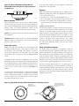
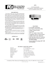
System Sensor 2112/24R and 2112/24TR are advanced photoelectronic smoke detectors designed to provide reliable fire detection in residential and commercial applications. With a sleek design and a range of features, these detectors offer enhanced protection and ease of use. The 2112/24R model operates on 12 or 24 VDC and is ideal for smoke detection, while the 2112/24TR model additionally includes a 135°F fixed-temperature heat sensor for added protection.
System Sensor 2112/24R and 2112/24TR are advanced photoelectronic smoke detectors designed to provide reliable fire detection in residential and commercial applications. With a sleek design and a range of features, these detectors offer enhanced protection and ease of use. The 2112/24R model operates on 12 or 24 VDC and is ideal for smoke detection, while the 2112/24TR model additionally includes a 135°F fixed-temperature heat sensor for added protection.


-
 1
1
-
 2
2
-
 3
3
-
 4
4


System Sensor 2112/24R and 2112/24TR User manual
- Category
- Smoke detectors
- Type
- User manual
System Sensor 2112/24R and 2112/24TR are advanced photoelectronic smoke detectors designed to provide reliable fire detection in residential and commercial applications. With a sleek design and a range of features, these detectors offer enhanced protection and ease of use. The 2112/24R model operates on 12 or 24 VDC and is ideal for smoke detection, while the 2112/24TR model additionally includes a 135°F fixed-temperature heat sensor for added protection.
Ask a question and I''ll find the answer in the document
Finding information in a document is now easier with AI
Related papers
-
System Sensor 2112/24ATR User manual
-
-
-
-
-
-
System Sensor 2151 User manual
-
-
-
Other documents
-
ADEMCO 5808LSTA Installation guide
-
Honeywell 5193SD Installation And Maintenance Instructions
-
Yamaha 02R Version 2 Owner's manual
-
-
-
 FCI Home Appliances 2151 User manual
-
Home Automation 20A00-1 User manual
-
Altronix AL802ULADAJ Installation guide
-
-
Radionics D285 Installation guide
