Page is loading ...

MODEL 3121 3122 3123
Model-31213122 Model-3123
HIGH VOLTAGE INSULATION TESTER
OPERATING INSTRUCTIONS
7/05 FORM#341

CONTENTS
Page
1Features 1
2Specifications 2 3
3Instrument Layout 4
4Operating Instructions 5
4-1Mechanical Zero Adjustment 5
4-2Battery Check 5
4-3Insulation Resistance Measurement 6
4-4Continuous Measurement 6
4-5Use of Guard Terminal 7
5Battery Replacement 8
6Cleaning Meter Cover 8

1
1. Features
Battery powered, the instruments test insulation up to
100000M at 2500V for Model 3121, 200000M at 5000V
for Model 3122 and 200G at 5000V and 400G at 10000V
for Model 3123.
Suited for heavy duty electrical maintenance and servicing of
industrial installations, cables, transformers, generators and
switchgear where high voltage insulation tests are required.
Dual scales for low and high ranges which change
automatically. Colour coded scales for easy reading plus
LED's that illuminate in matching colour.
Drip proof construction. The case is sealed with rubber
gaskets to protect internal circuit against rain.
Hard carrying case furnished as standard accessory. Houses
both instrument and test leads in compact form. Made of
plastic, it is highly water resistant.
Designed for low power consumption. Since the maximum
current consumption is 90mA eight pieces of 1.5V SUM-3or
equivalent permit about 6 hours of continuous operation
even when the instrument is used on maximum load or twice
longer on minimum load.
Rated output voltage is maintained down to 100M for Model
3121,200M for Model 3122 and 0.2G/0.4G for Model
3123. This permits accurate measurements of low insulation
resistance.

2
Model 3121 Model 3122 Model 3123
DC Test Voltage 2500V 5000 V 5000V10000V
Measuring Ranges
02000M/
1000100000M
automatic change
05000 M/
2000 200000M
(automatic change)
05G/2200G
(automatic change)
010G/4400G
(automatic change)
Accuracy Insulation
Resistance
5% of reading
10050000M
10% of reading
or 0.5% of scale length
ranges other than
listed above
at 23 5
10% of reading
10050000M
20% of reading
or 1.0% of scale length
ranges other than
listed above
at 1040
5% of reading
200 100000M
10% of reading
or 0.5% of scale length
ranges other than
listed above
at 23 5
10% of reading
200 100000M
20% of reading
or 1.0% of scale length
ranges other than
listed above
at 10 40
5% of reading
0.2100G
10% of reading
or 0.5% of scale length
ranges other than
listed above
at 23 5
10% of reading
0.2100G
20% of reading
or 1.0% of scale length
ranges other than
listed above
at 1040
5% of reading
0.4200G
10% of reading
or 0.5% of scale length
ranges other than
listed above
at 23 5
10% of reading
0.4200G
20% of reading
or 1.0% of scale length
ranges other than
listed above
at 1040
Output
Voltage
2500V 5%
10050000M
5000V 5
200 100000M
5000V 5%
0.2~100G
10000V 5%
0.4~200G
Operating
Temperature & Humidity 10 40 at 85% max. relative humidity
Storage
Temperature & Humidity 20 60 at 90% max. relative humidity
Insulation Resistance 1000M max./ 1000V between electrical circuit & housing case
Withstand Voltage 5000V AC for one minute between electrical circuit & housing case
Dimensions 200L140 W80 D mm
Weight Approx. 1kgincluding batteries & line probe
Power Source 8 pcs of 1.5V SUM-3 battery or equivalent
Accessories Hard Carrying Case, Batteries, Test Leads earth & guard leads
2. Specifications

3
Model 3121 Model 3122 Model 3123
DC Test Voltage 2500V 5000 V 5000V10000V
Measuring Ranges
02000M/
1000100000M
automatic change
05000 M/
2000 200000M
(automatic change)
05G/2200G
(automatic change)
010G/4400G
(automatic change)
Accuracy Insulation
Resistance
5% of reading
10050000M
10% of reading
or 0.5% of scale length
ranges other than
listed above
at 23 5
10% of reading
10050000M
20% of reading
or 1.0% of scale length
ranges other than
listed above
at 1040
5% of reading
200 100000M
10% of reading
or 0.5% of scale length
ranges other than
listed above
at 23 5
10% of reading
200 100000M
20% of reading
or 1.0% of scale length
ranges other than
listed above
at 10 40
5% of reading
0.2100G
10% of reading
or 0.5% of scale length
ranges other than
listed above
at 23 5
10% of reading
0.2100G
20% of reading
or 1.0% of scale length
ranges other than
listed above
at 1040
5% of reading
0.4200G
10% of reading
or 0.5% of scale length
ranges other than
listed above
at 23 5
10% of reading
0.4200G
20% of reading
or 1.0% of scale length
ranges other than
listed above
at 1040
Output
Voltage
2500V 5%
10050000M
5000V 5
200 100000M
5000V 5%
0.2~100G
10000V 5%
0.4~200G
Operating
Temperature & Humidity 10 40 at 85% max. relative humidity
Storage
Temperature & Humidity 20 60 at 90% max. relative humidity
Insulation Resistance 1000M max./ 1000V between electrical circuit & housing case
Withstand Voltage 5000V AC for one minute between electrical circuit & housing case
Dimensions 200L140 W80 D mm
Weight Approx. 1kgincluding batteries & line probe
Power Source 8 pcs of 1.5V SUM-3 battery or equivalent
Accessories Hard Carrying Case, Batteries, Test Leads earth & guard leads
Optional adaptor model 8020 is available for connection to recorder

4
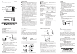
3. Instrument Layout
Line Probe
Earth Terminal
Press to Test Button
Function Switch
Fig.1
Guard Terminal
LED's for High&
Low Range Indication
Battery Compartment
Cover

5
CAUTION:
BE CAREFUL ABOUT HIGH VOLTAGE PRESENT ACROSS LINE
AND EARTH TERMINALS OF INSTRUMENT WHEN PRESS TO
TEST BUTTON IS OPERATED. MAKE SURE TO EARTH CIRCUIT
UNDER TEST. ALWAYS CONNECT EARTH TERMINAL OF
INSTRUMENT TO EARTH. THE BUZZER WILL KEEP SOUNDING
DURING INSULATION RESISTANCE MEASUREMENT.
4-1.Mechanical Zero Adjustment
With the function switch set at OFF position, adjust the meter
pointer to mark on the scale. Use a screwdriver to turn the
zero adjust screw located at the center of the front panel.
4-2.Battery Check
With the function switch set at BATT. CHECK position, operate the
press to test button. The batteries are good when the pointer stays
in BATT. GOOD area or to the right of this area. If not, replace them.
Note: Refrain from holding down or locking the press to
test button during this as it will result in current
consumption larger than insulation resistance
measurement while the batteries are still new.
4. Operating Instructions

6
4-3.Insulation Resistance Measurement
With the function switch set at OFF position, always connect the
circuit under test to earth. Attach the test lead to the earth terminal
of the instrument and connect to the earthed side of the circuit
under test. With the function switch set at M position for Model
3121 and 3122 or G position for Model 3123, place the line
probe in contact with the circuit under test and operate the press
to test button. When the green LED illuminates, read insulation
resistance on the outer scale(for high range). Use the inner scale
where the red LED illuminates. For insulation testing at 5000V and
10000V, read the black and red scales respectively (for Model
3123). After a test, release the press to test button and wait for
several seconds without disconnecting the line probe from the
circuit tested. This is intended to discharge the charge stored in the
circuit tested.
4-4.Continuous Measurement
Make sure that the circuit under test is earthed and that the test
lead attached to the earth terminal of the instrument is connected
to the earthed side of the circuit under test. Push the press to test
button and turn clockwise to lock for continuous measurement.
When making this measurement, good care must be taken against
the high voltage continuously present across the line and earth
terminals of the instrument.
Note: Make certain that the circuit under test does not
include components which will be damaged by the
high voltage applied.

7
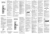
4-5.Use of Guard Terminal
Illustrated in Fig. 2 is an example of the insulation resistance
measurement of an electric wire. If the line probe is simply
connected to the wire conductor and the earth lead to the
immersion liquid container as shown, a measurement error will be
introduced as this results in the measurement of the combined
resistance of insulation resistance and the surface leakage
resistance at the cut end of the electric wire. In order to remove
this surface leakage current, wide a guard wire around the cut
end of the conductor and connect it to the guard terminal of the
instrument using the guard lead. Then, the surface leakage current
will bypass the indicating meter of the insulation resistance tester.
Fig.2

8
Remove the battery compartment cover by loosening the screw located
on the back of the housing case. Replace the whole battery pack. Alkaline
batteries are recommended where the instrument is used at a temperature
below the freezing point. The ordinary manganese batteries will deteriorate
below the freezing point.
For your information, optional adaptor Model 8020 is available to allow
Model 3121,3122 and 3123 to be connected to a recorder for recording
insulation resistance. It provides an output signal of 1 A/10mV DC.
5. Batttery Replacement
6. Cleaning Meter Cover
Do not try to remove dirt on the meter cover by rubbing hard with a dry
cloth. This can remove anti-electrostatic agent applied to the surface of the
surface of the meter cover.
When the meter reading is affected by electrostatic build up on the meter
cover, wipe the meter cover surface using a cloth dampened with off-the
shelf anti-static agent or detergent.
To avid possible deforming or discoloring, do not use solvents.
To clean the body of the instrument, use cloth dampened with detergent.
CAUTION
Never use paint thinner, benzene or other solutions containing solvents
for cleaning the instrument.
Otherwise, deforming or discoloring of the instrument body or the
meter cover may result.
Note:
Handle the instrument with care and follow the instructions in order
to maintain it in good condition for a long period of time.

9
Lifetime Limited Warranty
The attention to detail of this fine snap-around instrument is further
enhanced by the application of A.W. Sperry s unmatched service and
concern for detail and reliability. These A.W. Sperry snap-arounds are
internationally accepted by craftsmen and servicemen for their unmatched
performance. All A.W. Sperry s snap-around instruments are unconditionally
warranted against defects in material and workmanship under normal
conditions of use and service; our obligation under this warranty being
limited to repairing or replacing free of charge, at A.W. Sperry snap-around
instrument that malfunctions under normal operating conditions at rated
use. 1
Replacement procedure
Securely wrap the instrument and its accessories in a box or mailing bag
and ship prepaid to the address below. Be sure to include your name and
address, as well the name of the distributor, with a copy of your invoice
from whom the unit was purchased, clearly identifying the model number
and date of purchase.
A.W.SPERRY INSTRUMENTS INC.
ATT: Customer service dept.
2150 Joshua s Path, Suite 302,
Hauppauge, NY 11788
1The warranty is not applicable if the instrument has been: misused, abused,
subjected to loads in excess of specifications, has had unauthorized repair
or has been improperly assembled or used.
*Note: Recommended calibration interval should not exceed one year.
Calibration service charges are not covered terms and conditions of
warranty.

/