Toro Power Clear 721 R Snowthrower User manual
- Category
- Snow throwers
- Type
- User manual
This manual is also suitable for
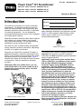
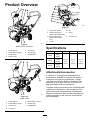
Toro Power Clear 721 R Snowthrower is designed to remove snow effectively from paved surfaces and other surfaces for traffic on residential or commercial properties. It features a powerful engine for efficient snow clearing, a durable auger system to break down even the toughest snow, and a chute control system that allows you to adjust the direction and distance of the snow discharge. The compact size of the snowthrower makes it easy to maneuver in tight spaces, and the adjustable skid shoes help to protect your driveway or sidewalk from damage.
Toro Power Clear 721 R Snowthrower is designed to remove snow effectively from paved surfaces and other surfaces for traffic on residential or commercial properties. It features a powerful engine for efficient snow clearing, a durable auger system to break down even the toughest snow, and a chute control system that allows you to adjust the direction and distance of the snow discharge. The compact size of the snowthrower makes it easy to maneuver in tight spaces, and the adjustable skid shoes help to protect your driveway or sidewalk from damage.


-
 1
1
-
 2
2
-
 3
3
-
 4
4
-
 5
5
-
 6
6
-
 7
7
-
 8
8
-
 9
9
-
 10
10
-
 11
11
-
 12
12
-
 13
13
-
 14
14
-
 15
15
-
 16
16
-
 17
17
-
 18
18
-
 19
19
-
 20
20
-
 21
21
-
 22
22
-
 23
23
-
 24
24


Toro Power Clear 721 R Snowthrower User manual
- Category
- Snow throwers
- Type
- User manual
- This manual is also suitable for
Toro Power Clear 721 R Snowthrower is designed to remove snow effectively from paved surfaces and other surfaces for traffic on residential or commercial properties. It features a powerful engine for efficient snow clearing, a durable auger system to break down even the toughest snow, and a chute control system that allows you to adjust the direction and distance of the snow discharge. The compact size of the snowthrower makes it easy to maneuver in tight spaces, and the adjustable skid shoes help to protect your driveway or sidewalk from damage.
Ask a question and I''ll find the answer in the document
Finding information in a document is now easier with AI
Related papers
-
Toro Power Clear 721 QZE Snowthrower User guide
-
Toro Powerlite Snowthrower User manual
-
Toro Power Clear 721 QZE Snowthrower User manual
-
-
Toro Power Clear 721 QZE Snowthrower User manual
-
Toro Power Clear 721 R-C Commercial Snowthrower User manual
-
-
-
-