Page is loading ...

Wattstopper
®
DLM Triple Relay with 0-10V Dimming Room Controller
DLM relais triple avec contrôleur de pièce de gradation 0-10 V
Relé triple DLM con controlador de regulación de habitación de 0 a 10 V
Quick Start Guide • Guide de démarrage rapide • Guía de inicio rápido
No: 23994 – 01/20 rev. 8
Catalog Numbers • Les Numéros de Catalogue • Números de Catálogo: LMRC-213/LMRC-213-347
Country of Origin: Made in China • Pays d’origine: Fabriqué en Chine • País de origen: Hecho en China
LMRC-213-U and LMRC-213-347 -U are BAA and TAA compliant (Product produced in the U.S.)
SPECIFICATIONS
Voltage
LMRC-213 Input Voltage ..Single Phase 120/230/240/277VAC, 50/60Hz
LMRC-213-347 Input Voltage................................ 347VAC, 50/60Hz
Load Requirements
LMRC-213 ..................................................... Not to exceed 20A total
Each relay rated for up to:
Incandescent. ....................................................20A @ 120VAC
Ballast ........................................................20A @ 120/277VAC
Motor .................................................................1Hp @ 120VAC
LMRC-213-347 ..............................................Not to exceed 15A total
Each relay rated for up to: Ballast/LED Driver ......15A @ 347VAC
Class 2 Dimming Output, 0-10V .....................sinks up to 100mA per channel
Output to DLM Local Network .............................. up to 250mA @ 24VDC
Connection to the DLM Local Network ................................. 4 RJ-45 ports
DLM Local Network characteristics when using LMRC-11x/2xx room
controllers:
Low voltage power provided over Cat 5e cable (LMRJ); max current
800mA. Supports up to 64 load addresses, 48 communicating
devices including up to 4 LMRC-10x series and/or LMPL-101
controllers and LPB-100. Free topology up to 1,000’ max.
Environment ...............................................................For Indoor Use Only
Operating Temperature ..............................32° to 158°F (0° to 70°C)
Storage Temperature ................................23° to 176°F (-5° to 80°C)
Relative Humidity ....................................5 to 95% (non condensing)
Patent Pending
UL/CUL listed under UL60730. The LMRC-213 is also Complementary
Listed to “Emergency Lighting Equipment”, (UL924) intended for Indoor
Dry Locations (does not apply to LMRC-213-347).
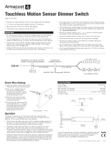
PLACEMENT EXAMPLE
This unit is pre-set for Plug n’ Go™ operation, adjustment
is optional.
For full operational details, adjustment and more features of the
product, see the DLM System Installation Guide provided with
Wattstopper room controllers, and also available at
www.legrand.us/Wattstopper.
Installation shall be in accordance with all applicable
regulations, local and NEC codes. Wire connections shall
be rated suitable for the wire size (lead and building wiring)
employed.
For Class 2 DLM devices and device wiring: To be connected
to a Class 2 power source only. Do not reclassify and install as
Class 1, or Power and Lighting Wiring.
IMPORTANT SAFEGUARDS
When using electrical equipment, basic safety precautions
should always be followed including the following:
a. READ AND FOLLOW ALL SAFETY INSTRUCTIONS.
b. Do not use outdoors.
c. Do not mount near gas or electric heaters.
d. Equipment should be mounted in locations and
at heights where it will not readily be subjected to
tampering by unauthorized personnel.
e. The use of accessory equipment not recommended by
the manufacturer may cause an unsafe condition.
f. Do not use this equipment for other than intended use.
g. Installation should be performed by qualified service
personnel.
SAVE THESE INSTRUCTIONS
Corner Mount
Occupancy
Sensor
Switch/
Dimmer
Ceiling Mount
Occupancy
Sensor
J Box
To
Load
DLM Local Network
(low voltage, Class 2)
LMRJ cables
LMRC-21x
Room
Controller
To 0-10V
Dimming Ballast
Daylighting
Sensor
CAUTION: TO CONNECT A COMPUTER TO THE DLM LOCAL NETWORK USE THE
LMCI-100. NEVER CONNECT THE DLM LOCAL NETWORK TO AN ETHERNET
PORT – IT MAY DAMAGE COMPUTERS AND OTHER CONNECTED EQUIPMENT.

2
CONNECTIVITY
Both Room Controllers communicate to all other DLM devices connected to the DLM Local Network. Connections shown are for
example only. The low voltage LMRJ cables can connect to any DLM device with an open RJ45 receptacle.
All line voltage wiring is #12 AWG. For the LMRC-213, each relay is rated for up to 20A; total load not to exceed 20A. For the
LMRC-213-347 each relay is rated for up to 15A; total load not to exceed 15A. Specified load types can connect to any load relay.
Do not connect different load types to the same relay. For dimming ballasts or drivers, connect the 0-10V control wires to the 0-10V
terminals that match the load relay output connection.
Line
Voltage
Room
Controller
Deep J-Box
Daylight Sensor
DimmerSwitch
Corner Mount
Sensor
Ceiling Mount
Sensor
DLM Local Network
Low Voltage
LMRJ Cables
Load
Examples
(any relay)
A
Line/Hot
Black wire
Neutral
White wire
Red wire to Load A
Blue wire
to Load C
Yellow wire to Load B
Switched with
0-10 Volt control
Dimming Ballast
LED Driver, etc.
C
Switched
Ballast
B
0-10V Dimming control wires (available for each load)
Switched
Earth Ground/Green wire
USING THE LMRC-213 WITH EMERGENCY LIGHTING
When used with an ELCU
Wattstopper recommends using an ELCU device. In
this scenario, the LMRC-213’s 0-10VDC dimming circuit
is connected to and alters the light level of both normally
powered lighting loads and emergency powered lighting
loads. The 0-10V signal is generated individually by each
ballast or driver when they are powered.
When Normal Power is available:
When Normal Power is available and the normal load
has been turned off by any DLM device (OS, photocell, or
dimmer switch, or LMRC override button), the ELCU will
turn off the Emergency Load as well.
When Normal Power is unavailable:
When normal power to the room controller fails for any
reason, the 0-10VDC dimming circuit in the LMRC-213 will
revert to an open circuit. Since no device is controlling the
0-10V circuit, any fixture that is fed by emergency power
will go full on. Fixtures fed by normal power will of course
be off since there is no power available for their operation.
NOTE: If additional normal and emergency lighting loads
are controlled by the LMRC-213, a separate ELCU
device is needed.
When no ELCU is used:
In this scenario, emergency lighting cannot be turned
on or off by a DLM device, only dimmed. The normal
lighting load has full control. As in the example with the
ELCU, if normal power fails, the emergency load will go
full on. If any Emergency Circuits are fed or controlled
from a panel, they must be located electrically where
fed from a UPS, generator, or other guaranteed
source of power during emergency and power outage
situations.
NOTE: If you use only a single set of 0-10VDC wires,
the emergency load will dim the same as the
normal load (when not in an emergency power
only mode).
09860r1
Cir.#_______
Emergency
Power
Remote
Activation
Normal
Power
Push to Test
R8.5
mm
Circle
CUT-OUT
EMERGENCY CIRCUIT
Cut Jumper Loop
to use with
normally closed
- Test switch
- Fire alarm panel
- Security panel
- Other
Emergency Power In (Black)
Emergency Neutral Gray)
Emergency Power Out (Red)
Normal Neutral (White)
Normal Switch Sense (Red)
Normal
Power
Sense
(Black)
Normal
Lighting
Emergency Line
“Always On”
Emergency Neutral
Emergency
Lighting
Unswitched
Line (Black)
Neutral
(White)
Red
Gray
Violet
Gray
Violet
Gray
Violet
Neutral
To DLM Devices
Class 2 0-10V
Control Wiring
Ground
(Green)
To DLM Devices
Ground
(Green)
Unswitched
Line (Black)
Neutral
(White)
Red
Neutral
Gray Violet
Class 2 0-10V
Control Wiring
Normal
Lighting
Violet
Gray
Emergency Neutral
(White)
Emergency Line
“Always On”
Emergency
Lighting

3
MOUNTING THE CONTROLLER
The room controller mounts as the cover for a four square deep junction
box. After connecting the load and line wires, secure the LMRC-213 to the
cover tabs on a deep junction box using two screws.
Cover a 4”x 4”x 2 1/8”deep
(minimum) box.
Line
J-Box
Load
Remove rubber jack covers to use RJ45 receptacles.
Leave covers in place for all unused receptacles.
Gray (-)
Violet (+)
Attaching LMRJ Cables 0-10V Connections
PLUG N’ GO OPERATION (PNG)
Plug n’ Go supports the most energy efficient control strategy.
For example, if at least two loads, one switch and one occupancy
sensor are connected to the DLM local network, the system
operates load A as Automatic ON, Automatic OFF and load B as
Manual-On, Automatic-Off.
See DLM device Quick Start Guides to determine how each
device affects the PNG operation of the LMRC-213 and the
LMRC-213-347.
Load Control Arbitration
To take full advantage of automatic PnG configuration, review these simple rules about load control
arbitration.
After the room controllers are connected to the DLM Local Network and powered up they
automatically negotiate to determine which controller becomes the Master and the load numbers for
each relay on the DLM Local Network.
The Master is the controller with the most load relays and the highest serial number. The LMRC-213 and
the LMRC-213-347 Room Controllers each have three load relays.
In a DLM local network with only LMRC-213 or LMRC-213-347 Room Controllers, the Room
Controller with the highest serial number is the Master, carrying Loads 1, 2, and 3. The next highest
serial number would have Loads 4, 5, and 6, and so forth.
UNIT ADJUSTMENT - PUSH N’ LEARN (PNL)
Load Selection Procedure.
A configuration button (Config) allows access to our patented Push n’ Learn™ technology to change binding relationships between sensors,
switches and loads.
Step 1 Enter Push n’ Learn.
Press and hold the Config button (on any DLM device) for 3 seconds.
• The red LED on the Controller begins to blink. When you release the button, the red LEDs on other
communicating devices connected to the DLM Local Network begin to blink. They continue to blink until
you exit PnL mode.
• All loads in the room turn OFF immediately after entering PnL, then one load will turn ON. This is Load
#1, which is bound to switch button #1 and occupancy sensors as part of the Plug n’ Go factory default
setting. All switch buttons and sensors that are bound to this load have their blue LED solid ON.
Load A
ON/OFF/Dim
Load B
ON/OFF/Dim
Load C
ON/OFF/Dim
Blue LED
ON when load is
ON.
Load button:
Press & release
for ON/OFF.
Press & hold to
Dim.
WARNING: TURN THE POWER OFF AT THE
CIRCUIT BREAKER BEFORE WIRING.
Cong button & red LED
0341373638
Serial
Number
Room
Controller
Load
Control
LMRC-213
4
5
0473956423
Master
0341373638
LMRC-213
1
2
0473956377
6
3
A
B
C
A
B
C

4
Step 2 Load selection.
Press and release the Config button to step through the loads connected to the DLM Local Network. As each load turns ON note the
devices (switch buttons and sensors) that are showing a bright solid blue LED. These devices are currently bound to the load that is ON.
The blue LED on the room controller or plug load controller connected to the load is also lit.
• To unbind a switch or dimmer button from a load, press the switch button while its blue LED is ON bright. The blue LED goes dim
to indicate the button no longer controls the load that is currently ON.
• To unbind an occupancy sensor, press the up () or down () adjustment button while its blue LED is ON. The blue LED turns
OFF to indicate the sensor no longer controls the load that is currently ON.
Pressing the switch or up () or down () button again while the load is ON rebinds the load to the button or sensor and the blue LED
illuminates brightly.
Step 3 Exit Push n’ Learn.
Press and hold the Config button until the red LED turns OFF, approximately 3 seconds.
TROUBLESHOOTING
LEDs on a switch or sensor
don’t light.
1. Check to see that the the device is connected to the DLM Local Network.
2. Check for 24VDC input to the device: Plug in a different DLM device at the device location. If the
device does not power up, 24VDC is not present.
• Check the high voltage connections to the room controller and/or plug load controller(s).
• If high voltage connections are good and high voltage is present, recheck DLM Local Network
connections between the device and the room controller(s).
The wrong lights and plug
loads are controlled.
1. Configure the switch buttons and sensors to control the desired loads using the Push n’ Learn
adjustment procedure.
LEDs turn ON and OFF but
load doesn’t switch.
1. Make sure the DLM local network is not in PnL.
2. Check load connections to room controllers and/or plug load controllers.
Lamps do not dim, or
lamps drop out at low dim
levels.
1. Make sure a 0-10V dimming ballast and rapid start sockets are installed per the ballast
manufacturer’s recommendation. Shunted sockets are typically not acceptable.
2. Check wiring per ballast manufacturer’s instructions.
This device complies with part 15 of the FCC Rules. Operation is subject to the following two conditions: (1)This device may not cause
harmful interference, and (2) this device must accept any interference received, including interference that may cause undesired operation.
NOTE: This equipment has been tested and found to comply with the limits for a Class A digital device, pursuant to part 15 of the FCC Rules.
These limits are designed to provide reasonable protection against harmful interference when the equipment is operated in a commercial
environment. This equipment generates, uses, and can radiate radio frequency energy and, if not installed and used in accordance with the
instruction manual, may cause harmful interference to radio communications. Operation of this equipment in a residential area is likely to
cause harmful interference in which case the user will be required to correct the interference at his own expense.
/