Tripp Lite SmartPro® LCD UPS Systems Owner's manual

Category
Uninterruptible power supplies (UPSs)
Type
Owner's manual
Owner’s Manual
1
SmartPro
®
LCD UPS Systems
Models:
SMART1200LCD
(Series Number: AGOM5515)
Important Safety Instructions 2
Quick Installation 4
Basic Operation 6
UPS On/Off 6
LCD 6
LCD Features 6
Display Power Conditions 6
Enable/Disable Alarm 6
LCD Brightness 7
Self-test 7
Power Sensitivity 7
Scroll Control 8
External Battery Settings 8
Error Messages 8
Features 9
Battery Replacement 10
Storage and Service 12
Product Registration 12
Español 14
Français 27
SMART1500LCD
(Series Number: AG-8869)
SMART1500LCDXL
(Series Number: AGSM8191)
Not suitable for mobile applications
1111 W. 35th Street, Chicago, IL 60609 USA • www.tripplite.com/support
Copyright © 2018 Tripp Lite. All rights reserved.
PROTECT YOUR INVESTMENT!
Register your product for quicker service
and ultimate peace of mind.
You could also win an
ISOBAR6ULTRA surge protector—
a $100 value!
www.tripplite.com/warranty
18-11-160-9336B5.indb 1 12/17/2018 4:35:56 PM
Important Safety Instructions
2
SAVE THESE INSTRUCTIONS
This manual contains instructions and warnings that should be followed during the
installation, operation and storage of this product. Failure to heed these warnings
may affect your warranty.
UPS Location Warnings
Install your UPS indoors, away from excess moisture or heat, conductive contaminants,
dust or direct sunlight.
For best performance, keep the indoor temperature between 32º F and 104º F
(0º C and 40º C).
Leave adequate space around all sides of the UPS for proper ventilation.
Do not mount unit with its front or rear panel facing down (at any angle). Mounting
in this manner will seriously inhibit the unit’s internal cooling, eventually causing
product damage not covered under warranty.
UPS Connection Warnings
Connect your UPS directly to a properly grounded AC power outlet. Do not plug the UPS
into itself; this will damage the UPS.
Do not modify the UPS’s plug, and do not use an adapter that would eliminate the UPS’s
ground connection.
Do not use extension cords to connect the UPS to an AC outlet.
If the UPS receives power from a motor-powered AC generator, the generator must provide
clean, filtered, computer-grade output.
The mains socket outlet that supplies the UPS should be easily accessible and located
near the UPS.
• The building installation provides short circuit back-up protection.
EMI Filter
Surge Protecon
Inverter
Charger
Control
Transformer
Line Cutoff Relay
Boost 1 Relay
Cut Relay
AC In
AC Out
USB Com Port
Serial Com Port
+
Internal
Baery
External Baery
Connector*
LCD Display, Switches
Circuit Breaker
Teleprotect Circuit
*If applicable
18-11-160-9336B5.indb 2 12/17/2018 4:35:57 PM
Important Safety Instructions
3
Equipment Connection Warnings
Use of this equipment in life support applications where failure of this equipment can
reasonably be expected to cause the failure of the life support equipment or to significantly
affect its safety or effectiveness is not recommended.
Do not connect surge protectors or extension cords to the output of your UPS. This might
damage the UPS and may affect the surge protectors and UPS warranties.
Connect the UPS to an outlet that is adequately protected against excess currents, short
circuits and earth faults as part of the building installation.
Battery Warnings
Your UPS does not require routine maintenance. Do not open your UPS for any reason.
There are no user-serviceable parts inside.
Batteries can present a risk of electrical shock, chemical hazard and burn from high short-
circuit current. Observe proper precautions. Do not dispose of the batteries in a fire. Do
not open the
UPS or batteries. Do not short or bridge the battery terminals with any object. Unplug and
turn off the UPS before performing battery replacement. Use tools with insulated handles.
There are no user-serviceable parts inside the UPS. Battery replacement should be
performed only by authorized service personnel using the same number and type of
batteries (Sealed Lead-Acid). The batteries are recyclable. Refer to your local codes for
disposal requirements or visit http://www.tripplite.com/support/recycling-program for
recycling information. Tripp Lite offers a complete line of UPS System Replacement
Battery Cartridges (R.B.C.).Visit Tripp Lite on the Web at
http://www.tripplite.com/products/battery-finder/ to locate the specific
replacement battery for your UPS.
• When adding an external battery pack, connect only a Tripp Lite recommended battery pack
of the correct voltage and type. Do not connect or disconnect the external battery pack
when the UPS is operating on battery power. Visit Tripp Lite on the Web at
www.tripplite.com/support to locate the specific battery for your UPS.
UPS and Battery Recycling
Please recycle Tripp Lite Products. The batteries used in Tripp Lite products are
sealed Lead-Acid batteries. These batteries are highly recyclable. Please refer to
your local codes for disposal requirements.
You can call Tripp Lite for recycling info at 1.773.869.1234.
You can go to the Tripp Lite Website for up-to-date information on recycling the
batteries or any Tripp Lite product. Please follow this link:
http://www.tripplite.com/support/recycling-program/
18-11-160-9336B5.indb 3 12/17/2018 4:35:57 PM
4
1. Place the UPS in a horizontal or
vertical (tower) position.
To install the UPS in a 4-post or 2-post
rack, remove the mounting hole covers
from the top and bottom sides of the
UPS
A
. To install the UPS in a 4-post
rack, attach the mounting ears to each
side of the UPS using the included
hardware
B
. To install the UPS in a
2-post rack, attach the mounting ears to
each side of the UPS using the included
hardware
C
. With the help of an
assistant (if needed), lift the UPS and
attach it to a standard rack with user-
supplied hardware.
CAUTION: If the UPS is
installed in a rack, allow at
least 2 cm (0.75 in.) clearance
above and below the unit. If
the UPS is placed on a flat
surface, do NOT stack any
other object directly on top of
the unit.
The UPS will stand in a tower position
without the aid of the included hardware.
For increased stability, Tripp Lite
recommends attaching the included
hardware as shown in diagram
D
. In
either position, the user must determine
the fitness of hardware and procedures
before installation.
Note: The UPS and its included hardware are
designed for use with common rack types and
may not be appropriate for all applications.
The LCD may be rotated to match the
orientation of the UPS. To rotate, first
carefully insert a small tool into the slots
located on the each side of the LCD.
Remove the LCD from the UPS housing,
then rotate and press it back into place.
CAUTION: To safely balance
the UPS in a vertical position,
make sure the LCD is located
at the top of the front panel.
Quick Installation
C
B
A
D
18-11-160-9336B5.indb 4 12/17/2018 4:35:58 PM
5
Quick Installation
2. Plug the UPS into a properly grounded outlet outlet.*
After plugging the UPS into a wall outlet, push the ON/OFF button for one second to turn
on the UPS (see Basic Operation section for more information).
Note: The UPS will not turn on automatically in the presence of live utility power.
*Use an outlet that does not share a circuit with a heavy electrical load, such as an air conditioner or
refrigerator.
3. Plug equipment into the UPS.
The UPS is designed to support electronic equipment only. Connected equipment will
overload the UPS if the total VA ratings for all the equipment connected to the outlets
exceeds the UPS Output Capacity. To find VA ratings, look at equipment nameplates. If
the equipment is listed in amps, multiply the number of amps by 120 volts to determine
VA. (Example: 1 amp × 120 volts = 120 VA). If unsure whether the outlets are
overloaded, run a self-test (see MUTE/TEST Button description for more information).
4. Optional – Connect Communication Cables.
The UPS includes USB and RS-232 communication ports, as well as Tel/DSL/Ethernet
and Coaxial surge protection jacks. These connections are optional, and the UPS will
function properly without these connections.
Not compatible with PoE (Power over Ethernet) applications.
CAUTION: The UPS must be plugged into a live AC outlet and powered on
for 24 hours after initial installation to fully charge the internal battery.
Connected equipment will receive utility-supplied AC power (if present)
immediately after the UPS is plugged in and turned on, but connected
equipment will not receive full battery backup in the event of a blackout or
severe brownout, unless the internal battery is fully charged.
18-11-160-9336B5.indb 5 12/17/2018 4:35:58 PM
6
UPS ON/OFF
Plug the UPS into a grounded outlet.
Turn the UPS on: Press and hold the
MODE
button for 2 seconds. The UPS alarm will beep
once briefly after 2 seconds have passed.
Plug equipment into the UPS: Your UPS is designed to support electronic equipment
only. You will overload the UPS if the total VA ratings for all the equipment you connect to
the “Battery, Surge and Noise Protected” outlets exceeds the UPS’s Output Capacity. To
estimate your equipment’s power requirements, look on the nameplate. If the equipment
is listed in amps, multiply the number of amps by 120 to determine VA, (Example: 1 amp
x 120 = 120 VA). Your UPS is fully loaded when the display indicates 100% load.
Turn the UPS off: Press and hold the
MODE
button for 2.5 seconds. The UPS alarm will
beep once after 2.5 seconds have passed.
LCD
The LCD indicates a variety of UPS operational conditions. All descriptions apply when the
UPS is plugged into an AC outlet and turned on. The LCD can be rotated for easy viewing,
regardless of whether the UPS is in a horizontal or vertical (“tower”) position. To rotate the
display, insert a small tool in the slots on the sides of the display to pop it out of the UPS
housing; rotate the display, and snap it back into the UPS housing.
LCD Features
Tap the
MODE
button to advance from one display to the next. Use the
MUTE
button to toggle
settings for Power Sensitivity Control, External Battery Setting Control, Scroll Control, Alarm,
LCD Brightness and Self-test functions. The last option displayed before navigating away from
this menu option will be the selected setting. When the preferred setting has been selected,
continue by pressing the
MODE
button. If the screen is idle for 20 seconds, the LCD will return
to the home screen, retaining the last selected settings.
Display Power Conditions
Use the
MODE
button to advance through
power conditions.
1. Voltage In
2. Voltage Out
3. Estimated Runtime (in minutes)
4. Load %
5. Load Wattage*
6. Battery Capacity %
* Load Wattage is displayed in watts up to “999”,
and then will be displayed in Kilowatts.
Enable/Disable Alarm
Tap the
MODE
button repeatedly to advance to the LCD screen featuring the icon. Press the
MUTE
button to select ON or OFF alarm mode settings. The last option displayed before
navigating away from this menu option will be the selected setting.
Basic Operation
INPUT
1 2
RUNTIME
MIN
3
4
5
6
18-11-160-9336B5.indb 6 12/17/2018 4:35:59 PM
Basic Operation
7
LCD Brightness
Tap the
MODE
button repeatedly to advance to the LCD Brightness screen marked “LCD”. Press
the
MUTE
button to select Medium Backlight (default), High Backlight or Dim Backlight. The last
option displayed before navigating away from this menu option will be the selected setting.
Note: After 2 minutes of inactivity, the backlight will revert to the Dim setting until a button is pressed.
Self-test
Tap the
MODE
button repeatedly to advance to the TEST BATT screen. Press the
MUTE
button to
initiate the test. The test will last approximately 10 seconds as the UPS switches to battery to
test the capacity with a load. Upon completion of the test, the screen will indicate PAS or
BAD (pass or bad) for 20 seconds, then return to the home screen. Connected equipment
can remain on during the test. Do not unplug your UPS, this will remove safe electrical
grounding.
Power Sensitivity
Tap the
MODE
button repeatedly to advance to Sensitivity screen, as shown here:
Press the
MUTE
button to advance through the options. The last option displayed, before
navigating away from this menu option, will be the selected setting.
This setting is normally set to 100%, which enables the UPS to protect against waveform
distortions in its AC input. When such distortion occurs, the UPS will normally switch to
providing PWM sine wave power from its battery reserves for as long as the distortion is
present. In some areas with poor utility power or where the UPS’s input power comes from a
backup generator, frequent brownouts and/or chronic waveform distortion could cause the
UPS to switch to battery too often, draining its battery reserves. You may be able to reduce
how often your UPS switches to battery due to waveform distortion or brownouts by
experimenting with different settings. As the setting is reduced, the UPS becomes more
tolerant of variations in its input power’s AC waveform.
Note: When experimenting with different settings, operate connected equipment in a safe test mode so
that the effect on the equipment of any waveform distortions in the UPS’s output can be evaluated
without disrupting critical operations. The experiment should last long enough to assure that all expected
line conditions are encountered.
18-11-160-9336B5.indb 7 12/17/2018 4:35:59 PM
Basic Operation
8
Scroll Control
Tap the
MODE
button repeatedly to advance to the Scroll screen as shown here:
Press the
MUTE
button to advance to the next available option. The last option displayed,
before navigating away from this menu option, will be the selected setting.
This display option allows the user to select the option to automatically scroll each operating
condition of the UPS (such as Input Voltage, Output Voltage and Runtime) automatically.
Notes:
1. Each condition is displayed in 2 second intervals.
2. If a button is pressed while Scroll Mode is enabled, the scroll function will pause for 10 seconds to
allow the user to manually make menu selections.
External Battery Setting Control (XL model only)
Tap the
MODE
button repeatedly to advance to the External Battery screen, as shown here:
Press the
MUTE
button to advance to the next available option. The last option displayed,
before navigating away from this menu option, will be the selected setting.
Note: The Battery Runtime calculation is based on this setting.
This feature setting allows the user to configure the UPS for use with an External Battery Pack
or without an External Battery Pack. The Runtime will be automatically reconfigured.
Note: Battery Packs cannot be daisychained. Only one Battery Pack can be attached to the UPS.
Error Messages
In the event the UPS battery requires replacement, the icon will flash, as well as the
icon. If there is an overload, the , , and icons will flash simultaneously along with
a numeric read out of the load percentage.
BAT T ERYEX T ERNAL
BAT T ERYEX T ERNAL
18-11-160-9336B5.indb 8 12/17/2018 4:35:59 PM
9
Features
MODE
UPS Features
ON/OFF/MODE Button: Press and hold for 2 seconds to turn on the
UPS and 2.5 seconds to turn the UPS off. When the UPS is on, tap
this button repeatedly to advance through LCD screens. If utility power
is absent, pressing and holding this button for 2.5 seconds will
“cold-start” the UPS; i.e. turn it on and supply power to the outlets
from its batteries.
MUTE/ENTER Button: Use this button to toggle selection options for:
self-test, enable/disable alarm, LCD brightness, Sensitivity Control,
Scroll Control and the External Battery Setting Control. This button
can also be used to temporarily mute an active alarm by briefly
pressing it.
Tel/DSL Line Protection Jacks: These jacks protect equipment
against surges over a single phone line. Connecting your equipment
to these jacks is optional. Your UPS will work properly without this
connection. An RJ-11 cable is included with your UPS.
USB and RS-232 Communication Ports: These ports can connect
your UPS to any computer for automatic file saves and unattended
shutdown in the event of a power failure. Use with Tripp Lite’s
PowerAlert Software (available as a FREE download at
www.tripplite.com) and appropriate USB or DB9 cable. Both a USB
and a DB9 cable are included with your UPS.
Notes:
1. This connection is optional. The UPS will work properly without this
connection.
2. This UPS System provides basic communication compatibility with most
integrated Windows
®
, Macintosh
®
, and Linux
®
power management applications.
Battery Backup Protected/Surge Protected Outlets: Provide both
battery backup and surge protection. Plug your computer, monitor and
other critical equipment into these outlets.
Note: Do not plug laser printers into the UPS.
Removable Mounting Hardware: Adapts the UPS to either tower or
rack-mount (2U) applications.
External Battery Connector (XL model only): Use to connect a
Tripp Lite external battery pack for additional runtime. Only use the
Tripp Lite BP24V15RT2U external battery pack (rated 24Vdc, 14Ahr
with overcurrent protection). Refer to instructions available with the
battery pack for complete connection information and safety warnings.
Note: Visit Tripp Lite on the Web at www.tripplite.com/support to locate the
specific battery for your UPS.
Resettable Input Circuit Breaker: Protects your electrical circuit
from overcurrent draw from the UPS load. If this breaker trips, remove
some of the load, then reset it by pressing it in.
MUTE
18-11-160-9336B5.indb 9 12/17/2018 4:36:00 PM
10
Battery Replacement
Under normal conditions, the original battery in your UPS will last several years. Battery
replacement should only be performed by qualified personnel. Refer to “Battery Warnings” in
the Important Safety Warnings section for complete battery safety information.
The SMART1200LCD UPS system requires a Tripp Lite RBC1200 replacement battery
cartridge. The SMART1500LCD UPS system requires a Tripp Lite RBC1500 replacement
battery cartridge. For the SMART1500LCDXL model, only Tripp Lite BP24V15RT2U external
battery pack (rated 24Vdc, 14Ahr with overcurrent protection) should be connected to the
external battery pack connector. For further information about replacement compatibility and
ordering, visit Tripp Lite on the Web at http://www.tripplite.com/products/battery-finder/
To Replace the Batteries:
1. Remove the retaining screw located on
the bottom of the unit.
2. Carefully pull the bottom panel away from
the UPS.
3. Disconnect the positive (red) and negative
(black) connectors and carefully remove
the old battery from the unit.
18-11-160-9336B5.indb 10 12/17/2018 4:36:02 PM
11
Battery Replacement
4. Carefully place the new batteries into the
UPS and connect the positive (+) (red)
connectors and negative (-) (black)
connectors.
5. Reattach the bottom panel and secure
using the retaining screw removed in
step 1.
18-11-160-9336B5.indb 11 12/17/2018 4:36:02 PM
Storage and Service
Storage
To avoid battery drain, all connected equipment should be turned off and disconnected from
the UPS. Press and hold the
MODE
button for 2.5 seconds. Your UPS will be completely turned
off (deactivated), and will be ready for storage. If you plan on storing your UPS for an
extended period, fully recharge the UPS batteries every three months. Plug the UPS into a
live AC outlet, turn it on by pressing and holding the
MODE
button for 2 seconds, and allow the
batteries to recharge for 4 to 6 hours. If you leave your UPS batteries discharged for a long
period of time, they will suffer a permanent loss of capacity.
Service
A variety of Extended Warranty and On-Site Service Programs are available from Tripp Lite.
For more information on service, visit www.tripplite.com/support. Before returning your
product for service, follow these steps:
1. Review the installation and operation procedures in this manual to insure that the service
problem does not originate from a misreading of the instructions.
2. If the problem continues, do not contact or return the product to the dealer. Instead, visit
www.tripplite.com/support.
3. If the problem requires service, visit www.tripplite.com/support and click the Product
Returns link. From here you can request a Returned Material Authorization (RMA) number,
which is required for service. This simple on-line form will ask for your unit’s model and
serial numbers, along with other general purchaser information. The RMA number, along
with shipping instructions will be emailed to you. Any damages (direct, indirect, special or
consequential) to the product incurred during shipment to Tripp Lite or an authorized Tripp
Lite service center is not covered under warranty. Products shipped to Tripp Lite or an
authorized Tripp Lite service center must have transportation charges prepaid. Mark the
RMA number on the outside of the package. If the product is within its warranty period,
enclose a copy of your sales receipt. Return the product for service using an insured
carrier to the address given to you when you request the RMA.
Visit www.tripplite.com/warranty today to register your new Tripp Lite product. You’ll be automatically entered into
a drawing for a chance to win a FREE Tripp Lite product! *
* No purchase necessary. Void where prohibited. Some restrictions apply. See website for details.
FCC Part 68 Notice (United States Only)
If your Modem/Fax Protection causes harm to the telephone network, the telephone company may temporarily
discontinue your service. If possible, they will notify you in advance. If advance notice isn’t practical, you will be
notified as soon as possible. You will be advised of your right to file a complaint with the FCC. Your telephone
company may make changes in its facilities, equipment, operations or procedures that could affect the proper
operation of your equipment. If it does, you will be given advance notice to give you an opportunity to maintain
uninterrupted service. If you experience trouble with this equipment’s Modem/Fax Protection, please visit www.
tripplite.com/support for repair/warranty information. The telephone company may ask you to disconnect this
equipment from the network until the problem has been corrected or you are sure the equipment is not
malfunctioning. There are no repairs that can be made by the customer to the Modem/Fax Protection. This
equipment may not be used on coin service provided by the telephone company. Connection to party lines is
subject to state tariffs. (Contact your state public utility commission or corporation commission for information.)
Product Registration
12
18-11-160-9336B5.indb 12 12/17/2018 4:36:02 PM
Product Registration
FCC Notice, Class B
This device complies with part 15 of the FCC Rules. Operation is subject to the following two conditions: (1) This
device may not cause harmful interference, and (2) this device must accept any interference received, including
interference that may cause undesired operation.
Note: This equipment has been tested and found to comply with the limits for a Class B digital device, pursuant
to part 15 of the FCC Rules. These limits are designed to provide reasonable protection against harmful
interference in a residential installation. This equipment generates, uses and can radiate radio frequency energy
and, if not installed and used in accordance with the instructions, may cause harmful interference to radio
communications. However, there is no guarantee that interference will not occur in a particular installation. If this
equipment does cause harmful interference to radio or television reception, which can be determined by turning
the equipment off and on, the user is encouraged to try to correct the interference by one or more of the
following measures:
Reorient or relocate the receiving antenna.
Increase the separation between the equipment and receiver.
Connect the equipment into an outlet on a circuit different from that to which the receiver is connected.
Consult the dealer or an experienced radio/TV technician for help.
Any changes or modifications to this equipment not expressly approved by Tripp Lite could void the user’s
authority to operate this equipment.
Equipment Attachment Limitations
(models with the Industry Canada label in Canada only)
NOTICE: The Industry Canada label identifies certified equipment. This certification means that the equipment
meets the telecommunications network protective, operational and safety requirements as prescribed in the
appropriate Terminal Equipment Technical Requirements Document(s). The Department does not guarantee the
equipment will operate to the user’s satisfaction.
Before installing this equipment, users should ensure that it is permissible to be connected to the facilities of the
local telecommunications company. The equipment must also be installed using an acceptable method of
connection. The customer should be aware that the compliance with the above conditions might not prevent
degradation of service in some situations.
Repairs to certified equipment should be coordinated by a representative designated by the supplier. Any repairs
or alterations made by the user to this equipment, or equipment malfunctions, may give the telecommunications
company cause to request the user to disconnect the equipment.
Users should ensure for their own protection that the electrical ground connections of the power utility, telephone
lines and internal metallic water pipe system, if present, are connected together. This precaution may be
particularly important in rural areas. Caution: Users should not attempt to make connections themselves, but
should contact the appropriate electric inspection authority, or electrician, as appropriate.
Not compatible with PoE (Power over Ethernet) applications.
Regulatory Compliance Identification Numbers
For the purpose of regulatory compliance certifications and identification, your Tripp Lite product has been
assigned a unique series number. The series number can be found on the product nameplate label, along with all
required approval markings and information. When requesting compliance information for this product, always
refer to the series number. The series number should not be confused with the marketing name or model number
of the product.
Tripp Lite has a policy of continuous improvement. Product specifications are subject to change without notice.
Note on Labeling
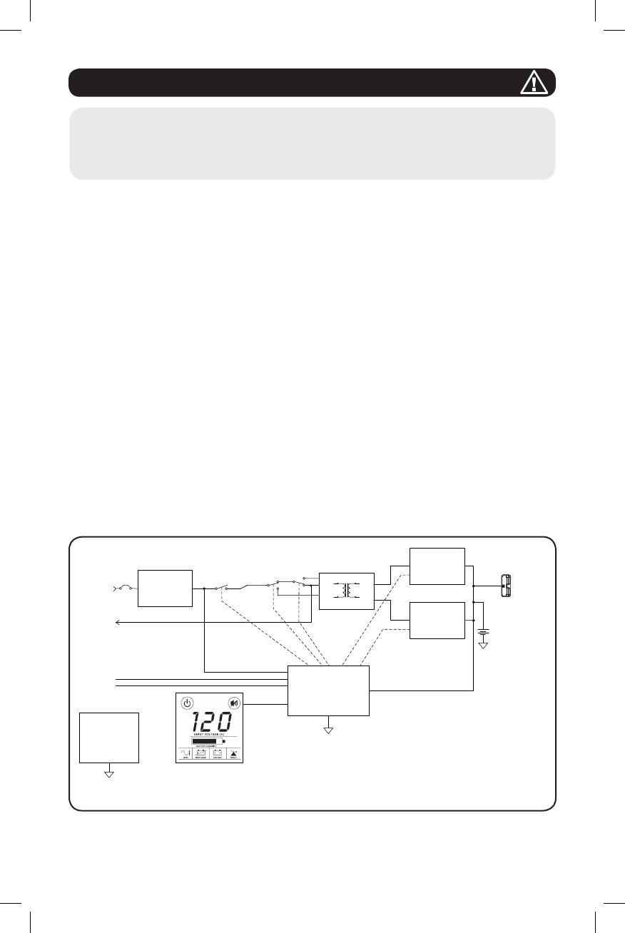
Two symbols are used on the label.
V~ : AC Voltage
V : DC Voltage
13
1111 W. 35th Street, Chicago, IL 60609 USA • www.tripplite.com/support
18-11-160-9336B5.indb 13 12/17/2018 4:36:03 PM
40
18-11-160 93-36B5_RevB
1111 W. 35th Street, Chicago, IL 60609 USA • www.tripplite.com/support
18-11-160-9336B5.indb 40 12/17/2018 4:36:10 PM
  • Page 1 1
  • Page 2 2
  • Page 3 3
  • Page 4 4
  • Page 5 5
  • Page 6 6
  • Page 7 7
  • Page 8 8
  • Page 9 9
  • Page 10 10
  • Page 11 11
  • Page 12 12
  • Page 13 13
  • Page 14 14
  • Page 15 15
  • Page 16 16
  • Page 17 17
  • Page 18 18
  • Page 19 19
  • Page 20 20
  • Page 21 21
  • Page 22 22
  • Page 23 23
  • Page 24 24
  • Page 25 25
  • Page 26 26
  • Page 27 27
  • Page 28 28
  • Page 29 29
  • Page 30 30
  • Page 31 31
  • Page 32 32
  • Page 33 33
  • Page 34 34
  • Page 35 35
  • Page 36 36
  • Page 37 37
  • Page 38 38
  • Page 39 39
  • Page 40 40

Tripp Lite SmartPro® LCD UPS Systems Owner's manual

Category
Uninterruptible power supplies (UPSs)
Type
Owner's manual

Ask a question and I''ll find the answer in the document

Finding information in a document is now easier with AI