Schumacher 260-9513 125A Automatic Battery Charger/Engine Starter MF187 Owner's manual
- Category
- Car battery chargers
- Type
- Owner's manual

To Reduce The Risk Of Injury, User Must Read And
Understand Operator’s Manual. Save These Instructions For Future Reference.
260-9513
0099002249-00
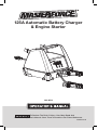
125A Automatic Battery Charger
& Engine Starter

TABLE OF CONTENTS
Safety Symbols ...............................................................................Page 3
Safety Information ..........................................................................Page 4
Important Safety Instructions .......................................................Page 5
Personal Safety Precautions..........................................................Page 5
Preparing To Charge .......................................................................Page 6
Charger Location ............................................................................Page 6
DC Connection Precautions ..........................................................Page 6
Follow These Steps When Battery Is Installed In Vehicle ............Page 6
Follow These Steps When Battery Is Outside Vehicle .................Page 7
Grounding and AC Power Cord Connections ..............................Page 7
Assembly Instructions ....................................................................Page 8
Control Panel ..................................................................................Page 8
Operating Instructions .................................................................... Page 9
Display Messages ........................................................................Page 12
Maintenance and Care .................................................................Page 13
Troubleshooting ............................................................................Page 13
Specifications ...............................................................................Page 14
Warranty ........................................................................................Page 15

Page 3
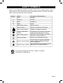
SAFETY SYMBOLS
Some of the following symbols may be used on your charger. Please study
them and learn their meaning. Proper interpretation of these symbols will allow
better and safer operation of the charger.
Symbol Name Designation/Explanation
V Volts Voltage
A Amperes Current
Hz Hertz Frequency
W Watts Power
~ Alternating current Type of current
Direct current Type or characteristic of current
Class II construction Double-insulated construction
Read the operator’s
manual
To reduce the risk of injury, read and
understand the operator’s manual
Wear safety glasses
Operation of the charger can result in
damage to unprotected eyes
Warning symbol Alerts user to warning message
Electric shock symbol
Connect only to properly grounded
outlets. Replace defective cords or
wire immediately.
Explosive gas symbol
Risk of explosive gases during normal
operation of a lead-acid battery
This symbol designates that this charger is listed by
Underwriters Laboratories

Page 4
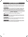
SAFETY INFORMATION
The purpose of safety symbols is to attract our attention to possible dangers. The
safety symbols, and the explanations with them, deserve your careful attention and
understanding. The symbol warnings do not by themselves eliminate any danger.
The instructions and warnings they give are no substitutes for proper accident pre-
vention measures.
Be sure to read and understand all safety instructions in this
manual, including all safety alert symbols, such as “DANGER”, “WARNING” and
“CAUTION” before using this battery charger. Failure to follow all instructions
listed below may result in electric shock, fire and/or serious personal injury.
SYMBOL MEANING
SAFETY ALERT SYMBOL: Indicates DANGER, WARNING or CAUTION.
May be used in conjunction with other symbols or pictographs.
Failure to obey this safety warning WILL result in death or serious
injury to yourself or to others. Always follow the safety precautions to reduce the risk
of fire, electric shock and personal injury.
Failure to obey this safety warning CAN result in death or
serious injury to yourself or to others. Always follow the safety precautions to
reduce the risk of fire, electric shock and personal injury.
Failure to obey this safety warning MAY result in personal
injury to yourself or others, or property damage. Always follow the safety precautions
to reduce the risk of fire, electric shock and personal injury.

Page 5
1. IMPORTANT SAFETY INSTRUCTIONS
1.1
SAVE THESE INSTRUCTIONS – This
manual contains important safety and
operating instructions.
1.2
Do not expose the charger to rain or
snow.
1.3
Use of an attachment not recom-
mended or sold by the battery
charger manufacturer may result in a
risk of fire, electric shock or injury to
persons.
1.4
To reduce the risk of damage to elec-
tric plug and cord, pull by the plug
rather than the cord when discon-
necting charger.
1.5
An extension cord should not be
used unless absolutely necessary.
Use of improper extension cord
could result in a risk of fire and elec-
tric shock. If an extension cord must
be used, make sure:
• The pins on plug of extension cord
are the same number, size and
shape as those of plug on charger.
• The extension cord is properly wired
and in good electrical condition.
• The wire size is large enough for
AC ampere rating of charger as
specified in section 8.
1.6
Do not operate charger with dam-
aged cord or plug – replace the cord
or plug immediately.
1.7
Do not operate charger if it has
received a sharp blow, been dropped,
or otherwise damaged in any way;
take it to a qualified serviceman.
1.8
Do not disassemble charger; take it
to a qualified serviceman when ser-
vice or repair is required. Incorrect
reassembly may result in a risk of
electric shock or fire.
1.9
To reduce risk of electric shock,
unplug charger from outlet before
attempting any maintenance or
cleaning. Turning off controls will not
reduce this risk.
1.10
RISK OF EXPLOSIVE GASES.
a.
WORKING IN VICINITY OF A LEAD-
ACID BATTERY IS DANGEROUS.
BATTERIES GENERATE EXPLO-
SIVE GASES DURING NORMAL
BATTERY OPERATION. FOR
THIS REASON, IT IS OF UTMOST
IMPORTANCE THAT YOU FOL-
LOW THE INSTRUCTIONS EACH
TIME YOU USE THE CHARGER.
b.
To reduce risk of battery explo-
sion, follow these instructions
and those published by battery
manufacturer and manufacturer
of any equipment you intend to
use in vicinity of battery. Review
cautionary markings on these
products and on engine.
1.11
Keep out of reach of children.
2. PERSONAL SAFETY PRECAUTIONS
2.1
Consider having someone close
enough by to come to your aid when
you work near a lead-acid battery.
2.2
Have plenty of fresh water and soap
nearby in case battery acid contacts
skin, clothing, or eyes.
2.3
Wear complete eye protection and
clothing protection. Avoid touching
eyes while working near battery.
2.4
If battery acid contacts skin or cloth-
ing, wash immediately with soap and
water. If acid enters eye, immediately
flood eye with running cold water for
at least 10 minutes and get medical
attention immediately.
2.5
NEVER smoke or allow a spark or
flame in vicinity of battery or engine.
2.6
Be extra cautious, to reduce risk of
dropping a metal tool onto battery.
It might spark or short-circuit bat-
tery or other electrical part that may
cause explosion.
2.7
Remove personal metal items such
as rings, bracelets, necklaces, and
watches when working with a lead-
acid battery. A lead-acid battery can

Page 6
produce a short-circuit current high
enough to weld a ring or the like to
metal, causing a severe burn.
2.8
Use the charger for charging only 6V
and 12V LEAD-ACID (STD, GEL or
AGM) rechargeable batteries. It is not
intended to supply power to a low
voltage electrical system other than in
a starter-motor application. Do not use
battery charger for charging dry-cell
batteries that are commonly used with
home appliances. These batteries may
burst and cause injury to persons and
damage to property.
2.9
NEVER charge a frozen battery.
3. PREPARING TO CHARGE
3.1
If necessary to remove battery from
vehicle to charge, always remove
grounded terminal from battery first.
Make sure all accessories in the vehi-
cle are off, so as not to cause an arc.
3.2
Be sure area around battery is well
ventilated while battery is being
charged.
3.3
Clean battery terminals. Be careful to
keep corrosion from coming in con-
tact with eyes.
3.4
Add distilled water in each cell until
battery acid reaches level specified by
battery manufacturer. Do not overfill.
For a battery without removable cell
caps, such as valve regulated lead
acid batteries, carefully follow manu-
facturer’s recharging instructions.
3.5
Study all battery manufacturer’s spe-
cific precautions while charging and
recommended rates of charge.
3.6
Determine voltage of battery by
referring to car owner’s manual and
make sure that output voltage selec-
tor switch is set at correct voltage. If
charger has adjustable charge rate,
charge battery initially at lowest rate.
4. CHARGER LOCATION
4.1
Locate charger as far away from bat-
tery as DC cables permit.
4.2
Never place charger directly above
battery being charged; gases from
battery will corrode and damage
charger.
4.3
Never allow battery acid to drip on
charger when reading electrolyte
specific gravity or filling battery.
4.4
Do not operate charger in a closed-in
area or restrict ventilation in any way.
4.5
Do not set a battery on top of charger.
5. DC CONNECTION PRECAUTIONS
5.1
Connect and disconnect DC output
clips only after setting any charger
switches to “off” position and remov-
ing AC cord from electric outlet. Never
allow clips to touch each other.
5.2
Attach clips to battery and chassis,
as indicated in sections 6 and 7.
6. FOLLOW THESE STEPS WHEN BATTERY IS INSTALLED IN VEHICLE
A SPARK NEAR THE BATTERY MAY
CAUSE A BATTERY EXPLOSION. TO
REDUCE THE RISK OF A SPARK NEAR
THE BATTERY:
6.1
Position AC and DC cords to reduce
risk of damage by hood, door, or mov-
ing engine part.
6.2
Stay clear of fan blades, belts, pulleys,
and other parts that can cause injury
to persons.

Page 7
6.3
Check polarity of battery posts. POS-
ITIVE (POS, P, +) battery post usually
has larger diameter than NEGATIVE
(NEG, N,–) post.
6.4
Determine which post of battery is
grounded (connected) to the chas-
sis. If negative post is grounded to
chassis (as in most vehicles), see
(6.5). If positive post is grounded to
the chassis, see (6.6).
6.5
For negative-grounded vehicle, con-
nect POSITIVE (RED) clip from battery
charger to POSITIVE (POS, P, +)
ungrounded post of battery. Connect
NEGATIVE (BLACK) clip to vehicle
chassis or engine block away from
battery. Do not connect clip to carbu-
retor, fuel lines, or sheet-metal body
parts. Connect to a heavy gauge metal
part of the frame or engine block.
6.6
For positive-grounded vehicle, con-
nect NEGATIVE (BLACK) clip from
battery charger to NEGATIVE (NEG,
N, –) ungrounded post of battery.
Connect POSITIVE (RED) clip to
vehicle chassis or engine block away
from battery. Do not connect clip to
carburetor, fuel lines, or sheet-metal
body parts. Connect to a heavy
gauge metal part of the frame or
engine block.
6.7
When disconnecting charger, turn
switches to off, disconnect AC cord,
remove clip from vehicle chassis,
and then remove clip from battery
terminal.
6.8
See Operating Instructions for length
of charge information.
7. FOLLOW THESE STEPS WHEN BATTERY IS OUTSIDE VEHICLE
A SPARK NEAR THE BATTERY MAY
CAUSE A BATTERY EXPLOSION. TO
REDUCE THE RISK OF A SPARK NEAR
THE BATTERY:
7.1
Check polarity of battery posts. POS-
ITIVE (POS, P, +) battery post usually
has a larger diameter than NEGATIVE
(NEG, N, –) post.
7.2
Attach at least a 24-inch-long 6-gauge
(AWG) insulated battery cable to
NEGATIVE (NEG, N, –) battery post.
7.3
Connect POSITIVE (RED) charger
clip to POSITIVE (POS, P, +) post of
battery.
7.4
Position yourself and free end of
cable as far away from battery as
possible – then connect NEGATIVE
(BLACK) charger clip to free end of
cable.
7.5
Do not face battery when making
final connection.
7.6
When disconnecting charger, always
do so in reverse sequence of con-
necting procedure and break first
connection while as far away from
battery as practical.
7.7
A marine (boat) battery must be
removed and charged on shore. To
charge it on board requires equipment
specially designed for marine use.
8. GROUNDING AND AC POWER CORD CONNECTIONS
8.1
This battery charger is for use on a
nominal 120 volt circuit and has a
grounded plug. The charger must be
grounded, to reduce the risk of electric
shock. The plug must be plugged into
an outlet that is properly installed and
grounded in accordance with all local
codes and ordinances. The plug pins
must fit the receptacle (outlet). Do not
use with an ungrounded system.
8.2
Never alter the AC
cord or plug provided – if it does not
fit the outlet, have a proper grounded
outlet installed by a qualified elec-
trician. An improper connection can
result in a risk of an electric shock or
electrocution.
NOTE: Pursuant to Canadian Regu-
lations, use of an adapter plug is not
allowed in Canada. Use of an adapter
plug in the United States is not rec-
ommended and should not be used.

Page 8
8.3
USING AN EXTENSION CORD
The use of an extension cord is not
recommended. If you must use an
extension cord, follow these guidelines:
• Pins on plug of extension cord must
be the same number, size, and
shape as those of plug on charger.
• Ensure that the extension cord is
properly wired and in good electri-
cal condition.
• Wire size must be large enough for
the AC ampere rating of charger,
as specified:
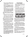
Length of cord (feet) 25 50 100 150
AWG* size of cord 18 16 14 14
*AWG-American Wire Gauge
9. ASSEMBLY INSTRUCTIONS
9.1
Remove all cord wraps and uncoil the
cables prior to using the battery charger.
10. CONTROL PANEL
DIGITAL DISPLAY
The digital display indicates the status of
the battery and charger. See the Display
Messages section for a complete list of
messages.
NOTE: During charging, the display will
go into sleep mode and will not show the
percentage of charge or voltage of the
battery. To turn the display back on, press
the Display button.
DISPLAY MODE BUTTON
Use this button to set the function of the
digital display to one of the following:
• Battery % – The digital display shows
an estimated charge percentage of the
battery connected to the charger’s bat-
tery clamps.
• Alternator % – The digital display shows
an estimated output percentage of the
vehicle’s charging system connected
to the charger’s battery clamps, com-
pared to a properly functioning system.
The alternator percent range is from 0
to 100%. Readings below 0 (13.2 volts)
will read LOW and readings above 100%
(14.6 volts) will read HIGH. If you get a
HIGH or LOW reading, have the electrical
system checked by a qualified techni-
cian.
• Voltage – The Digital Display shows the
voltage at the charger battery clamps,
in DC volts, prior to charging. During
charging, it shows the auto-detected
battery charge voltage.
RATE SELECTION BUTTON
Use this button to select one of the following:
• 6A<>2A CHARGE/MAINTAIN – For
charging small and large batteries. Not
recommended for industrial applications.
• 40<>15A BOOST – For quickly adding
energy to a severely discharged or large
capacity battery prior to Engine Start. The
battery voltage will be regulated at 13.6V.
• 125A ENGINE START – Provides addi-
tional amps for cranking an engine with a
weak or run-down battery. Always use in
combination with a battery.
NOTE: Once the charger has started
charging the battery, if you press the Rate
Selection button once, the output current
is shut off and the display with show OFF
and then the battery voltage. If you press
the Rate Selection button again, the cur-
rent will go back on at the same setting it
was when it was turned off.
LED INDICATORS
CLAMPS REVERSED (red) LED flashing:
The connections are reversed.
CHARGING (yellow/orange) LED lit: The
charger is charging the battery.
CHARGED/MAINTAINING (green) LED lit:
The battery is fully charged and the char-
ger is in maintain mode.
NOTE: See the Operating Instructions
section for a complete description of the
charger modes.

Page 9
BATTERY TYPE BUTTON
Use this button to set the type of battery.
NOTE: Each of the three settings apply for
regular and deep-cycle batteries.
• STANDARD – Used in cars, trucks and
motorcycles, these batteries have vent
caps and are often marked “low main-
tenance” or “maintenance-free”. This
type of battery is designed to deliver
quick bursts of energy (such as starting
engines) and has a greater plate count.
The plates are thinner and have some-
what different material composition.
• AGM – The Absorbed Glass Mat con-
struction allows the electrolyte to be
suspended in close proximity with
the plate’s active material. In theory,
this enhances both the discharge and
recharge efficiency. The AGM batter-
ies are a variant of Sealed VRLA (valve
regulated lead-acid) batteries. Popular
uses include high-performance engine
starting, power sports, deep-cycle,
solar and storage batteries.
• GEL – The electrolyte in a GEL cell has
a silica additive that causes it to set
up or stiffen. The recharge voltages on
this type of cell are lower than those for
other styles of lead-acid battery. This is
probably the most sensitive cell in terms
of adverse reactions to overvoltage
charging. Gel batteries are best used in
VERY DEEP cycle application and may
last a bit longer in hot weather appli-
cations. If the wrong battery charger is
used on a gel cell battery, poor perfor-
mance and premature failure will result.
11. OPERATING INSTRUCTIONS
A SPARK NEAR BATTERY MAY CAUSE
AN EXPLOSION.
IMPORTANT: Do not start the vehicle with
the charger connected to the AC outlet,
or it could damage the charger.
NOTE: This charger is equipped with an
auto-start feature. Current will not be sup-
plied to the battery clamps until a battery
is properly connected. The clamps will not
spark if touched together.
CHARGING A BATTERY
IN THE VEHICLE
1.
Turn off all the vehicle’s accessories.
2.
Keep the hood open.
3.
Clean the battery terminals.
4.
Place the charger on a dry, non-flam-
mable surface.
5.
Lay the AC/DC cables away from any
fan blades, belts, pulleys and other
moving parts.
6.
Connect the battery, following the pre-
cautions listed in sections 6 and 7.
7.
Connect the charger to an electrical
outlet.
8.
Select the battery type and the desired
rate. Charging will then begin automat-
ically. See section 12 for CHARGING
message details.
9.
The yellow/orange LED will light, and the
display will show ANALYZING BATTERY
while the charger determines that the
battery is properly connected and the
condition of the battery.
NOTE: It will
take 10 minutes to detect a 6V battery.
10.
When charging is complete, disconnect
the charger from the AC power, remove
the clamps from the vehicle’s chassis,
and then remove the clamp from the
battery terminal.
CHARGING A BATTERY
OUTSIDE OF THE VEHICLE
1.
Place battery in a well-ventilated area.
2.
Clean the battery terminals.
3.
Connect the battery, following the pre-
cautions listed in sections 6 and 7.
4.
Connect the charger to the electrical
outlet.
5.
Select the battery type and the desired
rate. Charging will then begin automat-
ically. See section 12 for CHARGING
message details.
6.
The yellow/orange LED will light, and the
display will show ANALYZING BATTERY
while the charger determines that the
battery is properly connected and the
condition of the battery.
NOTE: It will
take 10 minutes to detect a 6V battery.
7.
When charging is complete, discon-
nect the charger from the AC power,
disconnect the negative clamp, and
finally the positive clamp.
8.
A marine (boat) battery must be removed
and charged on shore.

Page 10
AUTOMATIC CHARGING MODE
When an Automatic Charge is performed,
the charger switches to the maintain mode
automatically after the battery is charged.
BATTERY CONNECTION INDICATOR
If the charger does not detect a properly
connected battery, charging will not start
and the digital display will show one of two
messages. If the display shows CONNECT
CLAMPS, make sure the charger is con-
nected to the battery and the connection
points are clean and making a good con-
nection. If the display shows WARNING
CLAMPS REVERSED, unplug the charger
from the AC outlet and reverse the connec-
tions at the battery.
BATTERY CHARGING TIMES
APPLICATION
BATTERY
SIZE
CHARGING TIME (Hours)
2A 6A 8A 10A
POWERSPORTS
6Ah 6
32 Ah 15
AUTOMOTIVE
300 CCA 12
1000 CCA 30
MARINE
50 Ah 15
105Ah 33
2
5
4
10
5
11
1.75
4.5
3.5
8.5
4.25
9.5
1.5
4
3
7
3.5
8
Times are based on a 50% discharged battery
and may change, depending on age and condi-
tion of battery.
CHARGE COMPLETION
AND MAINTAIN MODE
(FLOAT MODE MONITORING)
Charge completion is indicated by the solid
green LED and the digital display showing
FULLY CHARGED AUTO MAINTAINING.
This means that the charger has stopped
charging and has switched to the Maintain
Mode of operation. NOTE: If the charger
has to provide its maximum maintain cur-
rent for a continuous 12 hour period, it will
go into Abort Mode (see Aborted Charge
section). This is usually caused by a drain
on the battery, or the battery could be
bad. Make sure there are no loads on the
battery. If there are, remove them. If there
are none, have the battery checked or
replaced.
MAINTAINING A BATTERY
The 260-9513 maintains 6 and 12 volt bat-
teries, keeping them at full charge. It is not
recommended for industrial applications.
NOTE: The maintain mode technology
allows you to safely charge and maintain
a healthy battery for extended periods of
time. However, problems with the bat-
tery, electrical problems in the vehicle,
improper connections or other unantici-
pated conditions could cause excessive
current draws. As such, occasionally
monitoring your battery and the charging
process is required.
DESULFATION MODE
If the battery is left discharged for an
extended period of time, it could become
sulfated and not accept a normal charge.
If the charger detects a sulfated battery,
the charger will switch to a special mode
of operation designed for such batteries.
If successful, normal charging will resume
after the battery is desulfated. Desulfation
could take up to 10 hours. If desulfation
fails, charging will abort and the display
will show CHARGING ABORTED BAD
BATTERY.
ABORTED CHARGE
If charging cannot be completed nor-
mally, charging will abort. When charging
aborts, the charger’s output is shut off
and the display will show CHARGING
ABORTED BAD BATTERY. To reset after
an aborted charge, unplug the charger
from the outlet, wait a few moments and
plug it back in.
USING THE ENGINE START SETTING
Your battery charger can be used to jump
start your car if the battery is low. Follow
all safety instructions and precautions for
charging your battery. Wear complete eye
protection and protective clothing.
Using the Engine Start
setting WITHOUT a battery installed in the
vehicle could cause damage to the vehicle’s
electrical system.
NOTE: If you have charged the battery
and it still will not start your car, do not
use the Engine Start setting, or it could
damage the vehicle’s electrical system.
Have the battery checked.

Page 11
1.
With the charger unplugged from the
AC outlet, connect the charger to the
battery, following the instructions given
in sections 6 and 7.
2.
With the charger plugged in and con-
nected to the battery and chassis,
press the Rate Selection button until
the Engine Start LED is lit. The display
will show ENGINE START ON after 2
seconds.
3.
When the display shows ENGINE
START READY, crank the engine until it
starts or 3 seconds pass. If the engine
does not start, wait 3 minutes (until the
display shows ENGINE START READY)
before cranking again. This allows the
charger and battery to cool down.
NOTE: During extremely cold weather,
or if the battery is under 2 volts, charge the
battery for 5 minutes before cranking the
engine.
4.
If the engine fails to start, charge the
battery for 5 more minutes before
attempting to crank the engine again.
5.
After the engine starts, unplug the AC
power cord before disconnecting the
battery clamps from the vehicle.
NOTE: If the engine does turn over but
never starts, there is not a problem with
the starting system; there is a problem
somewhere else with the vehicle. STOP
cranking the engine until the other prob-
lem has been diagnosed and corrected.
ENGINE STARTING NOTES
During the starting sequence, the charger
is set to one of three states:
• Wait for cranking – The charger waits
until the engine is actually being cranked
before delivering the amps for engine
start. After 5 seconds, the display will
change to ENGINE START READY.
• Cranking – When cranking is detected,
the charger will automatically deliver up
to its maximum output as required by
the starting system for up to 5 seconds
or until the engine cranking stops. The
digital display shows a countdown of the
remaining crank time.
• Cool Down – After cranking, the charger
enters a mandatory 3 minute (180 sec-
ond) cool down state. The digital display
will show ENGINE START COOL DOWN
XXX SECONDS REMAINING. It starts at
180 and counts down to 0. After 3 min-
utes, the digital display will change to
ENGINE START READY.
USING THE BATTERY
VOLTAGE TESTER
1.
With the charger unplugged from the
AC outlet, connect the charger to the
battery, following the instructions given
in previous sections.
2.
Plug the charger’s AC power cord into
the AC outlet.
3.
Set the ON/OFF switch to Boost/
Charge/Maintain. DO NOT choose a
rate with the Rate Selection button.
4.
If necessary, press the Battery Type but-
ton until the correct type is indicated.
5.
Read the voltage on the digital display.
Keep in mind that this reading is only a
battery voltage reading; a false surface
charge may mislead you. Compare the
reading to the following chart.
6V Battery
Voltage
Reading
12V Battery
Voltage
Reading
Battery
Condition
6.4 or more 12.8 or more Charged
6.1 to 6.3 12.2 to 12.7
Needs
charging
Less than 6.1 Less than 12.2 Discharged
TESTER AND CHARGER
When first turned on, the unit operates
only as a tester, not as a charger. Selecting
a charge rate activates the battery charger
and deactivates the tester. Pressing the
Rate Selection button when the Engine
Start LED is lit (except during the 180 sec-
ond cool down) will shut off the charger
and activate the tester.
POWER-UP IDLE TIME LIMIT
If no button is pressed within 30 seconds
after the battery charger is first powered
up, the charger will automatically switch
from tester to Boost mode if a battery is
connected. In that case, the charger will
be set to the 40A<>15A Boost rate and
AGM battery type.
TESTING AFTER CHARGING
After the unit has been changed from
tester to charger (by selecting a charge
rate), it remains a charger. To change the
battery charger back to a tester, press the
Rate Selection button until all charge rate
LEDs are off.
NOTE: The battery tester is only designed
to test batteries. Testing a device with a
rapidly changing voltage could yield unex-
pected or inaccurate results.

Page 12
USING THE ALTERNATOR
PERFORMANCE TESTER
1.
With the charger unplugged from the
AC outlet, connect the charger to the
battery, following the instructions given
in previous sections.
2.
Plug the charger AC power cord into
the AC outlet.
3.
Start the vehicle, rev the engine at 2000
rpm for 30 seconds and turn on the vehi-
cle’s headlights or other accessories.
4.
Read the voltage on the digital display.
If you get a reading between 13.4 volts
and 14.6 volts, the alternator is working
properly. If the reading is less than 13.4
volts or more than 14.6 volts, have the
charging system checked by a qualified
technician.
NOTE: Refer to your vehicle owner’s man-
ual for appropriate voltage numbers for
your alternator.
FAN OPERATION
It is normal for the fan to start and stop
when maintaining a fully charged bat-
tery. The fan does not run in Tester Mode.
Keep the area near the charger clear of
obstructions, to allow the fan to operate
efficiently.
RESTART
If the Charge Mode is changed after
charging has started (by pressing the
Rate Selection or Battery Type button), the
charging process will restart.
12. DISPLAY MESSAGES
CONNECT CLAMPS (VOLTAGE LED lit) –
Plugged into the AC outlet without the
clamps connected to a 6 or 12V battery.
WARNING CLAMPS REVERSED (Red
REVERSED LED flashing) – Plugged into
the AC outlet and the clamps are con-
nected backwards to a battery. Scrolls
until condition is corrected.
ANALYZING BATTERY (Yellow/orange
CHARGING LED lit) – Plugged into the
AC outlet, connected to a 6 or 12V bat-
tery correctly and a charge rate has been
selected. NOTE: It will take 10 minutes to
detect a 6V battery.
CHARGING 6V – XX% (Yellow/orange
CHARGING LED lit) – Plugged into the AC
outlet and correctly connected to a dis-
charged 6V battery.
CHARGING 12V – XX% (Yellow/orange
CHARGING LED lit) – Plugged into the AC
outlet and correctly connected to a dis-
charged 12V battery.
FULLY CHARGED AUTO MAINTAINING
(Green CHARGED/MAINTAINING LED
solid) – Plugged into the AC outlet and
correctly connected to a fully charged 6V
or 12V battery.
CHARGING ABORTED BAD BATTERY
(Yellow/orange CHARGING LED flashing) –
Circumstances that could cause an Abort
situation during charging:
• The battery is severely sulfated or has a
shorted cell and can’t reach a full charge.
• The battery is too large or there is a
bank of batteries and it doesn’t reach
full charge within a set time period.
Circumstances that could cause an Abort
situation during maintaining:
• The battery is severely sulfated or has
a weak cell and will not hold a charge.
• There is a large draw on the battery and
the charger has to supply its maximum
maintain current for a 12 hour period to
keep the battery at full charge.
ENGINE START ON (Battery Type LED lit) –
The Engine Start rate has been selected; the
charger is not yet ready for engine start.
ENGINE START READY (Battery Type LED
lit) – The charger is ready for engine start.
ENGINE START COOL DOWN XXX
SECONDS REMAINING (Battery Type LED lit)–
The charger is in a mandatory 3 minute (180
second) cool down state.
BATTERY DISCONNECTED – Charging is
complete and clamps have been discon-
nected.

Page 13
13. MAINTENANCE AND CARE
A minimal amount of care can keep your
battery charger working properly for years.
• Clean the clamps each time you are
finished charging. Wipe off any battery
fluid that may have come in contact
with the clamps to prevent corrosion.
• Occasionally cleaning the case of the
charger with a soft cloth will keep the
finish shiny and help prevent corrosion.
• Coil the input and output cords neatly
when storing the charger. This will help
prevent accidental damage to the cords
and charger.
• Store the charger unplugged from the
AC power outlet in an upright position.
• Store the clamps on the storage areas
provided on the handle. Do not store
the clamps clipped together, on or
around metal, or clipped to the cables.
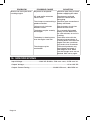
14. TROUBLESHOOTING
PROBLEM POSSIBLE CAUSE SOLUTION
The charger will not turn on
when properly connected.
AC outlet is dead.
Poor electrical connection.
Battery is defective.
Check for open fuse or circuit
breaker supplying AC outlet.
Check power cord and
extension cord for loose
fitting plug.
Have battery checked.
The battery is connected and
the charger is on, but is not
charging.
The charger is in tester
mode, not charge mode.
Press the Rate Selection
button to activate the charge
mode and select a charge
rate.
No reading on the digital
display.
Charger is not plugged in.
No power at the receptacle.
The display is in sleep mode,
during charging.
Plug the charger into an AC
outlet.
Check for open fuse or circuit
breaker supplying AC outlet.
Press the Display button to
turn the display back on.
Digital Display reads LOW
when testing the alternator.
The alternator output is 13.2
volts or less.
Have the electrical system
checked by a qualified
technician.
Digital Display reads HIGH
when testing the alternator.
The alternator output is 14.6
volts or more.
Have the electrical system
checked by a qualified
technician.
Yellow/orange Charging
LED is solid and the
display shows ANALYZING
BATTERY.
The charger needs to check
the condition of the battery.
The charger has not
completed the checking
process. This process can
last for up to 10 minutes.
The display shows CHARGE
ABORTED BAD BATTERY.
The battery is sulfated.
The battery is too large for
the charger.
Reset the charger by briefly
unplugging it.
You need a charger with a
higher amp rate.
The display shows
CONNECT CLAMPS.
The clamps are not making a
good connection.
Check for poor connection at
battery and frame.

Page 14
PROBLEM POSSIBLE CAUSE SOLUTION
Short or no start cycle when
cranking engine.
No power at receptacle.
AC cord and/or extension
cord is loose.
The clamps are not making a
good connection.
Failure to wait 3 minutes
between cranks.
The battery may be severely
discharged.
The battery is drawing more
than the engine start rate.
The charger may be
overheated.
Check for open fuse or circuit
breaker supplying AC outlet.
Check power cord and
extension cord for loose
fitting plug.
Check for poor connection at
battery and frame.
Wait 3 minutes of rest time
before the next crank.
On a severely discharged
battery, use the Boost rate
for a few minutes, to assist in
cranking.
Crank time varies with the
amount of current drawn. If
cranking draws more than the
engine start rate, crank time
may be less than 5 seconds.
The thermal protector may
have tripped and needs a
little longer to reset. Make
sure the charger vents are not
blocked. Wait and try again.
15. SPECIFICATIONS
Input Voltage ...................................120V AC @ 60Hz, 5.2A max cont.; 21.5A max int.
Output Voltage ......................................................................................... 6V or 12V DC
Output Current Rating ................................................ 2A/6A/15A cont., 40A/125A int.

125A Automatic Battery Charger & Engine Starter
WARRANTY
90-DAY MONEY BACK GUARANTEE
This MASTERFORCE™ brand battery charger carries our 90-Day Money Back
Guarantee. If you are not completely satisfied with your MASTERFORCE™
brand product for any reason within ninety (90) days from the date of purchase,
return the item with your original receipt to any MENARDS
®
retail store, and we
will provide you a refund – no questions asked.
3-YEAR LIMITED WARRANTY
This MASTERFORCE™ brand battery charger carries our famous No Hassle
3-Year Limited Warranty to the original purchaser. If, during normal use, this MAS-
TERFORCE™ product breaks or fails due to a defect in material or workmanship
within three (3) years from the date of original purchase, simply bring the item
with the original sales receipt back to your nearest MENARDS
®
retail store. At its
discretion, MASTERFORCE™ agrees to have the item or any defective part(s)
repaired or replaced with the same or similar MASTERFORCE™ product or part
free of charge, within the stated warranty period, when returned by the original
purchaser with original sales receipt. Not withstanding the foregoing, this limited
warranty does not cover any damage that has resulted from abuse or misuse of
the Merchandise. This warranty: (1) excludes expendable parts including but not
limited to blades, brushes, belts, bits, light bulbs, and/or batteries; (2) shall be
void if this product is used for commercial and/or rental purposes; and (3) does
not cover any losses, injuries to persons/property or costs. This warranty does
give you specific legal rights and you may have other rights, which vary from
state to state. Be careful, battery chargers are dangerous if improperly used or
maintained. Seller’s employees are not qualified to advise you on the use of this
merchandise. Any oral representation(s) made will not be binding on seller or its
employees. The rights under this limited warranty are to the original purchaser
of the merchandise and may not be transferred to any subsequent owner. This
limited warranty is in lieu of all warranties, expressed or implied including war-
ranties or merchantability and fitness for a particular purpose. Seller shall not be
liable for any special, incidental, or consequential damages. The sole exclusive
remedy against the seller will be for the replacement of any defects as provided
herein, as long as the seller is willing or able to replace this product or is willing
to refund the purchase price as provided above. For insurance purposes, seller
is not allowed to demonstrate any of these products for you.
For questions/comments, technical assistance or repair parts—
Please call toll free at: 1-800-621-5485.
Page 15
1. WARRANTY

© 2020 Menard, Inc., Eau Claire, WI 54703
10/2020
-
 1
1
-
 2
2
-
 3
3
-
 4
4
-
 5
5
-
 6
6
-
 7
7
-
 8
8
-
 9
9
-
 10
10
-
 11
11
-
 12
12
-
 13
13
-
 14
14
-
 15
15
-
 16
16


Schumacher 260-9513 125A Automatic Battery Charger/Engine Starter MF187 Owner's manual
- Category
- Car battery chargers
- Type
- Owner's manual
Ask a question and I''ll find the answer in the document
Finding information in a document is now easier with AI
Related papers
-
Schumacher Masterforce 260-9514 275A Automatic Battery Charger & Engine Starter MF186 Owner's manual
-
-
-
-
-
-
Schumacher DSR121 Professional Wheel Charger DSR122 Professional Wheel Charger DSR123 Professional Wheel Charger DSR124 Professional Wheel Charger Owner's manual
-
-
-
Other documents
-
DieHard 71345 Owner's manual
-
-
-
-
 pro.point Battery Charger User manual
-
-
Schumacher Electric SCF-8020A Owner's manual
-
-
Schumacher Electric SE-2151MA Owner's manual
-
Associated 3055A Owner's manual
