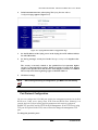
IMC Networks AccessLinX User manual
- Category
- Networking
- Type
- User manual

52-80420-00 A0
AccessLinX
VoIP GATEWAY
H.323, MGCP, SIP
USER GUIDE

52-80420-00 A0
ii
Contents
1 OVERVIEW .................................................................................................................................. 1-1
1.1 PRODUCT OVERVIEW ............................................................................................................. 1-1
1.2 F
EATURES
............................................................................................................................... 1-1
1.3 LASER SAFETY .......................................................................................................................1-3
1.4 HOW TO GET HELP.................................................................................................................1-3
2
PRE-INSTALLATION REQUIREMENTS ..............................................................................2-1
2.1 S
UPPORTING
E
QUIPMENT
R
EQUIREMENTS
............................................................................ 2-1
2.2 TELEPHONES AND ACCESSORIES ...........................................................................................2-1
3
GATEWAY INSTALLATION.................................................................................................... 3-1
3.1 I
NSTALLING THE
V
O
IP G
ATEWAY
......................................................................................... 3-1
4 GATEWAY INITIAL CONFIGURATION AND BACKGROUND INFORMATION ...... 4-1
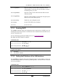
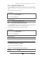
4.1 KEYPAD CONFIGURATION......................................................................................................4-1
4.1.1
Keypad Configuration for MGCP.................................................................................... 4-2
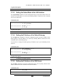
4.2 UNDERSTANDING DHCP .......................................................................................................4-2
4.2.1 When Should Clients Use DHCP .....................................................................................4-4
4.3
UNDERSTANDING NAT AND NAPT ...................................................................................... 4-4
4.4 UNDERSTANDING NTP...........................................................................................................4-4
4.4.1 Daylight Saving Time (Summer Time) .............................................................................4-5
4.5
UNDERSTANDING SYSLOG .....................................................................................................4-5
4.5.1 Remote Logging................................................................................................................4-6
4.6 DIAL PLAN FOR SIP AND H.323.............................................................................................4-7
4.6.1
Default Dial Plan ............................................................................................................. 4-7
4.6.2 Dial Plan Syntax...............................................................................................................4-7
4.6.3 Dial Plan Examples..........................................................................................................4-8
4.7
DNS RESOLVER ...................................................................................................................4-10
5 USING THE VOIP GATEWAY ................................................................................................. 5-1
5.1 FIRST CALL ............................................................................................................................5-1
5.2 P
LACING
C
ALLS
.....................................................................................................................5-1
5.3 ADDING ADDITIONAL UNITS .................................................................................................5-2
5.4 ADVANCED CALLING FEATURES FOR SIP..............................................................................5-2
5.4.1 Call Waiting......................................................................................................................5-2
5.4.2 Conference Call................................................................................................................5-2
5.4.3
Forwarding a Call............................................................................................................ 5-2
5.4.4 Attended Transfer Call .....................................................................................................5-2
5.4.5 Blind Transfer Call...........................................................................................................5-3
5.4.6
Hold ..................................................................................................................................5-3
5.4.7 Conditional Call Forwarding ..........................................................................................5-3
5.4.8 Do Not Disturb (DND).....................................................................................................5-3
5.4.9
Redialing to Last Received Caller ................................................................................... 5-3
5.4.10 Block Last Received Caller ......................................................................................... 5-3
5.4.11 Auto Redial ..................................................................................................................5-3
5.5
ADVANCED CALLING FEATURES FOR H.323.......................................................................... 5-4
5.5.1 Call Waiting......................................................................................................................5-4
5.5.2 Conference Call................................................................................................................5-4
5.5.3
Forwarding a Call............................................................................................................ 5-4
5.5.4 Transferring a Call...........................................................................................................5-5
5.5.5 Hold ..................................................................................................................................5-5
5.6
ADVANCED CALLING FEATURES FOR MGCP........................................................................ 5-5

52-80420-00 A0
iii
6
UPGRADING THE GATEWAY FIRMWARE AND DOWNLOADING
CONFIGURATION FILES................................................................................................................... 6-1
6.1 DOWNLOADING THE FILE MANUALLY USING TELNET ..........................................................6-2
6.2 DOWNLOADING THE FILE MANUALLY USING THE WEB ........................................................6-3
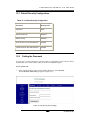
6.3 DHCP A
UTOMATIC
C
ONFIGURATION
...................................................................................6-3
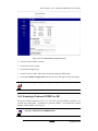
6.3.1 Setting DHCP Automatic Configuration via the Web .....................................................6-3
6.3.2 Setting DHCP Automatic Configuration via Telnet ........................................................6-6
6.4 F
IXED
(P
ROVISIONED
) HTTP
OR
TFTP A
UTOMATIC
C
ONFIGURATION
................................6-7
6.4.1 Setting the TFTP/HTTP Server “Root” Configuration File via the Web .......................6-7
6.4.2 Setting the TFTP Server “Root” Configuration File via Telnet .....................................6-8
6.5 C
REATING AND
E
NCRYPTING
C
ONFIGURATION
F
ILES
...........................................................6-9
7 CONFIGURING THE GATEWAY VIA TELNET .................................................................7-1
7.1 STARTING A TELNET SESSION................................................................................................ 7-1
7.2
COMMAND MODES.................................................................................................................7-3
7.2.1 Enable Mode.....................................................................................................................7-3
7.2.2 Commands Mode ..............................................................................................................7-3
7.2.3
Report Mode .....................................................................................................................7-3
7.2.4 Statistics Mode.................................................................................................................. 7-4
7.2.5 Download Mode ...............................................................................................................7-4
7.2.6
Configuration Modes........................................................................................................ 7-5
7.3 GENERAL COMMANDS ...........................................................................................................7-7
7.4 USING THE CLI COMMANDS..................................................................................................7-8
8
CONFIGURING THE GATEWAY VIA A TERMINAL........................................................8-1
9
CONFIGURING THE GATEWAY VIA THE WEB...............................................................9-1
9.1 CONFIGURING THE GATEWAY’S IP ADDRESS AND DNS SETTINGS ......................................9-1
9.1.1 Setting the Gateway to be a DHCP Client.......................................................................9-4
9.1.2
Using the Gateway with a Fixed Address ........................................................................9-4
9.2 VOIP PROTOCOL CONFIGURATION........................................................................................9-4
9.3 AUTOCONFIGURATION ...........................................................................................................9-4
9.4
CONFIGURING VLANS........................................................................................................... 9-6
9.4.1 Using VLANs on the Gateway..........................................................................................9-7
9.4.2 VLAN Tagging on the Gateway........................................................................................9-7
9.4.3
VLAN Configuration Procedure on the Gateway............................................................9-7
9.5 CONFIGURING VOICE AND MANAGEMENT SERVICES............................................................ 9-9
9.6 SNMP CONFIGURATION ......................................................................................................9-11
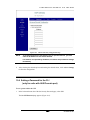
10
CONFIGURING SECURITY VIA THE WEB.......................................................................10-1
10.1 D
EFAULT
S
ECURITY
C
ONFIGURATION
.................................................................................10-2
10.2 SETTING THE PASSWORD .....................................................................................................10-2
10.3
CONFIGURING ADVANCED SECURITY..................................................................................10-3
10.4 S
ETTING A
P
ASSWORD FOR THE
CLI (
ONLY FOR UNITS WITH
AUX/C
ONSOLE PORT
)........ 10-4
10.5 ENABLING/DISABLING CONFIGURATION VIA TELNET .........................................................10-5
10.6
INSTALLING AN ENCRYPTION KEY ......................................................................................10-6
10.7 I
NSTALLING A
G
ENERAL
C
ONFIGURATION
F
ILE
E
NCRYPTION
K
EY
....................................10-7
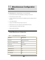
11 MISCELLANEOUS CONFIGURATION VIA WEB ............................................................ 11-1
DEFAULT MISCELLANEOUS CONFIGURATION ....................................................................................11-1
C
LOCK
L
OCALIZATION
.......................................................................................................................11-5
CALLER ID..........................................................................................................................................11-6
SYSLOG SERVER CONFIGURATION .....................................................................................................11-6
P
ORT
P
ROTOCOL
C
ONFIGURATION
.....................................................................................................11-7
SIP ADVANCED CALLING FEATURES AND KEY SEQUENCE CONFIGURATION...................................11-9
RING TONES CONFIGURATION..........................................................................................................11-12
12
PROTOCOL H.323 CONFIGURATION VIA THE WEB....................................................12-1
12.1 DEFAULT H.323 CONFIGURATION .......................................................................................12-1

52-80420-00 A0
iv
12.2 SETTING THE H.323 CONFIGURATION .................................................................................12-2
12.3 DTMF S
IGNALING
...............................................................................................................12-3
12.4 AUDIO/CODEC CONFIGURATION ....................................................................................... 12-5
13 PROTOCOL MGCP CONFIGURATION VIA WEB ...........................................................13-1
13.1
DEFAULT MGCP CONFIGURATION .....................................................................................13-1
13.2 S
ETTING THE
MGCP C
ONFIGURATION
................................................................................13-2
13.3 RTP TELEPHONE EVENT (RFC2833) CONFIGURATION ......................................................13-4
13.4
AUDIO/CODEC CONFIGURATION ....................................................................................... 13-5
14 PROTOCOL SIP CONFIGURATION VIA WEB .................................................................14-1
14.1 DEFAULT SIP CONFIGURATION ...........................................................................................14-1
14.2
SIP SERVER CONFIGURATION ..............................................................................................14-2
14.3 SIP E
XTENSIONS
..................................................................................................................14-6
14.4 LINE-1 AND LINE-2 STATUS AND CONFIGURATION ............................................................14-8
14.5 AUDIO/CODEC CONFIGURATION .....................................................................................14-11
14.6 S
ELECTING A
P
REFERRED
CODEC
FOR
SIP......................................................................14-12
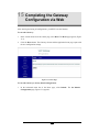
15 COMPLETING THE GATEWAY CONFIGURATION VIA WEB ................................... 15-1
16 SNMP MANAGEMENT OVERVIEW....................................................................................16-2
16.1
NETWORK MANAGEMENT STATION SETUP .........................................................................16-2
17 NETWORK CONFIGURATION VIA TELNET ...................................................................17-1
17.1 DEFAULT LAN CONFIGURATION.........................................................................................17-1
17.2 NETWORK CONFIGURATION COMMANDS ............................................................................17-2
17.2.1 Enabling DHCP.........................................................................................................17-3
17.2.2 Setting the IP Address of the LAN Interfaces............................................................17-3
17.2.3 Setting the Subnet Mask of the LAN Interface ..........................................................17-4
17.2.4 Setting the IP Address of the Default Gateway.........................................................17-4
17.2.5 Setting the IP Address of the DNS Server.................................................................17-4
17.2.6 Setting the Automatic Configuration ID ...................................................................17-5
17.2.7 Enabling the Use of DHCP Options 66, 67 ..............................................................17-5
17.2.8 Enabling the Auto Config Mode................................................................................17-6
17.2.9 Setting the TFTP/HTTP Server IP Address ..............................................................17-6
17.2.10 Setting the File Name ................................................................................................17-7
17.3 LAN DISPLAYING COMMANDS ...........................................................................................17-7
17.3.1 Displaying all the LAN Configuration ......................................................................17-8
17.3.2 Displaying the IP Address of the LAN Interface.......................................................17-8
17.3.3 Displaying the Subnet Mask of the LAN Interface....................................................17-9
18
SECURITY CONFIGURATION VIA TELNET....................................................................18-1
18.1
DEFAULT SECURITY CONFIGURATION.................................................................................18-1
18.2 SECURITY CONFIGURATION COMMANDS.............................................................................18-1
18.2.1 Entering into LAN Configuration Mode ...................................................................18-2
18.2.2
Enabling Advanced Security .....................................................................................18-2
18.2.3 Enabling DHCP Security ..........................................................................................18-2
18.2.4 Setting Management IP Addresses............................................................................18-3
18.3
SECURITY DISPLAYING COMMANDS....................................................................................18-3
18.3.1 Displaying all the Security Parameters ....................................................................18-4
18.3.2 Displaying the Advanced Security Status..................................................................18-4
18.3.3
Displaying the DHCP Security Status.......................................................................18-5
18.3.4 Displaying Management IP Addresses .....................................................................18-5
19 HTTP CONFIGURATION VIA TELNET..............................................................................19-1
19.1
DEFAULT HTTP CONFIGURATION.......................................................................................19-1
19.2 HTTP C
ONFIGURATION
C
OMMANDS
..................................................................................19-1
19.2.1 Entering into HTTP Configuration Mode.................................................................19-1
19.2.2
Enabling/Disabling Configuration via HTTP...........................................................19-2
19.3 HTTP D
ISPLAYING
C
OMMANDS
..........................................................................................19-2

52-80420-00 A0
v
19.3.1 Entering into HTTP Configuration Mode.................................................................19-2
20
CONFIGURING VLANS VIA TELNET.................................................................................20-1
20.1 D
EFAULT
VLAN C
ONFIGURATION
......................................................................................20-1
20.2 VLAN CONFIGURATION COMMANDS .................................................................................20-1
20.2.1
Entering into VLAN Configuration Mode.................................................................20-2
20.2.2 Enabling Using VLANs.............................................................................................. 20-2
20.2.3 Creating a New VLAN ...............................................................................................20-3
20.2.4
Deleting an Existing VLAN .......................................................................................20-3
20.2.5 Adding Ports to a VLAN and Setting the Port’s Default VLAN ...............................20-3
20.2.6 Removing Ports from a VLAN...................................................................................20-4
20.2.7
Assigning VLAN and Priority Tag to the Management Packets ..............................20-4
20.2.8 Assigning VLAN and Priority Tag VoIP Call Session Start Frames .......................20-4
20.2.9 Assigning VLAN, Priority Tag and ToS to the Outgoing RTP Frames....................20-5
20.3
VLAN DISPLAYING COMMANDS.........................................................................................20-5
20.3.1 Displaying the VLAN Configuration.........................................................................20-6
20.3.2 Displaying the Service VLAN Configuration............................................................20-6
21
INTERFACE CONFIGURATION VIA TELNET.................................................................21-1
21.1 D
EFAULT
I
NTERFACE
C
ONFIGURATION
...............................................................................21-1
21.2 INTERFACE CONFIGURATION COMMANDS...........................................................................21-1
21.2.1
Entering into Interface Configuration Mode ............................................................21-2
21.2.2 Setting the Interface’s State.......................................................................................21-2
21.2.3 Setting the Interface’s Duplex Speed ........................................................................21-2
21.2.4
Enabling Flow Control on the Interface...................................................................21-3
21.3 I
NTERFACE
D
ISPLAYING
C
OMMANDS
..................................................................................21-3
21.3.1 Displaying the Specified Interface Configuration ....................................................21-4
21.3.2
Displaying the Configuration of all the Interfaces ...................................................21-4
22 EXECUTING REPORTS VIA TELNET ................................................................................22-1
22.1 REPORTS COMMANDS ..........................................................................................................22-1
22.1.1 Entering into Report Mode........................................................................................22-1
22.1.2 Entering into Statistics Mode ....................................................................................22-1
22.1.3 Displaying the Interfaces’ Statistics..........................................................................22-2
22.1.4 Clearing the Interfaces’ Statistics .............................................................................22-6
22.1.5 Entering into Download Mode..................................................................................22-6
22.1.6 Displaying the Configuration Download Status.......................................................22-7
23 PROTOCOL H.323 CONFIGURATION VIA TELNET ......................................................23-1
23.1
DEFAULT H.323 CONFIGURATION .......................................................................................23-1
23.2 H.323 CONFIGURATION COMMANDS...................................................................................23-1
23.2.1 Entering into H.323 Configuration Mode.................................................................23-2
23.2.2
Setting the Gatekeeper IP Address............................................................................23-2
23.2.3 Setting the Dial Plan Matching String......................................................................23-2
23.2.4 Setting the Phone Number of Line 1 .........................................................................23-3
23.2.5
Setting the Phone Number of Line 2 .........................................................................23-3
23.2.6 Setting the Caller ID for Line 1.................................................................................23-3
23.2.7 Setting the Caller ID for Line 2.................................................................................23-4
23.3
H.323 DISPLAYING COMMANDS..........................................................................................23-4
23.3.1 Displaying all the H.323 Configuration ...................................................................23-5
23.3.2 Displaying the Gatekeeper IP Address .....................................................................23-5
23.3.3 Displaying the Dial Plan Matching String ...............................................................23-5
23.3.4 Displaying the Phone Number of Line 1...................................................................23-5
23.3.5 Displaying the Phone Number of Line 2...................................................................23-5
23.3.6 Displaying the Caller ID for Line 1 ..........................................................................23-6
23.3.7 Displaying the Caller ID for Line 2 ..........................................................................23-6
24 PROTOCOL MGCP CONFIGURATION VIA TELNET ....................................................24-1
24.1
DEFAULT MGCP CONFIGURATION .....................................................................................24-1
24.2 MGCP C
ONFIGURATION
C
OMMANDS
.................................................................................24-1

52-80420-00 A0
vi
24.2.1 Entering into MGCP Configuration Mode ...............................................................24-2
24.2.2 Setting the Call Agent’s IP Address..........................................................................24-2
24.2.3 Setting the Call Agent’s Port..................................................................................... 24-3
24.2.4 Setting the Endpoint Domain Name..........................................................................24-3
24.3 MGCP D
ISPLAYING
C
OMMANDS
........................................................................................24-3
24.3.1 Displaying All the MGCP Parameters......................................................................24-4
24.3.2 Displaying the Call Agent’s IP Address ...................................................................24-4
24.3.3 Displaying the Call Agent’s Port ..............................................................................24-4
24.3.4 Displaying the Endpoint Domain Name ...................................................................24-5
24.3.5 Displaying the Phone line Status ..............................................................................24-5
25
PROTOCOL SIP CONFIGURATION VIA TELNET ..........................................................25-1
25.1 DEFAULT SIP CONFIGURATION ...........................................................................................25-2
25.2 SIP CONFIGURATION COMMANDS.......................................................................................25-2
25.2.1
Entering into SIP Configuration Mode.....................................................................25-3
25.2.2 Setting the SIP Server's IP Address...........................................................................25-3
25.2.3 Setting the SIP Server's Port Number .......................................................................25-4
25.2.4
Setting the SIP Server's Domain Name.....................................................................25-4
25.2.5 Enabling/Disabling Sending REGISTER Request ....................................................25-4
25.2.6 Setting the Dial Plan Matching String......................................................................25-5
25.2.7
Setting the SIP Call Control Transport Protocol .....................................................25-5
25.2.8 Setting the Phone Number of Line 1 .........................................................................25-5
25.2.9 Setting the Phone Number of Line 2 .........................................................................25-6
25.2.10
Setting the Caller ID for Line 1.................................................................................25-6
25.2.11 Setting the Caller ID for Line 2.................................................................................25-6
25.2.12 Setting the SIP Port for Line 1 ..................................................................................25-7
25.2.13 Setting the SIP Port for Line 2 ..................................................................................25-7
25.2.14 Setting the AEC for Line 1......................................................................................... 25-8
25.2.15 Setting the AEC for Line 2......................................................................................... 25-8
25.2.16 Setting the User Name for Line 1 ..............................................................................25-8
25.2.17 Setting the User Name for Line 2 ..............................................................................25-9
25.2.18 Setting the Password for Line 1 ................................................................................25-9
25.2.19 Setting the Password for Line 2 ................................................................................25-9
25.2.20 Setting the NAT IP Address .....................................................................................25-10
25.2.21 Setting the RTP/RTCP Port Base............................................................................25-10
25.2.22 Setting the STUN Server IP Address.......................................................................25-10
25.2.23 Setting the STUN Server’s Port Number.................................................................25-11
25.3 SIP DISPLAYING COMMANDS ............................................................................................25-11
25.3.1 Displaying all the SIP Configuration......................................................................25-12
25.3.2 Displaying the SIP Server's IP Address..................................................................25-13
25.3.3 Displaying the SIP Server's Port Number...............................................................25-13
25.3.4 Displaying the SIP Server's Domain Name ............................................................25-13
25.3.5 Displaying the Sending REGISTER Request Status ...............................................25-14
25.3.6 Displaying the Dial Plan.........................................................................................25-14
25.3.7 Displaying the SIP Call Control Transport Protocol.............................................25-14
25.3.8 Displaying the Phone Number of Line 1.................................................................25-15
25.3.9
Displaying the Phone Number of Line 2.................................................................25-15
25.3.10 Displaying the Caller ID for Line 1 ........................................................................25-15
25.3.11 Displaying the Caller ID for Line 2 ........................................................................25-16
25.3.12
Displaying the SIP Port for Line 1..........................................................................25-16
25.3.13 Displaying the SIP Port for Line 2..........................................................................25-16
25.3.14 Displaying the AEC for Line 1 ................................................................................25-17
25.3.15
Displaying the AEC for Line 2 ................................................................................25-17
25.3.16 Displaying the User Name for Line 1 .....................................................................25-17
25.3.17 Displaying the User Name for Line 2 .....................................................................25-18
25.3.18
Displaying the Password for Line 1........................................................................25-18
25.3.19 Displaying the Password for Line 2........................................................................25-18
25.3.20 Displaying the NAT IP Address ..............................................................................25-19
25.3.21
Displaying the RTP/RTCP Port Base .....................................................................25-19
25.3.22 Displaying the STUN Server IP Address ................................................................25-19

52-80420-00 A0
vii
25.3.23 Displaying the STUN Server’s Port Number..........................................................25-20
25.3.24 Displaying the Phone-line Status ............................................................................25-20
26 COMPLETING THE GATEWAY CONFIGURATION VIA TELNET ............................26-1
26.1 GENERAL COMMANDS .........................................................................................................26-1
26.1.1
Entering into Commands Mode.................................................................................26-1
26.1.2 Rebooting the Gateway.............................................................................................. 26-1
26.1.3 Setting the Configuration to the Factory Defaults....................................................26-2
26.1.4
Downloading Image or Configuration File Using TFTP\HTTP..............................26-2
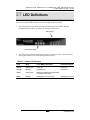
27 LED DEFINITIONS ...................................................................................................................27-4
28 SPECIFICATIONS.....................................................................................................................28-1

52-80420-00 A0
1-1
1 Overview
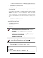
This user guide provides instructions for installing and configuring the AccessLinX VoIP
Gateways. This chapter includes an overview of these products and information for obtaining
technical assistance. The following chapters include brief installation instructions and full
configuration and software-upgrade instructions for using and managing the VoIP Gateway.
AccessLinX, VoIP Gateway and Gateway unit are interchangeable terms throughout this
manual.
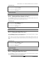
1.1 Product Overview
The AccessLinX units are analog gateways with two Voice-over-IP (VoIP) ports. The unit
enables the use of two independent analog telephone lines or FAX machines to make VoIP
phone calls over the Internet or Intranet. In addition, it enables connecting up to four
computers or segments to the network. Local computers are connected via Ethernet
10/100BaseTX ports. Uplink connection is via either a 100BaseFX SFP or SFF fiber optic or
a 10/100BaseTX copper port.
All Ethernet ports are connected by an advanced switching engine that supports VLANs and
QoS.
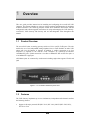
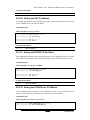
Figure 1-1 AccessLinX VoIP Gateway Front View
1.2 Features
The VoIP Gateway implements up to two simultaneous, independent audio channels and has
the following features:
• Support in all major protocols SIP (RFC 2543, RFC 3261), MCGP (RFC 2705, NCS),
ITU H.323 V2.0

OVERVIEW
52-80420-00 A0
1-2
• Voice coding G.711 (A-law or µ-law) or G.723.1 or G729A/B or G726
•
Full-duplex acoustic echo cancellation with an effective 64ms tail length, -18dB network
echo cancellation
• Comfort noise generation and voice activity detection
• Fax/Modem Tone Detection
• DTMF tone generation and detection
• Call tone generation
•
Caller ID generation
o On-hook and off-hook (CID with call waiting)
o FSK (Bellcore), optional DTMF (Swedish)
•
Call Hold, Transfer and Waiting
• Call Forwarding
• 3-way call (conference)
•
Extremely flexible dial plan options
• Four 10/100Base-TX managed switched Ethernet ports
• Optional optical ports available:
o Single-mode LC 100BaseFX
o
Multi-mode MT-RJ 100BaseFX
• Support of sixteen 802.1Q compatible tagged VLANs
• VLAN support for voice channel
•
Supports assigning priority to voice frames with the 802.1 Priority tag or TOS field
• Advanced error and packet loss concealment technology
• DHCP-compliant IP address selection or fixed IP selection
•
Embedded HTTP server for remote Web browser-based configuration
• SNMP for remote configuration control and monitoring
• Telnet
•
Auto Configuration for mass deployment. Automatic software and configuration upgrades
using TFTP or HTTP
• Display LEDs for status monitoring

OVERVIEW
52-80420-00 A0
1-3
1.3 Laser Safety
The emission produced by the end products described in this guide are under Class 1 emission
levels according to IEC 60825-1 and the FDA 21 CFR 1040.10 and 1040.1. These products
shall not be installed in an optical network handling above Class 1 levels.
1.4 How to Get Help
For technical support, please contact IMC Networks Technical Support at:
Tel: (949) 465-3000; (800) 624-1070 (in U.S. and Canada);
+32-16-550880 (Europe)
Fax: (949) 465-3020
E-Mail: [email protected]
Web:
www.imcnetworks.com

52-80420-00 A0
2-1
2 Pre-Installation Requirements
Before you begin installing your AccessLinX, prepare the site. Make sure that the operating
environment meets the physical conditions suitable for such equipment (see operating
temperature and humidity specifications
in at the end of this document).
2.1 Supporting Equipment Requirements
To set up and use an AccessLinX VoIP Gateway unit you need:
•
LAN cables (copper or fiber, depending on the Gateway’s LAN ports) to connect
the VoIP Gateway, PCs, and your local network.
• Use a cross cable for the Ethernet 10/100Base-TX connections from the Gateway to
another Gateway or to a switch or hub.
• Use a straight cable to connect the unit to computer devices.
•
The call management devices and applications appropriate for the call protocol
installed on the VoIP Gateway (H.323, MGCP, or SIP).
• One or Two analog phones or fax machines.
2.2 Telephones and Accessories
The VoIP Gateway supports all standard analog DTMF telephones and accessories, including:
• Single-line touch-tone telephones.
• Multiple-line touch-tone telephones.
• Touch-tone telephones with redial or speed-dial features.
•
Phones or accessories that support Caller ID.
• Answering machines with touch-tone support.
• Phones or accessories that support Distinctive Ring.
• Fax machines
NOTE Pulse-dial telephones and accessories are not supported.

52-80420-00 A0
3-1
3 Gateway Installation
The AccessLinX must be powered by an external UL listed limited power
source or Class II power source (AC/DC adapter), rated input: 100-240
[email protected], 47-63Hz, [email protected] output.
The phone ports (Phone1 and Phone2) are intended for indoor connections
only and may not be connected to the Telecommunication Network.
3.1 Installing the VoIP Gateway
To install your VoIP Gateway:
1. Unpack the VoIP Gateway unit.
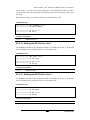
Figures 3-1, 3-2 and 3-3 show the connectors on the rear of the unit for each of three
available gateway models:
• The RJ-11 telephone ports Phone 1 and Phone 2 connect to the telephony devices.
• The PSTN (lifeline) port can be connected as a standby to the public telephone
network. In case of power failure, the phone connected to the Phone1 port will be
automatically switched from VoIP to this line, for regular telephone
communication.
• The LAN ports connect to the LAN, to other VoIP Gateway units and to computers.
• The AUX/Console port, available only in some AccessLinX products, connects to
the serial port on a PC for configuring the unit.
PSTN port Telephone ports LAN ports SFP 100BaseFX
Uplink port
DC power
connector
Figure 3-1 AccessLinX with SFP VoIP Gateway Rear View

GATEWAY INSTALLATION
52-80420-00 A0
3-2
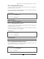
PSTN port Telephone ports LAN ports DC power
connector
Figure 3-2 AccessLinX VoIP Gateway Rear View
PSTN port Telephone ports LAN ports AUX/Console
port (optional)
DC power
connector
Figure 3-3 AccessLinX VoIP Gateway Rear View with AUX/Console Port
IMPORTANT ONLY the PSTN (Life Line) port can be connected to the Public
Telecommunication Network. The phone ports (Phone1 and Phone2)
are intended for indoor connections only and may not be connected to
the Telecommunication Network.
2. Choose a location that is near the devices to be connected and close to an electrical outlet.
Place the Gateway unit on a desktop or other level surface. You may also mount the unit
on the wall, using two wood screws 6.1” (15.5 cm) apart for horizontal positioning or
2.68” (6.8 cm) apart for vertical positioning. Use screws as specified in Table 3-1 below.
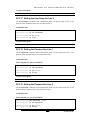
Holes for mounting on the wall are situated at the bottom of the unit (see Figure 3-4).

GATEWAY INSTALLATION
52-80420-00 A0
3-3
Clasp for fastening DC
power-feed cable
Figure 3-4 Bottom of Gateway VoIP Unit
Table 3-1 Mounting screws maximum dimensions
Head diameter (H): Max 9 mm (0.35")
Shank diameter (S): Max 3.5 mm (0.138")
Length (L): 25-30 mm (1"-1.2")
3. Connect to the network via an RJ-45 LAN 100Base-TX connector or the fiber optic
connector of the Gateway unit.
4. If you use an RJ-45 connector, use a cross cable to connect the Gateway unit to another
unit, or to a switch or hub. The cable length must not exceed the maximum length
specified for the media type.
5. Connect any required PC to the unit using a straight cable.
6. Connect the phones to the Gateway unit via the RJ-11 connectors. Up to five phones in
parallel may be connected to each port.
7. Connect the power adapter to the power connector of the unit and to the power source.
Fasten the DC power-feed cable to the clasp at the bottom of the unit to avoid accidental
disconnection.
8. Verify that all system components are properly installed. Make sure that all cable
connectors are securely positioned in the appropriate ports.
9. Do not place any object on top of the unit. Make sure that the ventilation holes on top of
the unit are not blocked.
The Gateway unit is now ready to be configured.
Distance for vertical hanging
= 2.68” ( 6.8 cm)
Distance for horizontal
hanging = 6.1” ( 15.5 cm)
Distance for horizontal
hanging = 6.1” ( 15.5 cm)
Distance for horizontal
hanging = 6.1” ( 15.5 cm)
Distance for horizontal
hanging = 6.1” ( 15.5 cm)
Distance for vertical hanging
= 2.68” ( 6.8 cm)
Distance for horizontal
mounting = 6.1” ( 15.5 cm)
Distance for vertical
mounting = 2.68” ( 6.8 cm)
S
H
L

52-80420-00 A0
4-1
4 Gateway Initial Configuration
and Background Information
To configure the Gateway, proceed as follows:
1. Assign an IP Address to the Gateway.
2. Configure the VoIP protocol parameters appropriate to the protocol installed (H.323 -
Gatekeeper and Dial plan; MGCP - Call agent; SIP - SIP Server).
3. Optionally configure other general parameters.
4. Save the new settings and reset the Gateway unit.
You can use a terminal to configure local basic settings, such as the unit’s IP and most of the
unit’s parameters. For detailed instructions, see Chapter 57: Configuring the Gateway via a
Terminal.
For extended configuration settings, you must use the WEB configuration. You can use SNMP
to configure SNMP parameters, and to control and monitor the Gateway unit. Specific
instructions for configuring various Gateway functions via the WEB are presented in:
• Chapter 9: Configuring the Gateway via the Web
• Chapter 12: Protocol H.323 Configuration via the Web
• Chapter 13: Protocol MGCP Configuration via Telnet
• Chapter 14: Protocol SIP Configuration via Web
• Chapter 16: SNMP Management Overview
Once the Gateway is powered up, addressed, and configured; and the call management device
(Gatekeeper, Call agent or SIP Server) is operating properly, you can place a call.
4.1 Keypad Configuration
Basic configuration commands such as setting factory defaults and changing the IP mode from
DHCP to fixed, or hearing the current IP address announced, can be done by entering
configuration commands using the telephone keypad. Use this option if you have lost normal
access to the Gateway via a PC. The following commands are active ten minutes from boot on
the telephone connected to line 1.
To set the factory defaults:

GATEWAY INITIAL CONFIGURATION AND BACKGROUND
INFORMATION
52-80420-00 A0
4-2
Dial ##3332858 (D,E,F,A,U,L,T). Once the command is accepted, the Management LED on
the front panel will glow a steady green and after about 30 seconds the unit will power up with
factory defaults.
To set the IP mode:
To change the IP mode from DHCP to fixed or vice-versa, dial ##3427937 (D,H,C,P,Y,E,S) for
DHCP or ##342766 (D,H,C,P,N,O) for fixed IP 10.1.0.54 Mask 255.255.0.0. The Management
LED on the front panel will glow a steady green for about 3 seconds and the unit will boot with
the required IP setting.
To hear the current IP address announced over the headset:
Dial ## 472337 (I,P,A,D,D,R).
4.1.1 Keypad Configuration for MGCP
If the Keypad Configuration option is used before the Gateway is registered with the Call
Agent, dial tone and other tones like “busy” will not be generated. To use the Keypad
Configuration option, dial a valid Keypad Configuration sequence. If the “dot” confirmation is
not heard after a short period, put the handset on the hook and repeat the dialed sequence.
4.2 Understanding DHCP
DHCP (Dynamic Host Configuration Protocol) provides a framework for passing configuration
information to hosts on a TCP/IP network. DHCP, based on the Bootstrap Protocol (BOOTP),
adds the capability of automatic allocation of reusable network addresses and additional
configuration options. DHCP captures the behavior of BOOTP relay agents and DHCP
participants can interoperate with BOOTP participants.
DHCP provides configuration parameters to Internet hosts. DHCP consists of two components:
a protocol for delivering host-specific configuration parameters from a DHCP Server to a host
and a mechanism for allocating network addresses to hosts.
DHCP is built on a client-server model, where designated DHCP Server hosts allocate network
addresses and deliver configuration parameters to dynamically configured hosts. Throughout
the remainder of this document, the term
server
refers to a host providing initialization
parameters through DHCP, and the term client refers to a host requesting initialization
parameters from a DHCP Server.
DHCP supports three mechanisms for IP address allocation:
• Automatic allocation - DHCP assigns a permanent IP address to a client.
• Dynamic allocation - DHCP assigns an IP address to a client for a limited period of time
(or until the client explicitly relinquishes the address). Dynamic allocation allows automatic
reuse of an address that is no longer needed by the client to which it was assigned. Thus,
dynamic allocation is particularly useful for assigning an address to a client that will be
connected to the network only temporarily or for sharing a limited pool of IP addresses
among a group of clients that do not need permanent IP addresses. Dynamic allocation may
also be a good choice for assigning an IP address to a new client being permanently

GATEWAY INITIAL CONFIGURATION AND BACKGROUND
INFORMATION
52-80420-00 A0
4-3
connected to a network where IP addresses are scarce and it is important to reclaim them
when old clients are retired.
• Manual allocation - a client's IP address is assigned by the network administrator, and
DHCP is used simply to convey the assigned address to the client. A particular network will
use one or more of these mechanisms, depending on the policies of the network
administrator. Manual allocation allows DHCP to be used to eliminate the error-prone
process of manually configuring hosts with IP addresses in environments where (for
whatever reasons) it is desirable to manage IP address assignment outside of the DHCP
mechanisms.
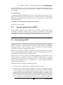
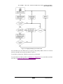
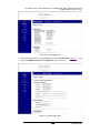
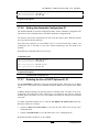
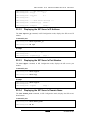
As shown in Figure 4-1, the parameter negotiation starts with a DHCPDISCOVER broadcast
message from the client seeking a DHCP Server. The DHCP Server responds with a
DHCPOFFER unicast message offering configuration parameters (such as an IP address, a
MAC address, a domain name, and a lease for the IP address) to the client. The client returns a
DHCPREQUEST broadcast message requesting the offered IP address from the DHCP Server.
The DHCP Server responds with a DHCPACK unicast message confirming that the IP address
has been allocated to the client.
Figure 4-1: Obtaining an IP Address from a DHCP Server
The client may suggest values for the IP address and lease time in the DHCPDISCOVER
message. The client may include the requested IP address option to suggest that a particular IP
address be assigned, and may include the IP address lease time option to suggest the lease time
it would like to have. The requested IP address option is to be filled in only in a
DHCPREQUEST message when the client is verifying network parameters obtained
previously.
If a server receives a DHCPREQUEST message with an invalid requested IP address, the
server should respond to the client with a DHCPNAK message and may choose to report the
problem to the system administrator. The server may include an error message in the message
option.
For setting the Gateway as DHCP client via Telnet see Configuring the Gateway via Telnet
,
and via Web see Configuring the Gateway via the Web
.

GATEWAY INITIAL CONFIGURATION AND BACKGROUND
INFORMATION
52-80420-00 A0
4-4
4.2.1 When Should Clients Use DHCP
A client should use DHCP to reacquire or verify its IP address and network parameters
whenever the local network parameters may have changed (e.g. at the Gateway boot time or
after a disconnection from the local network), as the local network configuration may change
without the client's or user’s knowledge.
If a client has knowledge of a previous network address and is unable to contact a local DHCP
Server, the client may continue to use the previous network address until the lease for that
address expires. If the lease expires before the client can contact a DHCP Server, the client
must immediately discontinue use of the previous network address and may inform local users
of the problem.
4.3 Understanding NAT and NAPT
The goal of the Network Address Translator (NAT) is to provide functionality as if the private
network had globally unique addresses and the NAT device was not present. Basic NAT allows
a one-to-one mapping between one private address and one public address. In its simplest
configuration, the NAT operates on a router connecting two networks together. One of these
networks (designated as inside) is addressed with either private or obsolete addresses that need
to be converted into legal addresses before packets are forwarded onto the other network
(designated as outside). The translation operates in conjunction with routing, so that NAT can
simply be enabled on a customer-side Internet access router when translation is desired.
NAPT (Network Port Address Translator) maps a single public address to one or many internal
addresses and all network IP addresses on the connected computers are local and cannot be seen
by the outside world.
NAT with Port Address Translation (NAPT) is an extension to NAT in that NAPT uses
TCP/UDP ports in addition to network addresses (IP addresses) to map many private network
addresses to a single outside address.
A VoIP Gateway behind NAT might require special settings. For solutions in SIP, see NAT
Settings in Chapter 14: Protocol SIP Configuration via Web.
4.4 Understanding NTP
The NTP is designed to synchronize clocks among devices in a network. NTP runs over User
Datagram Protocol (UDP), which runs over IP. An NTP network usually gets its time from an
authoritative time source, such as a radio clock or an atomic clock attached to a time server.
NTP then distributes this time across the network. NTP is extremely efficient; no more than one
packet per minute is necessary to synchronize two devices to within a millisecond of one
another.
NTP is a tiered time distribution system with redundancy capability. NTP measures delays
within the network and within the algorithms on the machine on which it is running. Using
these tools and techniques, it is able to synchronize clocks to within milliseconds of each other

GATEWAY INITIAL CONFIGURATION AND BACKGROUND
INFORMATION
52-80420-00 A0
4-5
when connected on a Local Area Network and within hundreds of milliseconds of each other
when connected to a Wide Area Network. The tiered nature of the NTP time distribution tree
enables a user to choose the accuracy needed by selecting a level (stratum) within the tree for
machine placement. A time server placed higher in the tree (lower stratum number), provides a
higher likelihood of agreement with the UTC time standard.
You should use the security features of NTP to avoid the accidental or malicious setting of an
incorrect time by using an encrypted authentication mechanism.
NTP has become a standard for internet time synchronization. Most importantly, there are more
than 100000 free NTP time servers in the world.
For setting the IP address of the NTP server via Web see Section Clock Localization
.
4.4.1 Daylight Saving Time (Summer Time)
You can configure your Gateway to observe the Daylight Saving Time (DST) in your area. This
way, whenever the system time is updated using a time server located in a different time area, it
will be automatically corrected with the local DST time offset.
The DST is followed by the U.S. standards. You can have the Gateway advance the clock one
hour at 2:00 a.m. on the first Sunday in April and move back the clock one hour at 2:00 a.m. on
the last Sunday in October. You can also explicitly specify the start and end dates and times and
whether or not the time adjustment recurs every year.
For enabling automatically adjust the internal clock to daylight saving time according to the
local time zone via Web see Section Clock Localization
.
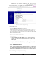
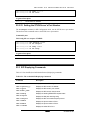
4.5 Understanding Syslog
The system message logging can save messages in a Syslog server. The system message
logging facility has the following features:
• It provides you with logging information for monitoring and troubleshooting.
• It allows you to select the types of logging information to be captured.
•
It allows you to select the destination of captured logging information.
You can specify which system messages should be executed, based on their severity level (see
Table 4-1). You can monitor system messages by viewing the logs on a Syslog server.

GATEWAY INITIAL CONFIGURATION AND BACKGROUND
INFORMATION
52-80420-00 A0
4-6
Table 4-1: Log Message Severity Levels
Severity Level Keyword Description
0 emergency Internal error occurred. The Gateway reached a crash
state and cannot continue to operate.
1 alert Internal error occurred. The Gateway might operate
incorrectly.
2 critical Internal error or non supported event occurred.
3 error Error on a setting done by user.
4 warning Warning on a setting done by user.
5 notification Notifies on configuration setting.
6 information Informs on state changes.
7 debug Debug message to be used by Technical Support.
For setting the Syslog server IP address and the log message severity level via Web see Section
Syslog Server Configuration
.
4.5.1 Remote Logging
To enable remote logging on a UNIX Syslog host facility, follow these steps:
1. Configure the Syslog host to accept and log messages.
2. Enable remote logging by using the enable syslog command.
3. Configure remote logging by using the following command:
config syslog {add} <ipaddress> <facility> {<severity>}
4. Specify the following:
— ipaddress — The IP address of the Syslog host.
— facility — The Syslog facility level for local use. Options include
local0
through
local7
.
— severity — Filters the log to display message with the selected severity or higher (more
critical).
Severities include (in order)
emergency
,
critical
,
alert
,
error
,
warning
,
notice
,
info
, and
debug. If not specified, all messages are sent to the Syslog host.
Page is loading ...
Page is loading ...
Page is loading ...
Page is loading ...
Page is loading ...
Page is loading ...
Page is loading ...
Page is loading ...
Page is loading ...
Page is loading ...
Page is loading ...
Page is loading ...
Page is loading ...
Page is loading ...
Page is loading ...
Page is loading ...
Page is loading ...
Page is loading ...
Page is loading ...
Page is loading ...
Page is loading ...
Page is loading ...
Page is loading ...
Page is loading ...
Page is loading ...
Page is loading ...
Page is loading ...
Page is loading ...
Page is loading ...
Page is loading ...
Page is loading ...
Page is loading ...
Page is loading ...
Page is loading ...
Page is loading ...
Page is loading ...
Page is loading ...
Page is loading ...
Page is loading ...
Page is loading ...
Page is loading ...
Page is loading ...
Page is loading ...
Page is loading ...
Page is loading ...
Page is loading ...
Page is loading ...
Page is loading ...
Page is loading ...
Page is loading ...
Page is loading ...
Page is loading ...
Page is loading ...
Page is loading ...
Page is loading ...
Page is loading ...
Page is loading ...
Page is loading ...
Page is loading ...
Page is loading ...
Page is loading ...
Page is loading ...
Page is loading ...
Page is loading ...
Page is loading ...
Page is loading ...
Page is loading ...
Page is loading ...
Page is loading ...
Page is loading ...
Page is loading ...
Page is loading ...
Page is loading ...
Page is loading ...
Page is loading ...
Page is loading ...
Page is loading ...
Page is loading ...
Page is loading ...
Page is loading ...
Page is loading ...
Page is loading ...
Page is loading ...
Page is loading ...
Page is loading ...
Page is loading ...
Page is loading ...
Page is loading ...
Page is loading ...
Page is loading ...
Page is loading ...
Page is loading ...
Page is loading ...
Page is loading ...
Page is loading ...
Page is loading ...
Page is loading ...
Page is loading ...
Page is loading ...
Page is loading ...
Page is loading ...
Page is loading ...
Page is loading ...
Page is loading ...
Page is loading ...
Page is loading ...
Page is loading ...
Page is loading ...
Page is loading ...
Page is loading ...
Page is loading ...
Page is loading ...
Page is loading ...
Page is loading ...
Page is loading ...
Page is loading ...
Page is loading ...
Page is loading ...
Page is loading ...
Page is loading ...
Page is loading ...
Page is loading ...
Page is loading ...
Page is loading ...
Page is loading ...
Page is loading ...
Page is loading ...
Page is loading ...
Page is loading ...
Page is loading ...
Page is loading ...
Page is loading ...
Page is loading ...
Page is loading ...
Page is loading ...
Page is loading ...
Page is loading ...
Page is loading ...
Page is loading ...
Page is loading ...
Page is loading ...
Page is loading ...
Page is loading ...
Page is loading ...
Page is loading ...
Page is loading ...
Page is loading ...
Page is loading ...
Page is loading ...
Page is loading ...
Page is loading ...
Page is loading ...
Page is loading ...
Page is loading ...
Page is loading ...
Page is loading ...
Page is loading ...
Page is loading ...
Page is loading ...
Page is loading ...
-
 1
1
-
 2
2
-
 3
3
-
 4
4
-
 5
5
-
 6
6
-
 7
7
-
 8
8
-
 9
9
-
 10
10
-
 11
11
-
 12
12
-
 13
13
-
 14
14
-
 15
15
-
 16
16
-
 17
17
-
 18
18
-
 19
19
-
 20
20
-
 21
21
-
 22
22
-
 23
23
-
 24
24
-
 25
25
-
 26
26
-
 27
27
-
 28
28
-
 29
29
-
 30
30
-
 31
31
-
 32
32
-
 33
33
-
 34
34
-
 35
35
-
 36
36
-
 37
37
-
 38
38
-
 39
39
-
 40
40
-
 41
41
-
 42
42
-
 43
43
-
 44
44
-
 45
45
-
 46
46
-
 47
47
-
 48
48
-
 49
49
-
 50
50
-
 51
51
-
 52
52
-
 53
53
-
 54
54
-
 55
55
-
 56
56
-
 57
57
-
 58
58
-
 59
59
-
 60
60
-
 61
61
-
 62
62
-
 63
63
-
 64
64
-
 65
65
-
 66
66
-
 67
67
-
 68
68
-
 69
69
-
 70
70
-
 71
71
-
 72
72
-
 73
73
-
 74
74
-
 75
75
-
 76
76
-
 77
77
-
 78
78
-
 79
79
-
 80
80
-
 81
81
-
 82
82
-
 83
83
-
 84
84
-
 85
85
-
 86
86
-
 87
87
-
 88
88
-
 89
89
-
 90
90
-
 91
91
-
 92
92
-
 93
93
-
 94
94
-
 95
95
-
 96
96
-
 97
97
-
 98
98
-
 99
99
-
 100
100
-
 101
101
-
 102
102
-
 103
103
-
 104
104
-
 105
105
-
 106
106
-
 107
107
-
 108
108
-
 109
109
-
 110
110
-
 111
111
-
 112
112
-
 113
113
-
 114
114
-
 115
115
-
 116
116
-
 117
117
-
 118
118
-
 119
119
-
 120
120
-
 121
121
-
 122
122
-
 123
123
-
 124
124
-
 125
125
-
 126
126
-
 127
127
-
 128
128
-
 129
129
-
 130
130
-
 131
131
-
 132
132
-
 133
133
-
 134
134
-
 135
135
-
 136
136
-
 137
137
-
 138
138
-
 139
139
-
 140
140
-
 141
141
-
 142
142
-
 143
143
-
 144
144
-
 145
145
-
 146
146
-
 147
147
-
 148
148
-
 149
149
-
 150
150
-
 151
151
-
 152
152
-
 153
153
-
 154
154
-
 155
155
-
 156
156
-
 157
157
-
 158
158
-
 159
159
-
 160
160
-
 161
161
-
 162
162
-
 163
163
-
 164
164
-
 165
165
-
 166
166
-
 167
167
-
 168
168
-
 169
169
-
 170
170
-
 171
171
-
 172
172
-
 173
173
-
 174
174
-
 175
175
-
 176
176
-
 177
177
-
 178
178
-
 179
179
-
 180
180


IMC Networks AccessLinX User manual
- Category
- Networking
- Type
- User manual
Ask a question and I''ll find the answer in the document
Finding information in a document is now easier with AI
Other documents
-
Abocom DVG-2101SP User manual
-
-
Patton electronic SN463X User manual
-
 Hybertone GoIP_4 User manual
-
OKI BMG7012 User manual
-
Avaya BSGX4e User guide
-
 Teledex IP250DVoIP User manual
-
Polycom VBP 4350 Series User manual
-
Poly VBP 4300 Series User guide
-
Edgewater Networks 4300T User manual

