
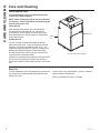
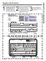
Write the model and serial
numbers here:
Model # _________________
Serial # _________________
You can find them on a label on
the top panel.
GE is a trademark of the General Electric Company. Manufactured under trademark license.
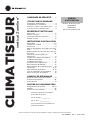
OWNER’S MANUAL
AIR CONDITIONER
Zoneline
®
Vertical
49-5000431 Rev. 1 10-19 GEA
Heat Pump Models
AZ91H18D*E
AZ91H18E*E
Large Chassis
ESPAÑOL
For a Spanish version of this
manual, visit our Website at
www.zoneline.com.
Para consultar una version
en español de este manual
de instrucciones, visite nuestro
sitio de internet
www.zoneline.com.
FRANÇAIS
For a French version of this
manual, visit our Website at
www.zoneline.com.
Pour un version français de
ce manuel d’utilisation, veuillez
visiter notre site web à l’adresse
www.zoneline.com.
SAFETY INFORMATION .........3
USING THE ZONELINE
Power Disconnect .....................4
Ventilation Control .....................4
Room Freeze Protection ................4
About your Heat Pump .................4
CARE AND CLEANING
Air Filters .............................5
Drain .................................5
Indoor/Outdoor Coils ..................6
Base Pan .............................6
INSTALLATION INSTRUCTIONS
Preparation ........................ 7, 8
Ductwork .............................8
Accessories ...........................9
Return Air Grille Options. . . . . . . . . . . . . . .10
Utility Closet Connection Locations ..10
Typical Closet and Dimensions ......... 11
Installation Sequence .................12
Plenum Installation ...................12
Grille Installation .....................12
Build Base Platform ..................12
Drain connection .....................13
Connect the Top Duct .................14
Thermostat .......................15, 16
Electrical Connection ...............17, 18
Installation Checklist ..................18
Connect Power .......................18
TROUBLESHOOTING TIPS
Normal Operating Sounds .............19
Troubleshooting Tips ................. 20
Error Codes ..........................21
CONSUMER SUPPORT
Product Registration ..............23, 24
Warranty ............................25
Consumer Support ................... 26

2 49-5000431 Rev. 1
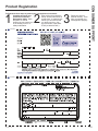
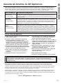
THANK YOU FOR MAKING GE APPLIANCES A PART OF YOUR HOME.
Whether you grew up with GE Appliances, or this is your first, we’re happy to have you in the family.
We take pride in the craftsmanship, innovation and design that goes into every GE Appliances
product, and we think you will too. Among other things, registration of your appliance ensures that we
can deliver important product information and warranty details when you need them.
Register your GE appliance now online. Helpful websites and phone numbers are available in the
Consumer Support section of this Owner’s Manual. You may also mail in the pre-printed registration
card included in the back of this manual.

49-5000431 Rev. 1 3
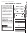
READ AND SAVE THESE INSTRUCTIONS
IMPORTANT SAFETY INFORMATION
READ ALL INSTRUCTIONS BEFORE USING THE APPLIANCE
SAFETY INFORMATION
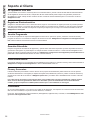
For your safety, the information in this manual must be followed to minimize the risk of fire, explosion,
electric shock, property damage, personal injury, or loss of life.
SAFETY PRECAUTIONS
WARNING
Ŷ7KLV=RQHOLQHPXVWEHSURSHUO\LQVWDOOHGLQDFFRUGDQFHZLWKWKH,QVWDOODWLRQ,QVWUXFWLRQVEHIRUHLWLV
XVHG6HHWKH,QVWDOODWLRQ,QVWUXFWLRQVLQWKHEDFNRIWKLVPDQXDO
Ŷ'LVFRQQHFWWKH=RQHOLQHDWWKHIXVHER[RUFLUFXLWEUHDNHUEHIRUHPDNLQJDQ\UHSDLUV
NOTE: We strongly recommend that any servicing be performed by a qualified individual.
Ŷ$OODLUFRQGLWLRQHUVFRQWDLQUHIULJHUDQWVZKLFKXQGHUIHGHUDOODZPXVWEHUHPRYHGSULRUWRSURGXFW
GLVSRVDO,I\RXDUHJHWWLQJULGRIDQROGSURGXFWZLWKUHIULJHUDQWVFKHFNZLWKWKHFRPSDQ\KDQGOLQJ
disposal about what to do.
Ŷ7KHVH5$DLUFRQGLWLRQLQJV\VWHPVUHTXLUHFRQWUDFWRUVDQGWHFKQLFLDQVWRXVHWRROVHTXLSPHQW
and safety standards approved for use with this refrigerant. DO NOT use equipment certified for
R22 refrigerant only.

49-5000431 Rev. 1
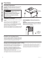
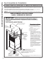
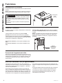
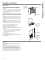
Power Disconnect
7KHSRZHUGLVFRQQHFWLVORFDWHGRQWKHIURQWRIWKH
=RQHOLQH
NOTE:7KHSRZHUGLVFRQQHFWGRHVQRWUHPRYHSRZHUIURP
WKHWHUPLQDOEORFNORFDWHGXQGHUWKHFRQWUROER[SDQHO
FEATURES OF THE ZONELINE
Features
About Your Heat Pump (on some models)
+HDWSXPSVFDQUHGXFHRSHUDWLQJFRVWVE\H[FKDQJLQJ
heat from the outside air—even when the outside
temperature is below freezing— and releasing that heat
indoors.
7RJHWWKHEHVWHFRQRPLFEHQHILWIURP\RXUKHDWSXPS
don’t change the room thermostat setting very often.
Raising the heat setting 2–3 degrees will cause the
=RQHOLQHWRXVHLWVHOHFWULFKHDWLQJHOHPHQWVLQRUGHUWR
reach the new temperature setting quickly.
7KHUHLVDWKUHHPLQXWHPLQLPXPFRPSUHVVRUUXQWLPHDW
any setting to prevent short cycling.
7KHLQGRRUIDQPRWRUVWDUWVEHIRUHWKHFRPSUHVVRUDQG
stops after the compressor cycles off.
7KHHOHFWULFKHDWLQJHOHPHQWVXVHPXFKPRUHHOHFWULFLW\
than heat pumps and cost more to operate.
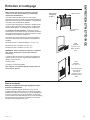
Ventilation Control
7KHYHQWLODWLRQFRQWUROOHYHULVORFDWHGRQWKHIURQWRIWKH
=RQHOLQHXQLW
When the lever is in the CLOSE position, only the air inside
the room is circulated and filtered.
When the lever is in the OPEN position, some outdoor air
ZLOOEHGUDZQLQWRWKHURRP7KLVZLOOUHGXFHWKHKHDWLQJRU
cooling efficiency.
To close the vent, move the slide lever up.
To open the vent, move the slide lever down.
Energy Tip: Keep the vent control in the CLOSE position.
7KHURRPDLUZLOOEHILOWHUHGDQGFLUFXODWHG
NOTE: Ventilation openings are not intended to be the
source of make-up air for building ventilation systems due to
the additional heating and cooling loads generated.
Power
'LVFRQQHFW
Room Freeze Protection
7KLVIHDWXUHZLOOPRQLWRUWKHLQGRRUURRPFRQGLWLRQVDQGLQ
WKHHYHQWWKDWWKHURRPIDOOVEHORZWKHXQLWZLOOF\FOHRQ
KLJKIDQZLWKWKHHOHFWULFKHDWHU7KLVRFFXUVUHJDUGOHVVRI
mode as long as power is applied to the unit.
Ventilation
Control Slide
Lever
WARNING
Electric Shock Hazard
%HIRUHVHUYLFLQJGLVFRQQHFWSRZHUWRWKH=RQHOLQHDW
WKHIXVHER[RUFLUFXLWEUHDNHUDQGSXOORXWHOHFWULFDO
disconnect on front of the chassis.
Failure to do so can result in personal injury and/or
death.

49-5000431 Rev. 1 5
Care and Cleaning
CARE AND CLEANING
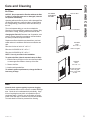
Air Filters
NOTICE: Do not operate the Zoneline without the filter
in place. If a filter becomes torn or damaged, it should
be replaced immediately.
Operating without the filter in place or with a damaged filter
will allow dirt and dust to reach the indoor coil and reduce
the cooling/heating, performance, airflow and efficiency of
the unit.
7KHPRVWLPSRUWDQWWKLQJ\RXFDQGRWRPDLQWDLQWKH
=RQHOLQHLVWRFKDQJHWKHILOWHUDWOHDVWHYHU\GD\V'LUW\
filters reduce cooling, heating performance and air flow.
Changing the filter will: 'HFUHDVHFRVWRIRSHUDWLRQVDYH
HQHUJ\SUHYHQWFORJJHGKHDWH[FKDQJHUFRLOVDQGUHGXFH
the risk of premature component failure.
Replacement filters should be purchased from your local
retailer where air conditioner and furnace accessories are
sold.
)LOWHUVL]HIRUIURQWRIXQLWLV´[´[´
)LOWHUVL]HIRU5$95*LV´[´[´
)LOWHUVL]HIRU5$95*LV´[´[´
NOTE: Use only one filter in the installation.
To replace the filter (chassis mounted return air filter):
6OLGHWKHILOWHUWRWKHULJKWRUOHIWWRFOHDUWKHILOWHUKROGHUV
or rotate upper filter holder to clear top of the filter.
2. Remove the filter.
,QVWDOOQHZGLVSRVDEOHILOWHU
To maintain optimum performance, change the filter at
least every 30 days.
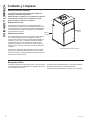
Drain
Clean the drain system regularly to prevent clogging.
7KHFRQGHQVDWHGUDLQPXVWEHURXWHGWRDVXLWDEOHGUDLQDJH
area. Check the unit condensate drain periodically. Keep
it free of anything that may block or impeded the flow of
FRQGHQVDWHZDWHU,IWKHUHLVDQ\DFFXPXODWLRQRIIRUHLJQ
matter in the drain pipe, it should be removed and cleaned.
7KHHQWLUHGUDLQOLQHPXVWEHSURWHFWHGIURPIUHH]LQJ
Unit-mounted filter
Remove filter
Return air grille
RAVRG2
Filter
´[´[´
To remove
and replace
the filter:
Access-panel with
return air grille
Hinge on left Side
of door
RAVRG3
Filter
´[´[´

6 49-5000431 Rev. 1
CARE AND CLEANING
Care and Cleaning
Indoor/Outdoor Coils
The Indoor/Outdoor coils on the Zoneline should be
cleaned and checked regularly.
NOTE: When cleaning the coils do not use acid based
coil cleaners. Care must be taken to avoid bending the
aluminum fins on the coils.
Indoor-Air Coil
Minor amounts of lint and dirt may pass through the
ILOWHUDQGFROOHFWRQWKHLQGRRUDLUFRLO7KHVHPLQRU
accumulations can be carefully vacuumed away with a
brush attachment on a vacuum cleaner or professionally
steam cleaned away.
Outdoor-Air Coil
7KHXQLW¶VRXWGRRUDLULQWDNHDQGRXWGRRUDLUH[KDXVW
SDWKVPXVWUHPDLQFOHDU&KHFNWKHRXWGRRUDLUH[KDXVW
IUHTXHQWO\.HHSLWIUHHRIDOOGHEULVVQRZRULFH7KH
outdoor-air intake should also be kept free of obstructions.
%ORFNLQJWKHRXWGRRUDLUH[KDXVWRURXWGRRUDLULQWDNH
opening will reduce the efficiency of your unit and could
cause premature compressor failure.
,QVSHFWLRQDQGFOHDQLQJRIWKHRXWGRRUDLUFRLOVPD\UHTXLUH
the unit to be removed from the closet. See servicing
section of this manual for instructions on how to remove the
unit.
,QGRRUFRLOV
Have the coils cleaned regularly.
Outdoor
coils
Base Pan
,QVRPHLQVWDOODWLRQVGLUWRURWKHUGHEULVPD\EHEORZQLQWR
the unit from the outside and settle in the base pan (the
bottom of the unit).
,QVRPHDUHDVRIWKH8QLWHG6WDWHVD³JHOOLNH´VXEVWDQFH
may be present in the base pan.
Check it periodically and clean, if necessary.

49-5000431 Rev. 1 7
Installation Preparation
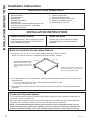
INSTALLATION INSTRUCTIONS
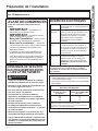
BEFORE YOU BEGIN
Read these instructions completely and carefully.
•
IMPORTANT – Save these
instructions for local inspector’s use.
•
IMPORTANT – Observe all
governing codes and ordinances.
• Note to Installer – Be sure to leave these
instructions with the owner.
• Note to Owner – Keep these instructions for
future reference.
• Proper installation is the responsibility of the
installer.
• Product failure due to improper installation is not
covered under the Warranty.
• You must use all supplied parts and use proper
installation procedures as described in these
instructions when installing this air conditioner.
Questions? Call 844-GE4-PTAC (or 844-434-7822 ) or Visit our Website at: GEAppliances.com
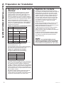
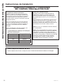
IMPORTANT ELECTRICAL
SAFETY—READ CAREFULLY
• All electrical connections and wiring MUST
be installed by a qualified electrician.
• Follow the National Electrical Code (NEC) and local
codes and ordinances.
• For personal safety, this Zoneline must be properly
grounded.
• Protective devices (fuses or circuit breakers)
acceptable for Zoneline installations are specified
on the nameplate of each unit.
• Do not use an extension cord with this unit.
• Aluminum building wiring may present special
problems—consult a qualified electrician.
• When the unit is not running there is still voltage to
the electrical controls.
• Disconnect the power to the unit before servicing
by removing the branch circuit fuses or turning the
circuit breakers off at the panel.
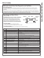
WARNING
ELECTRICAL
REQUIREMENTS
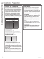
Wire Size Use ONLY wire size recommended for
single outlet branch circuit
Fuse/Circuit
Breaker
Use ONLY type and size fuse or HACR
circuit breaker indicted on units rating
plate. Proper over current protection
to the units is the responsibilty of the
owner.
Grounding 8QLW0867EHJURXQGHGIURPEUDQFK
circuit to unit, or through separate
ground wire provided on permanently
connected units. Be sure that branch
circuit is grounded.
Wire Sizing Use recommended wire size given
in tables and install a single branch
circuit. All wiring must comply with
local and national codes.
NOTE: Use copper conductors only.
NOTE: All field wiring must comply with NEC and
local codes. It is the responsibility of the installer
to insure that the electrical codes are met.
• Use ONLY the wiring size recommended for single
outlet branch circuit.
• Proper current protection is the responsibility of the
owner.
Recommended branch circuit wire sizes*
Nameplate
maximum circuit
breaker size
AWG Wire size**
$
$
$
AWG – American Wire Gauge
6LQJOHFLUFXLWEUHDNHUIURPPDLQER[
%DVHGRQ¶RUOHVVRIFRSSHUZLUHVLQJOHLQVXODWHGFRQGXFWRU
DW&:LUHVL]HVDUHSHU1(&
NOTE: Use copper conductors only.

8 49-5000431 Rev. 1
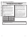
Installation Preparation
INSTALLATION INSTRUCTIONS
Ductwork
7KHVXSSO\GXFWV\VWHPVKRXOGEHGHVLJQHGYLD
a recognized method such as the equal friction
method, or velocity reduction method, using the
appropriate duct calculator(s) for the type(s) of duct
LHPHWDOGXFWGXFWERDUGRUIOH[GXFWEHLQJXVHG
LQWKHV\VWHP7KHGXFWV\VWHPVKRXOGEHGHVLJQHG
IRUDPD[LPXPIULFWLRQUDWHRI´ZDWHUFROXPQ
taking into consideration all fittings, registers and/or
diffusers. DO NOT operate unit without a supply
duct attached.
7KHUHWXUQDLUWR6398VHULHVXQLWV0867127EH
GXFWHGDQGDOOXQLWV0867KDYHDIUHHUHWXUQDLU
configuration to perform properly.
7KHWRWDOIORZUDWH&)0DQGH[WHUQDOVWDWLFSUHVVXUH
(ESP) available can be estimated from the charts to
the left. Use these charts to select your fan speed
setting.
7KHFROODURQWRSRIWKHXQLWDFFHSWVVWDQGDUG
´
duct.
3XOODOOGXFWWLJKW([WUDGXFWVODFNFDQJUHDWO\
increase static pressure.
NOTICE: Flex duct can collapse and
cause airflow restrictions. Do not use flex duct
for 90° bends or unsupported runs of 5 ft. or
more.
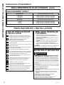
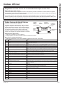
Indoor Air Flow Data
,QGRRUDLUIORZPD\EHGHWHUPLQHGE\PHDVXULQJWKH
H[WHUQDOVWDWLFSUHVVXUH(63RIWKHGXFWV\VWHP
using an inclined manometer or magnehelic gauge,
WKHQFRQVXOWLQJFKDUW³$´WRGHWHUPLQHDFWXDODLUIORZ
Use the air flow correction multipliers contained in
FKDUW³%´WRGHWHUPLQHDFFXUDWHDLUIORZXQGHUWKH
listed conditions. Under no circumstances should
WKH6398HTXLSPHQWEHRSHUDWHGDWDQH[WHUQDO
VWDWLFSUHVVXUHLQH[FHVVRI´:&2SHUDWLRQ
of the SPVU under these conditions will result in
inadequate air flow leading to poor performance and/
or premature component failure.
Chart A - CFM - Determining the Indoor CFM
Models
$=+'(
$=+((
Fan Speed Low High
(63³ CFM
´
´
´
´ 325
´ 255
(63 H[WHUQDOVWDWLFSUHVVXUHLQLQFKHVZDWHUFROXPQ
Rated CFM at High Speed:
$=+'($=+((
For single speed thermostats connect to the GL terminal for
/RZ6SHHGRU*+WHUPLQDOIRU+LJK6SHHG7ZRVSHHGFRQWURO
thermostats will use both terminals.
Chart B - Correction Multipliers
Correct CFM (if needed)
Correction Multipliers for:
99
9
Heating
Cooling
Your airflow should be balanced based on many
factors, such as available ESP, room CFM, and
ductwork. Consult an HVAC engineer for proper
DSSOLFDWLRQV([WHUQDOVWDWLFSUHVVXUH(63FDQEH
measured with a manometer or pitot tube. Once this
ESP is established, you can calculate the CFM using
the above chart.
Higher CFMs tend to increase S(16,%/(FDSDFLW\
enhance room circulation and increase duct noise,
while lower CFMs tend to increase L$7(17 capacity
and reduce noise.

49-5000431 Rev. 1
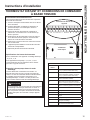
INSTALLATION INSTRUCTIONS
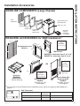
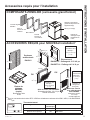
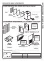
Installation Accessories
ZONELINE COMPONENTS (Large Chassis)
REQUIRED ACCESSORIES for NEW Installation*
Architectural Louver
RAVAL2
Cutout
'LPHQVLRQV
5
/8:[
7
»8´H
A
B
Cutout
'LPHQVLRQV
3
»8´:[
3
»8´H
22-
»2´
22-
»2´
Grille
Kit RAVAL2
([WHULRU
Outside Wall
Part B
,QVLGH
Wall Plenum
Part A
Outside
Wall Plenum
25-
/´
/´
Return Air Grille
RAVRG2
)LOWHU6L]H´[´
Field Supplied
Drain Pan
RAVDP20
(REQUIRED)
,QFOXGHVGUDLQSOXJ
OR
Cutout
'LPHQVLRQV
27´:[
3
»´H
Access Panel with
Return Air Grille
RAVRG3
)LOWHU6L]H´[´
Field Supplied
Wall Plenum
RAVWPT8 - telescopes from 5 1/2” to 8”
RAVWPT14 - telescopes from 8” to 14”
Large Chassis Unit
8QLWKHLJKW´
/8´
3
/8´
58"
29"
'UDLQ3DQ
required
5$9'3
not included
Hinge on left
Side of door
)LOWHU´[´
*
)RUFRQYHUVLRQVIURP$=$=VHULHVWR$=$=VHULHVYHUWLFDODLUFRQGLWLRQHUV5$975$16.LWLV
required.
Model Type Electronic
Thermostat
Kit Number
Heat Pump Models 6-wire 5$.3DQG5$.'
Heat Pump Models 7-wire 5$.)
Wall Thermostat

49-5000431 Rev. 1
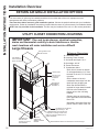
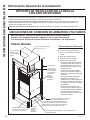
Installation Overview
RETURN AIR GRILLE INSTALLATION OPTIONS
7KHURRPUHWXUQDLUJULOOHPD\EHLQVWDOOHGWRZDUGWKHIURQWRUHLWKHUVLGHRIWKHXQLW,PSURSHUUHWXUQDLU
arrangements will cause performance problems.
There are three indoor return air grille installation options. Choose the option that best suits your installation
UHTXLUHPHQWV)ROORZWKH,QVWDOODWLRQ,QVWUXFWLRQVSURYLGHGZLWKWKHUHWXUQDLUJULOOHDFFHVVRU\IRULQVWDOODWLRQGHWDLOV
NOTE: Use only one filter in the installation.7KHILOWHUPD\EHLQVWDOOHGRQWKHXQLWRULQWKHDFFHVVSDQHOGRRU
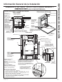
INSTALLATION INSTRUCTIONS
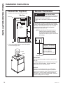
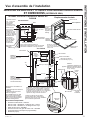
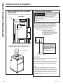
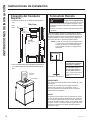
UTILITY CLOSET CONNECTION LOCATIONS
IMPORTANT: Plan and locate plenum, electrical connection,
drains and thermostat carefully to avoid interference. Hard-to-
reach locations will make installation and service difficult!
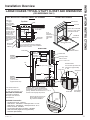
Reference Dimensions
A 7KHUPRVWDWFDEOH
B ,QFRPLQJ3RZHU&RQGXLW
C Unit width and depth: 23-
»8´
D 8QLWKHLJKW´
E3RZHU'LVFRQQHFW
F Condensate drains:
'UDLQKROHLVORFDWHGRQERWWRP
RIXQLWDSSUR[LPDWHO\´IURP
WKHEDFNRIWKHXQLW´IURPWKH
right side .
• On the bottom of the unit
condensate water drips from the
drain hole into the drain pan.
'UDLQ3DQ.LW5$9'3LV
required for large chassis installs.
'UDLQNLWWREHLQVWDOOHGLQWR
plenum prior to the unit being
installed.
3ULPDU\GUDLQFDQH[LWIURPWKH
OHIWRUULJKWVLGHVRIWKH5$9'3
'UDLQ3DQ
• Secondary drain water flows into
plenum from the back of the unit.
C
C
'
5DLVHG3ODWIRUP6XUIDFHUHFRPPHQGHG´PLQLPXPKHLJKW
Large Chassis
8VHULJLGGXFWIRU
bends and tees.
)OH[GXFWPD\
be used for
transitions
only
([WHULRU:DOO
Wall Plenum
5$9:37
5$9:37
)5$9'3GUDLQSDQEHQHDWKXQLW
is required on all large chassis units.
'UDLQSDQPXVWEHLQVWDOOHGSULRUWR
chassis installation
Chassis is
shipped with
vibration isolators
installed.
´&OHDUDQFHRQ
all three sides
minimum for service
and installation
A
B
Unit slides into wall plenum
DSSUR[LPDWHO\´
E
8VHIOH[LEOHRU
hard conduit for
direct connection

49-5000431 Rev. 1
INSTALLATION INSTRUCTIONS
Installation Overview
Side View
Exterior/Outside
Outside wall
Inside wall
Rigid
ductwork
Flexible or
rigid duct
•
3"
min. from front of unit
•
3"
min. from both sides of unit
Plenum cutout
30-⅞ ” H
x 24-⅝” W
Unit
Front Install Clearances
Side Installs not recommended
Outside wall
Drain Pan
Wall plenum
Field supplied
outer flashing
Plenum
opening
Platform Surface
LARGE CHASSIS TYPICAL UTILITY CLOSET AND DIMENSIONS
(FOR REFERENCE ONLY)
Top View
Grille
duct
'RRUDFFHVVSDQHO
3" min. clearance
three sides*
UNIT INSTALLED THROUGH FRONT OF PLENUM
7KHUPRVWDW
connection
Drain Pan Location
Available Accessories
• Architectural Louver - RAVAL2
:DOO3OHQXP5$9:37WHOHVFRSHVIURP
/2´WR´
:DOO3OHQXP5$9:37WHOHVFRSHVIURP´WR´
• Return Air Grille - RAVRG2
• Access Panel with Return Air Grille - RAVRG3
:DOO7KHUPRVWDW'LJLWDODQG3URJUDPPDEOH
5$9'35(48,5('
Plenum
/2´
/2´
´
)LOWHU´[´
Platform
Required
Option 2
Access panel with
return air grille
RAVRG3
Option 1
Return air grille
RAVRG2
(used with field
supplied closet door)
Unit
Unit and drain pan slides into
ZDOOSOHQXPDSSUR[LPDWHO\
´
Platform0LQLPXP´KLJKSODWIRUP
recommended. Height is determined by
architectural location of plenum and wall
opening. Platform size minimum 23-
/´[
/´
PLQLPXPORDGFDSDFLW\SRXQGV
3OHQXPRSHQLQJPXVWEH´
above platform surface for
large chassis installation.
Wall
Plenum
Wall Plenum
7RS6HDO
Bottom Seal
5$9'3
'UDLQ3DQ
Shown with condensate
draining to right. Could
also drain to the left.
Platform Surface
inches of
bottom seal
removed to
place drain
pan
´
'LVFKDUJH2XWOHW
23-
/8´
,WLVUHFRPPHQGHGWROHDYHDGGLWLRQDO
space around the unit to ease installation
and access for service.
Electrical
connection
Plenum is
~´ELJJHU
than unit width
(~´FOHDUDQFH
each side)
'UDLQKROH
ORFDWHG´
from back of the
XQLWDQG´IURP
the right side on
bottom of the
XQLW'UDLQSDQ
5$9'3PXVWEH
installed below the
drain hole to collect
condensation
water.
Platform
Side installs not recommended,
but maybe accomplished
with larger closet and other
accomodations.

49-5000431 Rev. 1
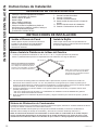
INSTALLATION INSTRUCTIONS
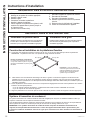
Installation Instructions
3ODQIRUSURSHUHOHFWULFDOVXSSO\GUDLQVDQG
ductwork locations.
,QVWDOOZDOOSOHQXP
,QVWDOOWKHJULOOH
%XLOGDQGLQVWDOOSODWIRUP
,QVWDOOGUDLQSDQ
3ODFHXQLWRQWKHSODWIRUPDQGVOLGHWKHH[WHULRUVLGH
of the unit into the plenum until it is fully seated.
(Unit touches air divider)
INSTALLATION SEQUENCE
7. Connect unit to the ductwork.
8. Connect the thermostat.
&RQQHFWWKHHOHFWULFDOSRZHU
,QVWDOODLUUHWXUQJULOOHRUDFFHVVFRYHU
5HYLHZWKHLQVWDOODWLRQFKHFNOLVW
&KHFNRSHUDWLRQRIWKHXQLW
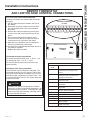
Condensate Disposal System
7KH&RQGHQVDWH'LVSRVDO6\VWHPLQFUHDVHVHQHUJ\HIILFLHQF\XWLOL]LQJDIDFWRU\LQVWDOOHGIDQWKDWVOLQJVWKH
condensate onto the hot outdoor coil.
:KHQKLJKRXWGRRUKXPLGLW\SUHYHQWVWKHVOLQJHUIURPGLVSRVLQJRIDOOFRQGHQVDWHWKHH[FHVVFRQGHQVDWH
RYHUIORZVLQWRWKHFRQGHQVDWHGUDLQSDQDQGRXWRIWKH´LQWHUQDOGUDLQFRQQHFWLRQV
NOTE: If the Condensate Disposal System fails to remove all of the condensate from the unit, any
excess condensate will overflow from a spillway in the rear of the unit directly into the wall plenum,
and drain outside the building. This is your indication that the chassis or drain requires servicing.
Install the Wall Plenum
,QVWDOOWKHZDOOSOHQXP5HIHUWRLQVWUXFWLRQVLQFOXGHG
LQWKHZDOOSOHQXPNLW5$9:3RU5$9:37IRU
proper installation procedures.
Install the Grille
,QVWDOOWKHJULOOH5HIHUWRLQVWUXFWLRQVLQFOXGHG
in the grille kit RAVAL2 for proper installation
procedures.
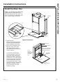
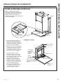
INSTALLATION INSTRUCTIONS
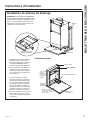
Build and Install the Zoneline Base Platform
1. Construct a 23-
»´PLQ[
»´PLQVTXDUHSODWIRUPZLWKOHJVWRUDLVHWKHSODWIRUP
127(7KHSODWIRUPPXVWKDYHDORDGEHDULQJFDSDFLW\RIOEVPLQLPXP
2. Place the platform in the utility closet with the following clearance between it and the interior surface of the
walls/door/panel:
´PLQIURPIURQWRIWKHXQLW±8QLWWREHLQVWDOOHGWKURXJK)5217RIFDVH
´PLQIURPWZRVLGHVRIWKHXQLW
3. Align the platform with the opening of the wall plenum and secure to the floor using appropriate brackets
and bolts.
23-
»´ min.
Recommended platform height:
3ODWIRUPVXUIDFHVKRXOGEH´
below wall plenum opening. See
3OHQXP,QVWDOODWLRQ,QVWUXFWLRQVIRU
details
23-
»´ min.
127()RUODUJHFKDVVLVXQLWV'UDLQ.LW
5$9'3LVUHTXLUHGWRGUDLQFRQGHQVDWH
ZDWHUWRWKHEXLOGLQJ':9V\VWHP

49-5000431 Rev. 1
Installation Instructions
INSTALLATION INSTRUCTIONS
Install the Drain Pan
NOTE:7+($&&(6625<'5$,13$1
5$9'30867%(,167$//('
%()25(,167$//,1*7+(81,77KLV
NLWLVRQO\XVHGRQWKH%78XQLWV
ZLWKDFKDVVLVKHLJKWRILQFKHV
,QVWDOOGUDLQSDQ
Refer to instructions included in
WKHGUDLQSDQNLW5$9'3IRU
proper installation procedures.
2. Place unit on the platform and
VOLGHWKHH[WHULRUVLGHRIWKH
unit into the plenum until it is
fully seated and unit touches air
divider in plenum.
$QH[WHUQDORULQWHUQDOGUDLQ
must be attached to one of the
two primary drain connections
located to the right or left side of
WKHGUDLQSDQ7KHGUDLQVSLOOZD\
located on the back of the unit is
the secondary drain if required
by state and local codes. A field
supplied secondary condensation
pan may be required. Refer
to the local codes for proper
installation of drain.
Typical Installation
Plenum
Platform
Wall Plenum
7RS6HDO
Bottom Seal
Pan
5$9'3
'UDLQ3DQ
Shown with condensate
draining to right. Could
also drain to the left.
Platform Surface
inches of
bottom seal
removed to
place drain
pan
Drain Pan Kit
RAVDP20

49-5000431 Rev. 1
Installation Instructions
INSTALLATION INSTRUCTIONS
7RSGXFW
Clamp
Connect the Top Duct
,QVWDOOWKHGXFWRQWRWKHDLUGLVFKDUJHRXWOHW
2. Use a field supplied clamp to secure the top duct
to the air discharge outlet.
Side View
Inside wall
Rigid
ductwork
Flexible or
rigid duct
Air
discharge
outlet
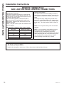
Remote Thermostat
All SPVU units are factory configured to be controlled
by using a single stage heat/cool remote wall mounting
WKHUPRVWDW7KHWKHUPRVWDWPD\EHDXWRRUPDQXDO
changeover as long as the control configuration
matches that of the SPVU unit.
NOTE: See the Remote Thermostat and Low
Voltage Control Connections sections
of this manual and the manual with the
separate thermostat for proper connections
and settings.
IMPORTANT:
7KH=RQHOLQHWKHUPRVWDWFRQQHFWLRQVSURYLGH9
AC only.
,IXVLQJDGLJLWDOHOHFWURQLFZDOOWKHUPRVWDW\RXPXVW
VHWLWWRWKH9$&VHWWLQJ6HHWKH,QVWDOODWLRQ
,QVWUXFWLRQVIRUWKHZDOOWKHUPRVWDW
NOTICE:
'DPDJHWRDZDOOWKHUPRVWDWRUWRWKH=RQHOLQH
electronics can result from improper connections.
([HUFLVHH[WUDDWWHQWLRQZKHQFRQQHFWLQJEOXHDQG
black wires. No line voltage connections should
EHPDGHWRDQ\FLUFXLWLQWKHWKHUPRVWDW,VRODWHDOO
wires in building from line voltage.
7KHUPRVWDW
Unit Connections
Maximum Wiring
Length for Thermostat
Connection to the Unit
IWIRU$:*
IWIRU$:*
IWIRU$:*
AWG – American Wire Gauge
WARNING
Electric Shock Hazard
%HIRUHVHUYLFLQJGLVFRQQHFWSRZHUWRWKH=RQHOLQHDW
WKHIXVHER[RUFLUFXLWEUHDNHUDQGSXOORXWHOHFWULFDO
disconnect on front of the chassis.
Failure to do so can result in personal injury and/or
death.

49-5000431 Rev. 1
Installation Instructions
INSTALLATION INSTRUCTIONS
REMOTE THERMOSTAT
AND LOW VOLTAGE CONTROL CONNECTIONS
To Connect the wall-mounted thermostat
7HUPLQDOFRQQHFWLRQVDUHORFDWHGXQGHUWKHFRQWURO
ER[SDQHO
3XOOWKHSRZHUGLVFRQQHFWORFDWHGLQWKHIURQWRI
the chassis.
'LVFRQQHFWWKHSRZHUFRPLQJLQWRWKHXQLWIURP
the main breaker panel or the closet mounted
disconnect.
5HPRYHWKHFRQWUROER[SDQHOE\UHPRYLQJWKH
IURQWVFUHZVDQGWRSVFUHZVWKDWVHFXUHWKH
panel.
5XQWKHWKHUPRVWDWZLUHVWKURXJKWKHVPDOO
KROHRQWKHWRSRIWKHER[WRUHDFKWKHWHUPLQDO
connections on the right side of the control.
5. Make the wire connections per the instructions
that are included with the thermostat.
6 Once each wire is matched and connected, the unit is
now ready for operation.
5HDWWDFKWKHFRQWUROER[SDQHO
Thermostat terminals requirements
For cooling with electric heat units: C, R, GL, Y, W.
For heat pump units: C, R, GL, Y, W, B.
For two fan speeds, thermostat must have 2 fan
speed selection.
Heat Pump Units During Heat Mode:
7KH%WHUPLQDOPXVWEHFRQWLQXRXVHQHUJL]HG7KH
:WHUPLQDOPXVWKDYH9$&RXWSXWWRFDOOIRUKHDW
7KHFRQWUROERDUGGHFLGHVRQZKHWKHUWRWXUQRQWKH
+HDW3XPS+HDWFRPSUHVVRURU(OHFWULF+HDW7KH
<WHUPLQDOVKRXOGQRWKDYH9$&RXWSXWGXULQJWKH
Electric Heat mode.
,QWHUIDFH'H¿QLWLRQ
Terminal
Code
Wire Connection Function
FP Factory use only.
(Ensure there is not jumper at FP
and F2)
F2 8VHGZLWK)WRSURYLGH9$&WR
H[WHUQDOIDQUHOD\(QVXUHWKHUHLV
no jumper at FP and F2)
) 8VHGZLWK)WRSURYLGH9$&WR
H[WHUQDOIDQUHOD\
' 8VHGZLWK'IRUGHVNFRQWURORQRU
RႇRSHUDWLRQ
' 8VHGZLWK'IRUGHVNFRQWURORQRU
RႇRSHUDWLRQ
C &RPPRQ*URXQG7HUPLQDO
GH Call for High Fan
GL Call for Low Fan
B Call for Heat Pump Reversing Valve
Y Call for Compressor
W Call for Heating
R 93RZHUIURP(OHFWURQLF&RQWURO
WR:DOO7KHUPRVWDW
FP F2 F1 D2 D1 C
GH
GL B Y W R
CAUTION
,PSURSHU&'&ZLULQJPD\GDPDJHWKH=RQHOLQH
HOHFWURQLFVRUFDXVHHUUDWLF=RQHOLQHRSHUDWLRQ1R
Common busing is permitted. A separate wire pair
must be run from each separate controlling switch
WRHDFKLQGLYLGXDO=RQHOLQH
Electronic
Control
Terminal Connection
on unit

49-5000431 Rev. 1
Installation Instructions
INSTALLATION INSTRUCTIONS
REMOTE THERMOSTAT
AND LOW VOLTAGE CONTROL CONNECTIONS
Desk Control Terminals
7KH6398KDVEXLOWLQSURYLVLRQVIRUFRQQHFWLRQWR
DQH[WHUQDOVZLWFKWRFRQWUROSRZHUWRWKHXQLW7KH
switch can be a central desk control system or even
a normally open door switch.
For desk control operation, connect one side of
WKHVZLWFKWRWKH'WHUPLQDODQGWKHRWKHUWRWKH
'WHUPLQDO:KHQHYHUWKHVZLWFKFORVHVWKHXQLW
operation will stop.
127(7KHGHVNFRQWUROV\VWHPDQGVZLWFKHVPXVW
be field supplied.
Maximum Wire Length for Desk Control Switch
Wire Size Maximum Length
IW
#22 IW
IW
IW
IW
Auxiliary Fan Control
7KH6PDUW&HQWHUDOVRKDVWKHDELOLW\WRFRQWUROD
9$&UHOD\WRDFWLYDWHDQDX[LOLDU\RUWUDQVIHUIDQ
7KHRXWSXWVDUHOLVWHGDV)DQG)RQWKHFRQWURO
board.
7RFRQQHFWWKHUHOD\VLPSO\ZLUHRQHVLGHRIWKH
UHOD\WR)DQGWKHRWKHUVLGHWR)$Q\WLPHWKDW
WKHIDQUXQVWKHWHUPLQDOVZLOOVHQGD9$&VLJQDO
WRWKHUHOD\7KHUHOD\PXVWEH9$&P$RU
less.
NOTE:7KHUHOD\DQGDX[LOLDU\IDQVPXVWEHILHOG
supplied.
NOTE:,WLVWKHLQVWDOOHU¶VUHVSRQVLELOLW\WRHQVXUH
that all control wiring connections are made in
accordance with the installation instructions.
,PSURSHUFRQQHFWLRQRIWKHWKHUPRVWDWFRQWUROZLULQJ
and/or tampering with the unit’s internal wiring can
void the equipment warranty and may result in
property damage, personal injury or death.
Air Return Panel/Grille
,QVWDOOWKHDLUUHWXUQJULOOHRUDFHVVFRYHU5HIHUWRLQVWUXFWLRQVLQFOXGHGZLWKWKHNLWFKRVHQ

49-5000431 Rev. 1
Installation Instructions
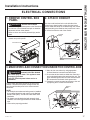
INSTALLATION INSTRUCTIONS
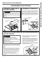
2. ATTACH CONDUIT
Use the round knockout hole on the left side of the
FRQWUROER[WRLQVWDOOFRQGXLWFRPLQJIURPWKHEUDQFK
FLUFXLW,QVWDOODQGFODPSWKHFRQGXLWWKURXJKWKHFRQGXLW
FODPSDQGEULQJZLUHOHDGVLQWRWKHMXQFWLRQER[/HDYH
´RIZLUHIUHHIURPWKHHQGRIWKHFRQGXLW
Conduit
Conduit
clamp
1. REMOVE CONTROL BOX
PANEL
5HPRYHWKHFRQWUROER[SDQHOE\WDNLQJRXWWKH
screws on top of the panel.
&RQWURO%R[3DQHO
ELECTRICAL CONNECTIONS
3. MAKE WIRE LEAD CONNECTIONS INSIDE THE CONTROL BOX
Pull the power disconnect located in the front of the
FKDVVLV'LVFRQQHFWWKHSRZHUFRPLQJLQWRWKHXQLW
from the main breaker panel or the closet mounted
disconnect.
NOTE:
• All electrical connections and wiring must be installed
by a qualified electrician and conform to the National
Electric Code (NEC) and all local codes which have
jurisdiction.
• All chassis must be hard wired with properly sized
breakers. Use HACR type breakers to avoid nuisance
trips.
• Unit must be properly grounded.
0DNHDOOZLUHFRQQHFWLRQVE\XVLQJDSSURSULDWH
UL-listed electrical connectors and techniques.
%HVXUHWKDWDOOZLUHOHDGVDUHLQVLGHWKHFRQWUROER[
DQGQRWSLQFKHGEHWZHHQWKHSDQHODQGWKHXQLW7KH
JUHHQLQVXODWHGJURXQGZLUHIURPWKH=RQHOLQH0867
BE connected to the branch circuit ground wire.
5HSODFHWKHFRQWUROER[SDQHODQGVHFXUHWRWKHXQLW
by replacing the 2 screws removed earlier.
Ground
Wire
Ground
Wire
L1
L2
WARNING
RISK OF ELECTRIC SHOCK
Can cause injury or death. This appliance must
be properly grounded.
Turn OFF electrical power before service or
installation.
WARNING
Electric Shock Hazard
%HIRUHVHUYLFLQJGLVFRQQHFWSRZHUWRWKH=RQHOLQHDW
WKHIXVHER[RUFLUFXLWEUHDNHUDQGSXOORXWHOHFWULFDO
disconnect on front of the chassis.
Failure to do so can result in personal injury and/or
death.

49-5000431 Rev. 1
Installation Instructions
INSTALLATION INSTRUCTIONS
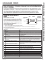
FINAL INSTALLATION
CHECKLIST
Ensure that all installation instructions
concerning clearances around the unit have
been adhered to.
,nspect and ensure that all components and
accessories have been installed properly and
that they have not been damaged during the
installation process.
Wall plenum flashing is installed, plenum level
and calked.
Unit is level, front to back and left to right.
Check to ensure that the unit air filter, indoor
coil, and outdoor coil are free from any
obstructions.
Check to make sure only one air filter is installed
in the system.
Check the condensate water drain(s) to ensure
that they are connected and adequate for the
removal of condensate water and that they meet
approval of the end user.
'XFWZRUNLVFRQQHFWHGDQGVHFXUHWRDLU
discharge outlet.
Secure all access panels (i.e. front cover and/or
FRQWUROER[
Wall thermostat is wired correctly.
Unit is wired correctly.
Ensure that the circuit breaker(s) /fuse(s) and
supply circuit wire size have been sized
correctly.
Ensure the unit has correct line voltage to it, is
on a single circuit and is properly grounded.
Ensure that the entire installation is in
compliance with all applicable national and local
codes and ordinances having jurisdiction.
CONNECT POWER
,IDOOWKHLWHPVRQWKHFKHFNOLVWDUHFRUUHFW
reinstall the power disconnect on the front of the
unit.
7XUQWKHSRZHURQDWWKHPDLQVHUYLFHSDQHO
7XUQRQDQGDGMXVWWKHWKHUPRVWDWVRWKHXQLW
begins to run.
&KHFNIRUSURSHURSHUDWLRQLQHDFKPRGH
,QVWUXFWWKHRZQHURURSHUDWRUUHJDUGLQJWKH
unit’s operation, and the recommended routine
maintenance schedule.
NOTE: Maintaining a log for recording the dates of
maintenance and/or service is recommended, and
should be suggested to the owner or operator of the
equipment.
SERVICING
WARNING
Risk of Electric Shock, can cause injury
or death.
Before servicing, switch power off at
the service panel and lock the area to prevent
power from being switched on accidentally. When
the area cannot be locked, securely fasten a
prominent warning device, such as a tag, to the
service panel.
NOTE: We strongly recommend that any servicing
be performed by a qualified individual.
To remove the unit from the closet.
6ZLWFKWKHZDOOWKHUPRVWDWWRRII
3XOOWKH3RZHU'LVFRQQHFWORFDWHGLQWKHIURQWRIWKH
chassis.
7XUQRIIDOOSRZHUFRPLQJLQWRWKHXQLWDWWKHPDLQ
breaker panel or the closet mounted disconnect.
'LVFRQQHFWWKHHOHFWULFDOFRQQHFWLRQDWWKHXQLW
'LVFRQQHFWWKHGUDLQV\VWHP
'LVFRQQHFWWKHGXFWZRUN
7. Slide the chassis out of the wall plenum.
8. Lift the chassis out of the utility closet.
ELECTRICAL CONNECTIONS (continued)
DIRECT CONNECTION
Heater Wattage
@ 230/208 Volts
Circuit Protective Device
.:
.:
.:
$PS7LPH'HOD\)XVHRU%UHDNHU
$PS7LPH'HOD\)XVHRU%UHDNHU
$PS7LPH'HOD\)XVHRU%UHDNHU
Heater Wattage
@ 265 Volts
Circuit Protective Device
.:
.:
.:
$PS7LPH'HOD\)XVHRU%UHDNHU
$PS7LPH'HOD\)XVHRU%UHDNHU
$PS7LPH'HOD\)XVHRU%UHDNHU
* See NEC for application for 265 Volts.
FINAL INSTALLATION

49-5000431 Rev. 1
TROUBLESHOOTING TIPS
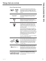
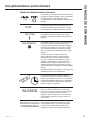
Things that are normal
Normal Operating Sounds
You may hear a pinging noise caused by water
being picked up and thrown against the condenser
RQUDLQ\GD\VRUZKHQWKHKXPLGLW\LVKLJK7KLV
design feature helps remove moisture and improve
efficiency.
You may hear relays click when the controls cycle
on and off or are adjusted to change the room
temperature.
Water will collect in the base pan during high
KXPLGLW\RURQUDLQ\GD\V7KHZDWHUPD\RYHUIORZ
and drip from the outdoor side of the unit.
7KHLQGRRUIDQUXQVFRQWLQXRXVO\ZKHQWKHXQLW
is operating in the cooling mode, unless it is set
WRF\FOH7KLVZLOOFDXVHWKHIDQWRF\FOHRQDQG
off with the compressor. You may also hear a fan
noise stop and start.
7KHUHDUHWLPHVZKHQWKHIDQRQWKHXQLWZLOOUXQ
HYHQZKHQWKHXQLWLVQRWKHDWLQJRUFRROLQJ,IWKH
system is set up to be in continuous fan the indoor
fan will run regardless if the unit may be cooling or
heating. Other times the fan will run longer than the
KHDWLQJFRROLQJF\FOHRUNLFNRQRFFDVLRQDOO\7KLV
is normal and is done to circulate air to improve
room comfort and balance.
,IWKHXQLWLVHTXLSSHGZLWKDPDNHXSDLUYHQWLODWLRQ
system, fans will run continuously.
You may notice a few minutes delay in starting if
\RXWU\WRUHVWDUWWKH=RQHOLQHWRRVRRQDIWHUWXUQLQJ
it off or if you adjust the thermostat right after the
FRPSUHVVRUKDVVKXWRII7KLVLVGXHWRDEXLOWLQ
restart protector for the compressor that causes
a 3-minute delay.
'XULQJWKHGHIURVWF\FOHERWKLQGRRUDQGRXWGRRU
fans stop and the compressor will operate in the
cooling mode to remove frost from the outdoor coil.
After defrost, the unit will restart in electric heat to
quickly warm the room to the desired comfort level.
7RSURWHFWWKHFRPSUHVVRUDQGSUHYHQWVKRUW
cycling, the unit is designed to run for a minimum
of 3 minutes after the compressor starts at any
thermostat setting.
3-Minute
'HOD\
³&/,&.´
S,LENCE
COMPRESSOR
3527(&7,21

49-5000431 Rev. 1
TROUBLESHOOTING TIPS
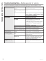
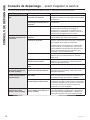
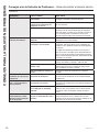
Troubleshooting Tips... Before you call for service
Save time and money! Review the charts on the following pages first and you may not need to call for service.
Problem Possible Cause What To Do
Zoneline does not start. The fuse is blown/circuit breaker
is tripped.
&KHFNWKHKRXVHIXVHFLUFXLWEUHDNHUER[DQGUHSODFH
the fuse or reset the breaker.
The unit is waiting for the
compressor overload protector to
reset.
7KLVLVQRUPDO7KH=RQHOLQHZLOOVWDUWDJDLQDIWHULW
resets.
Power Failure. 7KHUHLVDSURWHFWLYHWLPHGHOD\XSWRPLQXWHVWR
prevent tripping of the compressor overload. For this
reason, the unit may not start normal heating or cooling
for 3 minutes after it turned back on.
Zoneline does not cool or
heat as it should.
Indoor airflow is restricted. Make sure there are not curtains, blinds or furniture
EORFNLQJWKHIURQWRIWKH=RQHOLQH
Outdoor airflow is restricted or
recirculated.
Make sure the architectural louver is not restricted.
7KLVFDQFDXVHWKHXQLWWRF\FOHRIIGXHWRWKH
compressor overload protector.
Outdoor grille must have a minimum of 65% free area.
Non-GE Appliances grills may be too restrictive for
proper performance. Consult your salesperson for
assistance.
The air filter is dirty. &KDQJHWKHILOWHUDWOHDVWHYHU\GD\V6HHWKH&DUH
and Cleaning - Air Filters section
The room may have been hot or
cold.
:KHQWKH=RQHOLQHLVILUVWWXUQHGRQ\RXQHHGWRDOORZ
time for the room to cool down or warm up.
Outdoor air is entering the room. Set the vent control to the closed position.
Burning odor at the start
of heating operation.
Dust on the surface of the heating
elements.
7KLVFDQFDXVHD³EXUQLQJ´RGRUDWWKHEHJLQQLQJRIWKH
KHDWLQJRSHUDWLRQ7KLVVKRXOGTXLFNO\IDGH
The air is not always cool
or hot during operation.
The heat pump is not producing
hot air.
7KLVLVQRUPDO7KHKHDWSXPSZLOOSURGXFHZDUPDLU
but not as hot as air produced when the higher-cost
electric heat is used.
The fan switch may be set to
continuous fan.
7KLVFDXVHVWKHIDQWREORZURRPWHPSHUDWXUHDLU
HYHQZKHQWKHFRPSUHVVRURUKHDWHUF\FOHVRII7KH
continuous air movement provides better overall
temperature control in the cool mode.
The air does not feel warm
enough during heating
operation
The heat pump alone produces air
that feels cooler than desired.
8VHWKH(OHFWULF+HDW2SWLRQ7KLVWXUQVRIIWKHKHDW
SXPSDQGZDUPVZLWKHOHFWULFKHDWRQO\127(
Use of this option will result in increased energy
consumption.
Page is loading ...
Page is loading ...
Page is loading ...
Page is loading ...
Page is loading ...
Page is loading ...
Page is loading ...
Page is loading ...
Page is loading ...
Page is loading ...
Page is loading ...
Page is loading ...
Page is loading ...
Page is loading ...
Page is loading ...
Page is loading ...
Page is loading ...
Page is loading ...
Page is loading ...
Page is loading ...
Page is loading ...
Page is loading ...
Page is loading ...
Page is loading ...
Page is loading ...
Page is loading ...
Page is loading ...
Page is loading ...
Page is loading ...
Page is loading ...
Page is loading ...
Page is loading ...
Page is loading ...
Page is loading ...
Page is loading ...
Page is loading ...
Page is loading ...
Page is loading ...
Page is loading ...
Page is loading ...
Page is loading ...
Page is loading ...
Page is loading ...
Page is loading ...
Page is loading ...
Page is loading ...
Page is loading ...
Page is loading ...
Page is loading ...
Page is loading ...
Page is loading ...
Page is loading ...
Page is loading ...
Page is loading ...
Page is loading ...
Page is loading ...
Page is loading ...
Page is loading ...
-
 1
1
-
 2
2
-
 3
3
-
 4
4
-
 5
5
-
 6
6
-
 7
7
-
 8
8
-
 9
9
-
 10
10
-
 11
11
-
 12
12
-
 13
13
-
 14
14
-
 15
15
-
 16
16
-
 17
17
-
 18
18
-
 19
19
-
 20
20
-
 21
21
-
 22
22
-
 23
23
-
 24
24
-
 25
25
-
 26
26
-
 27
27
-
 28
28
-
 29
29
-
 30
30
-
 31
31
-
 32
32
-
 33
33
-
 34
34
-
 35
35
-
 36
36
-
 37
37
-
 38
38
-
 39
39
-
 40
40
-
 41
41
-
 42
42
-
 43
43
-
 44
44
-
 45
45
-
 46
46
-
 47
47
-
 48
48
-
 49
49
-
 50
50
-
 51
51
-
 52
52
-
 53
53
-
 54
54
-
 55
55
-
 56
56
-
 57
57
-
 58
58
-
 59
59
-
 60
60
-
 61
61
-
 62
62
-
 63
63
-
 64
64
-
 65
65
-
 66
66
-
 67
67
-
 68
68
-
 69
69
-
 70
70
-
 71
71
-
 72
72
-
 73
73
-
 74
74
-
 75
75
-
 76
76
-
 77
77
-
 78
78


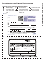
Ask a question and I''ll find the answer in the document
Finding information in a document is now easier with AI
in other languages
- français: GE AZ91H18E3E Le manuel du propriétaire
- español: GE AZ91H18E3E El manual del propietario
Related papers
Other documents
-
Groupe Brandt BLT520SW Owner's manual
-
-
-
Ingersoll-Rand A801X080CM5SAB Installer's Manual
-
 Aube Technologies TH111GFCI-NP 240 VCA User manual
-
Weil-McLain Boiler Sequencing Control (BSC) User manual
-
Johnson Controls YDOA096B21S Installation guide
-
Sanyo SHP-C90GDN Technical Manual
-
Lennox International Inc. HM30 User manual
-
Mitsubishi MSZ-FH09NA Installation guide
