STIEBEL ELTRON VRC-W 400 (E) Operation Instruction
- Type
- Operation Instruction

OPERATION AND INSTALLATION
UTILISATION ET INSTALLATION
BEDIENING EN INSTALLATIE
Central ventilation appliance with heat recovery | VMC centralisée avec récupération
de chaleur | Centraal ventilatietoestel met warmteterugwinning
» VRC-W 400
» VRC-W 400 E

2 | VRC-W 400 (E) www.stiebel-eltron.com
CONTENTS | SPECIAL INFORMATION
SPECIAL INFORMATION
OPERATION
1. General information �����������������������������������������3
1.1 Safety instructions ����������������������������������������������� 3
1.2 Other symbols in this documentation ����������������������� 3
1.3 Information on the unit ����������������������������������������� 3
1.4 Standardised output data �������������������������������������� 3
1.5 Units of measurement ������������������������������������������ 3
2. Safety ���������������������������������������������������������� 4
2.1 Intended use ������������������������������������������������������ 4
2.2 General safety instructions ������������������������������������ 4
2.3 Test symbols ������������������������������������������������������ 4
3. Appliance description ���������������������������������������4
3.1 Frost protection �������������������������������������������������� 4
3.2 Bypass function �������������������������������������������������� 4
4. Settings �������������������������������������������������������5
4.1 Switching the appliance on ������������������������������������ 5
4.2 Programming unit ����������������������������������������������� 5
4.3 Selecting the fan stage ����������������������������������������� 6
4.4 Activating time programs �������������������������������������� 6
4.5 Menu ��������������������������������������������������������������� 6
4.6 Switching off the appliance ������������������������������������ 8
5. Maintenance, cleaning and care ����������������������������8
5.1 Replacement filters ���������������������������������������������� 8
5.2 Filter inspection and replacement ��������������������������� 8
6. Troubleshooting ����������������������������������������������9
INSTALLATION
7. Safety �������������������������������������������������������� 10
7.1 General safety instructions ����������������������������������� 10
7.2 Instructions, standards and regulations ������������������� 10
7.3 Operation of the appliance in buildings with
combustion equipment ���������������������������������������� 10
7.4 Operating the appliance in passive houses ���������������� 11
8. Appliance description ������������������������������������� 11
8.1 Standard delivery ����������������������������������������������� 11
8.2 Accessories ������������������������������������������������������� 11
9. Preparation ������������������������������������������������� 11
9.1 Storage ������������������������������������������������������������ 11
9.2 Installation site �������������������������������������������������� 11
9.3 Transport ��������������������������������������������������������� 12
10. Installation �������������������������������������������������� 12
10.1 Removing the front panel ������������������������������������� 12
10.2 Mounting the appliance ���������������������������������������13
10.3 Connecting the condensate drain hose ���������������������13
10.4 Air ducts ���������������������������������������������������������� 14
10.5 Fitting the front panel �����������������������������������������15
10.6 Electrical connection ������������������������������������������� 15
11. Commissioning ��������������������������������������������� 16
11.1 Initial start-up ��������������������������������������������������� 16
11.2 Recommissioning ����������������������������������������������� 16
12. Settings ����������������������������������������������������� 17
12.1 Parameter �������������������������������������������������������� 17
12.2 Actual values ���������������������������������������������������� 19
12.3 Code ��������������������������������������������������������������� 19
13. Appliance shutdown ��������������������������������������� 19
14. Maintenance ������������������������������������������������ 19
15. Troubleshooting �������������������������������������������� 21
16. Disposal ����������������������������������������������������� 22
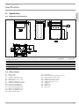
17. Specification ������������������������������������������������ 23
17.1 Dimensions and connections ��������������������������������� 23
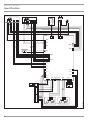
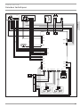
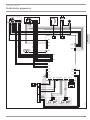
17.2 Wiring diagram ������������������������������������������������� 23
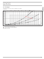
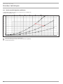
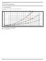
17.3 Fan diagram ����������������������������������������������������� 25
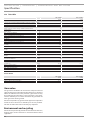
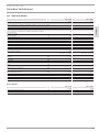
17.4 Data table �������������������������������������������������������� 26
GUARANTEE
ENVIRONMENT AND RECYCLING
SPECIAL INFORMATION
- The appliance may be used by children over 8
years of age and persons with reduced physical,
sensory or mental capabilities or a lack of ex-
perience and expertise, provided that they are
supervised or they have been instructed on how
to use the appliance safely and have understood
the potential risks. Children must never play with
the appliance. Cleaning and user maintenance
must not be carried out by children without
supervision.
- The power cable must only be replaced (for ex-
ample if damaged) by a qualified contractor au-
thorised by the manufacturer, using an original
spare part.
- Fix the appliance in position as described in
chapter "Installation/ Preparations".

OPERATION
General information
www.stiebel-eltron.com VRC-W 400 (E) | 3
ENGLISH
OPERATION
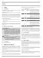
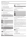
1. General information
The chapters "Special information" and "Operation" are intended
for both users and qualified contractors. The chapter "Installation"
is intended for qualified contractors.
Note
Read these instructions carefully before using the appli-
ance and retain them for future reference. Pass on these
instructions to a new user if required.
1.1 Safety instructions
1.1.1 Structure of safety instructions
!
KEYWORD Type of risk
Here, possible consequences are listed that may result
from failure to observe the safety instructions.
f Steps to prevent the risk are listed.
1.1.2 Symbols, type of risk
Symbol Type of risk
Injury
Electrocution
Burns
(burns, scalding)
1.1.3 Keywords
KEYWORD Meaning
DANGER Failure to observe this information will result in serious
injury or death.
WARNING Failure to observe this information may result in serious
injury or death.
CAUTION Failure to observe this information may result in non-seri-
ous or minor injury.
1.2 Other symbols in this documentation
Note
General information is identified by the adjacent symbol.
f Read these texts carefully.
Symbol Meaning
Material losses
(appliance damage, consequential losses and environmen-
tal pollution)
Appliance disposal
f This symbol indicates that you have to do something. The ac-
tion you need to take is described step by step.
1.3 Information on the unit
Connections
Symbol Meaning
Outdoor air
Exhaust air
Extract air
Supply air
1.4 Standardised output data
Information on determining and interpreting the specified stand-
ardised output data
Standard : EN 13141-7
The output data specifically mentioned in text, diagrams and
technical datasheets has been determined in line with the test
conditions described in the standard shown in the heading of
this chapter.
Generally, these standardised test conditions will not fully meet
the conditions found at the installation site of the system user.
Depending on the chosen test method and the extent to which
the selected method deviates from the conditions described in
the standard shown in the heading of this chapter, any deviations
can have a considerable impact. Additional factors that have an
influence on the test values are the measuring equipment, the
system configuration, the age of the system and the flow rates.
A confirmation of the specified output data can only be obtained
if the conditions applicable to the relevant test match those of the
standard shown in the heading of this chapter.
1.5 Units of measurement
Note
All measurements are given in mm unless stated oth-
erwise.
!
!

OPERATION
Safety
4 | VRC-W 400 (E) www.stiebel-eltron.com
2. Safety
2.1 Intended use
The appliance is designed as a mechanical ventilation unit with
central supply and extract air routing.
The appliance is intended for domestic use. It can be used safely
by untrained persons.
The appliance can also be used in non-domestic environments,
e.g. in small businesses, as long as it is used in the same way. Any
other use beyond that described shall be deemed inappropriate.
Observation of these instructions and of the instructions for any
accessories used is also part of the correct use of this appliance.
It is deemed inappropriate to:
- Use extract air containing grease, explosive gases, dust or
adhesive aerosols
- Connect cooker hoods or vented tumble dryers to the ventila-
tion system
Never adjust the settings of supply and extract air vents inside the
rooms. These have been set up by a qualified contractor during
commissioning.
2.2 General safety instructions
!
WARNING Injury
The appliance may be used by children over 8 years of
age and persons with reduced physical, sensory or men-
tal capabilities or a lack of experience and expertise,
provided that they are supervised or they have been
instructed on how to use the appliance safely and have
understood the potential risks. Children must never play
with the appliance. Cleaning and user maintenance must
not be carried out by children without supervision.
WARNING Injury
The discharged cold air can cause condensation to be
formed in the vicinity of the air discharge.
f Ensure that no risk of slipping due to wet conditions
or ice formation occurs on adjacent footpaths and
driveways at low temperatures.
2.3 Test symbols
See type plate on the appliance.
3. Appliance description
The appliance draws in outdoor air with a fan. A second fan ex-
tracts stale air from the rooms containing odours or moisture,
e.g. kitchen, bathroom, WC. Extract air and outdoor air are routed
through separate air ducts. Extract air and outdoor air are filtered
by separate filters.
The extract air and outdoor air flow through a cross-countercur-
rent heat exchanger. The outdoor air absorbs heat taken from the
extract air. This enables a large proportion of thermal energy to
be recovered.
The air flow rate is preset for each fan stage by the qualified con-
tractor during commissioning. Constant flow rate control ensures
that the air flow rates through the supply air and extract air fans
are achieved irrespective of the duct pressure.
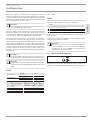
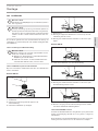
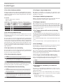
Stage Display
Ventilation
for humidity
protection
0
"Power"
symbol and
digit0
Necessary ventilation for ensuring that
the building structure is protected under
normal conditions of use with somewhat
reduced moisture loads, e.g. during tem-
porary absence of users and no drying of
washing in the residential unit.
Reduced
ventilation
1
"Fan" symbol
and digit1
Reduced ventilation is the ventilation
necessary to meet hygiene standards and
ensure protection of the building structure
(moisture level) under standard conditions
of use with partially reduced moisture and
pollutant loads, e.g. as a result of intermit-
tent user absence.
Standard
ventilation
2
"Fan" symbol
and digit2
Standard ventilation is the ventilation
necessary to meet hygiene standards and
ensure protection of the building structure
when users are present.
Intensive
ventilation
3
“Fan” sym-
bol and
digit3
Intensive ventilation is increased ventila-
tion with a higher flow rate to reduce load
peaks, e.g. for rapid ventilation during or
after a party. You can switch on intensive
ventilation with the "intensive ventilation"
button. Alternatively, you can switch on the
intensive ventilation with an optional ex-
ternally connected switch or button.
VRC-W 400 E : Enthalpy heat exchanger
The enthalpy heat exchanger is a highly efficient, moisture-trans-
ferring countercurrent heat exchanger with a selective membrane.
The membrane helps to recover moisture from the extract air and
transfer it to the supply air. This prevents the relative humidity
in the rooms from dropping too low during the winter months.
3.1 Frost protection
The appliance has a frost protection controller, which ensures that
it works to optimum effect even at low outside temperatures. If the
outdoor air temperature falls below the selected frost protection
value, the electric preheating coil is switched on. This prevents the
cross-countercurrent heat exchanger from freezing up. When the
preheating coil is active, the "frost protection" symbol illuminates
on the display.
3.2 Bypass function
The appliance has an integral bypass damper. The bypass damper
enables the supply of fresh air which does not flow through the
heat exchanger. You can specify the operating mode of the bypass
damper with one parameter on the programming unit (see chapter
"Settings/ Parameters").
Utilising cool outdoor air
Cool, fresh air is required on summer nights in particular. In such
cases, in automatic mode, as much of the warm air in the home
as possible is displaced by cooler fresh air.
Utilising warm outdoor air
In spring and autumn, the appliance can increase the room tem-
perature by opening the bypass damper in automatic mode and
drawing warmer outdoor air into the building.

OPERATION
Settings
www.stiebel-eltron.com VRC-W 400 (E) | 5
ENGLISH
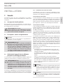
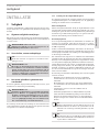
4. Settings
4.1 Switching the appliance on
D0000064394
f Plug the appliance into a standard socket.
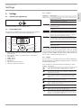
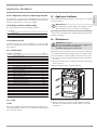
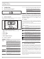
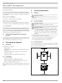
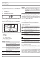
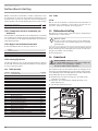
4.2 Programming unit
An external programming unit can be connected to the appliance
in addition to the factory-installed programming unit.
D0000040582
1
4
5
6
7
3
8
2
1 Upper display: Fan stage, parameter number or number of
an actual value
2 Lower display: Values (e.g. temperature or air flow rate)
3 Touch-Wheel
4 "MENU" button
5 "HOME" button
6 "OK" button
7 "Intensive ventilation" button
8 "Intensive ventilation" indicator
4.2.1 Controls
Controls Description
"MENU" button
Press this button for approx. one second to call up the menu
from the standard display.
Within the menu, press this button to return to the beginning
of the menu. Parameter P1 is displayed.
When setting a parameter value, press this button to exit set-
ting of the parameter. Any changes made will not be saved.
"OK" button
In order to set the parameter, you must first make it editable
by pressing the "OK" button. Then you can change the value
with the Touch-Wheel.
Once you have set the parameter, confirm your entry with the
"OK" button.
"HOME" button Calls up the standard display
"Intensive ven-
tilation" button
Use this button to switch the appliance to intensive venti-
lation. You can set the runtime for intensive ventilation in
parameter P2. Once this runtime has expired, the appliance
returns to the previously applicable fan stage.
Touch-Wheel
From the home screen, you can use the Touch-Wheel to
select fan stages 0, 1 and 2, and activate the time programs.
The "time" symbol indicates that time programs are activat-
ed.
Use the Touch-Wheel to select a parameter or value in the
menu.
If you turn the Touch-Wheel quickly, the increment size
changes after a while.
Press the "HOME" and "OK" buttons simultaneously to activate the
function block. The "padlock" symbol appears. Then you can wipe
the programming unit clean without inadvertently changing any
settings. Press the "HOME" and "OK" buttons simultaneously for
two seconds to deactivate the function block.
4.2.2 Display
If no user action occurs within the time selected in the illumination
duration parameter, the display backlighting switches off and the
standard display appears.
Press any button to switch the background lighting on again.
Symbol Description
Power : This symbol indicates that the appliance is switched on
and the fans are operating in "humidity protection" mode.
Time : This symbol indicates that the appliance is operating in time
program mode. Depending on the program, the appliance is oper-
ated at different fan stages.
Fan : This symbol, with the associated digit, indicates the fan
stage at which the appliance is currently running. If the unit has
switched off the fans to prevent condensate, the "Fan" symbol
flashes.
Bypass active : This symbol indicates that the air flow is bypassing
the heat exchanger. No heat is recovered.
This symbol is displayed when the function block is activated.
Press the "HOME" and "OK" buttons simultaneously for two sec-
onds to deactivate the function block.
Filters : Change the filter when this symbol appears.
Frost protection : This symbol is displayed when the appliance has
turned on the preheating coil for frost protection.
Service/fault : The "service/fault" symbol illuminates permanently
in the event of faults that do not impair the basic function of the
appliance. The "service/fault" symbol flashes if a serious fault has
occurred. Call your qualified contractor.

OPERATION
Settings
6 | VRC-W 400 (E) www.stiebel-eltron.com
4.3 Selecting the fan stage
From the home screen, you can use the Touch-Wheel to select fan
stages 0, 1 and 2. The set value is accepted without you having to
press a button to confirm it.
You cannot activate intensive ventilation with the Touch-Wheel.
To switch on intensive ventilation, press the "intensive ventilation"
button for approx. one second. When intensive ventilation is acti-
vated, the "intensive ventilation" indicator illuminates.
You can activate intensive ventilation with an external pushbutton
or with the "intensive ventilation" button. You can only deactivate
intensive ventilation with the "intensive ventilation" button.
4.4 Activating time programs
The "time" symbol indicates that time programs are activated.
If the time programs are not activated, turn the Touch-Wheel
clockwise to switch from the home screen. After fan stage2, the
fan stage set in the time program appears along with the "time"
symbol.
Note
If you switch the appliance to time program operation,
time programs must be entered in the "prog" menu. Oth-
erwise the appliance continues to run without a time limit
in set fan stage 2.
Enter the time program settings in the menu.
At times where there is no time program defined, the appliance
runs in set fan stage 2.
4.5 Menu
Display Description
P1 - Pxx Parameter
I1 - Ixx Actual values
Pro Programs
Cod Entry of the code for unlocking protected parameters and actual
values
f To access the parameters, press the "MENU" button.
The "HOME" button takes you to the standard display. If you have
not changed any settings for a while, the appliance automatically
switches back to the standard display.
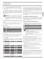
4.5.1 Parameter
Description Options Unit Min. Max. Stand-
ard
P1 Set room temperature °C 5 28 20
P2
This parameter defines
the runtime for inten-
sive ventilation. After
this time has expired,
the appliance returns
to the previously appli-
cable fan stage.
Min.
1
240
30
P3 Bypass mode 0 | 1 | 2 | 3 2
P4 Reset filter 1 | 0
P28 Enable fan On | OFF On
P80 Day 1 7
P81 Time 00:00 23:59
P82 Level of lighting 2 10 10
Description Options Unit Min. Max. Stand-
ard
P83 Mode of backlighting Auto | On | OFF Auto
P84 Illumination duration s 10 500 60
P85
Lower standard display
OFF | Time | Set
room temperature |
Extract air temp. |
Extract air humidity
OFF
In order to set the parameter, you must first make it editable by
pressing the "OK" button. Then you can change the value with
the Touch-Wheel. If you do not press the "OK" button to make the
parameter editable, activating the Touch-Wheel causes the next
parameter to be displayed.
Press the "OK" button to save the set value for a parameter. If you
do not confirm the parameter change with the "OK" button, your
change will be lost.
P1: Set room temperature
Use this parameter to set the outside temperature from which
the bypass damper ensures that outdoor air bypasses the heat
exchanger and flows directly into the building.
P3: Bypass mode
Effect
0 The bypass is permanently disabled. Air flows through the heat exchang-
er.
1 The bypass is active. The air flow bypasses the heat exchanger.
2 The bypass operates with summer day detection. This option is set in the
delivered condition.
3 The bypass operates subject to the extract air temperature.
Note
The qualified contractor can set the parameters men-
tioned in the description of this parameter.
P24: Bypass enable temperature
P25: Bypass blocking temperature
P26: Bypass hysteresis
P27: Temperature differential for enabling the bypass
P3 = 2 : Bypass with summer day detection
For the bypass to be activated, the following condition must apply
for 60 minutes: Outdoor air temperature > Set room temperature
+ P27
If all the following conditions are met, the appliance switches to
bypass mode.
- Outdoor air temperature < Extract air temp. - P26
- Extract air temp. > Set room temperature
If one of the following conditions is met, the appliance terminates
bypass mode.
- Outdoor air temperature < P25
- Outdoor air temperature > Extract air temp. - P26
- Extract air temp. < Set room temperature

OPERATION
Settings
www.stiebel-eltron.com VRC-W 400 (E) | 7
ENGLISH
P3 = 3 : Bypass subject to extract air temperature
For the bypass to be activated, the following condition must apply
for 60 minutes: Extract air temp. > Set room temperature + P27
This delayed enabling prevents cooling down in spring and au-
tumn.
If all the following conditions are met, the appliance switches to
bypass mode.
- Outdoor air temperature < Extract air temp. - P26
- Extract air temp. > Set room temperature
If one of the following conditions is met, the appliance terminates
bypass mode.
- Outdoor air temperature < P25
- Outdoor air temperature > Extract air temp. - P26
- Extract air temp. < Set room temperature
P4: Reset filter
f Set this parameter to 1 after changing the filters. The appli-
ance resets the filter runtime to 0. This parameter is auto-
matically reset to 0.
P28 : Enable fan
You can switch off the fans at any time via the programming unit
menu, e.g. to deactivate ventilation if there is a fire.
Effect
OFF The fans are deactivated. "OFF" and the fan icon flash on the display.
On The fans are enabled.
P80: Day
1 Monday
2 Tuesday
3 Wednesday
4 Thursday
5 Friday
6 Saturday
7 Sunday
P83: Mode of backlighting
Effect
On Backlighting switched on
OFF Backlighting switched off
Auto
If no user action occurs within the time selected in the illumination
duration parameter, the display backlighting switches off and the
standard display appears.
P84: Illumination duration
If no user action occurs within the time selected in the illumination
duration parameter, the display backlighting switches off and the
standard display appears.
P85: Lower standard display
Use this parameter to define what is displayed in the lower section
of the standard display. If the appliance detects a fault, the fault is
indicated in the lower section of the standard display.
4.5.2 Actual values
Display Description Unit
I1 Bypass damper status
I2 Extract air temp. °C
I3 Relative humidity of extract air %
I4 Filter service life h
I5 Appliance software version
I6 Unit software patch
I7 Terminal device serial number
I8 Programming unit software version
I70-79 Fault memory
Faults detected by the appliance are stored in actual values I70 to
I79. The latest fault is stored in I70; the oldest in I79. If no faults
are entered, dashes are shown. The latest fault is also shown in
the lower section of the standard display. Possible faults are listed
for qualified contractors in the "Troubleshooting" chapter.
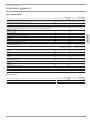
4.5.3 Programs
Pro
The appliance offers the option to set 21 time programs. Switch
between the time programs using the Touch-Wheel. Press the "OK"
button to switch to setting a time program.
Time pro-
gram x
x.1 x.2 x.3 x.4
Day or group of
days
Fan stage Start time Stop time
1
2
3
4
5
6
7
8
9
10
11
12
13
14
15
16
17
18
19
20
21
Setting a time program begins with selecting a day of the week or
a group of days. Press "OK". Set the day using the Touch-Wheel.
Confirm with the "OK" button.

OPERATION
Maintenance, cleaning and care
8 | VRC-W 400 (E) www.stiebel-eltron.com
Use the Touch-Wheel to switch to setting the fan stage. Press
"OK". Set the fan stage in which the appliance runs when the
time program takes effect using the Touch-Wheel. Confirm with
the "OK" button.
Note
You cannot switch on fan stage3 with time programs.
Use the Touch-Wheel to switch to setting the start time. Press
"OK". Set the start time of the respective time program using the
Touch-Wheel. Confirm with the "OK" button.
Use the Touch-Wheel to switch to setting the stop time. Press "OK".
Set the stop time of the respective time program using the Touch-
Wheel. Confirm with the "OK" button. To delete a time program,
go to the menu item where the day or group of days is selected for
the respective time program. Turn the Touch-Wheel anti-clockwise
until the day disappears and dashes appear in the lower section
of the display.
Note
In the case of overlapping time programs, the program
with the highest number takes priority.
Note
At times where there is no time program defined, the
appliance runs in set fan stage 2.
Example
Time scale Stage
Monday - Friday
06:00 - 22:00 2
22:00 - 06:00 1
Saturday , Sunday
07:00 - 23:00 2
23:00 - 07:00 1
x x.1 x.2 x.3 x.4
Day or group of days Fan stage Start
time
Stop time
1 1/2/3/4/5 1 22:00 00:00
2 1/2/3/4/5 1 00:00 06:00
3 6/7 1 23:00 00:00
4 6/7 1 00:00 07:00
4.5.4 Code
Cod
You can use this menu item to enable actual values and parame-
ters, which are reserved for qualified contractors.
Effect
A0 The only parameters displayed are those that have been released for the
appliance user and can therefore be accessed without a code.
A1 Parameters for qualified contractors
A2 Parameters for service department
A1 or A2 is shown on the display when you enter the correct
four-digit code.
If you switch to the actual values or parameters, you see the en-
abled parameters.
Note
After entering the code, switch to the menu by pressing
the "MENU" button. If you first switch to the standard
display by pressing the "HOME" button, the parameter
block is reactivated.
4.6 Switching off the appliance
D0000040280
The appliance has no ON/OFF switch. Disconnect the power supply
by pulling the power plug from its socket.
5. Maintenance, cleaning and care
Maintenance by the user is limited to filter inspection and replace-
ment required at certain intervals.
5.1 Replacement filters
Product
name
Part
number
Description
FMS G4-10 180 234147 Coarse particle filter mat ISO Coarse > 60 % (G4)
FMK M5-2 180 234148 Fine filter ePM
10
≥ 50 % (M5)
FMK F7-2 180 234208 Fine filter ePM
1
≥ 50 % (F7)
5.2 Filter inspection and replacement
!
Material losses
Never operate the appliance without filters.
f Inspect the filters for the first time three months after com-
missioning the appliance.
When the total fan runtimes reach the "Filter change interval"
value, which can be set by the qualified contractor, the program-
ming unit displays the "Filter" symbol.
The qualified contractor can lengthen or shorten the interval for
inspecting filters depending on the level of contamination.
If the "filter" symbol illuminates, check the filters. Change the
filters if the surface is covered completely in dirt or the filter is
discoloured throughout.

OPERATION
Troubleshooting
www.stiebel-eltron.com VRC-W 400 (E) | 9
ENGLISH
Change the filters at least every 12 months.
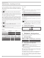
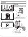
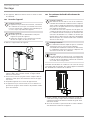
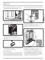
Filter inspection
f Pull the mains plug out of the socket.
3.
2.
1.
D0000040362
1
2
3
4
5
5
1 Extract air filter
2 Outdoor air filter
3 Knurled screw for securing the filter drawer
4 Fascia
5 Locking tabs
The fascia is fastened to the appliance with locking tabs.
f To disengage the locking tabs, press the grip areas on the
fascia sides.
f Remove the fascia from the appliance.
f Undo the knurled screws securing the filter drawer.
f Pull the filter drawer forwards to remove it from the
appliance.
f If necessary, place one or more new filters in the filter
drawer. Ensure that the filters are installed in the intended
position. Air flows through the filters from top to bottom. The
flow direction is indicated with an arrow on the filter drawer
fascia. The outdoor air filter is marked with an arrow. Install
the outdoor air filter with the arrow pointing in the flow
direction. The extract air filter is imprinted with the words
"Clean air side", which must be at the bottom.
!
Material losses
Operate the appliance with at least the recommended
filter class. Ensure that filters are fitted accurately so they
can function properly.
f Push the filter drawer into the appliance.
f Secure the filter drawer with the knurled screws.
f Fit the fascia.
f Plug the mains plug into a standard socket.
f Carry out a filter reset by setting parameter P4 to 1. The
"filter" symbol disappears. The appliance resets the filter
runtime to 0.
f Make a note of the filter change date.
Note
There is a label for each filter on the front panel.
f Once you have performed a filter change, erase the
previously entered dates in the "Last" and "Next"
columns.
f Enter today's date in the "Last" column.
f Enter the date for the next filter change in the "Next"
column. For the period between "Last" and "Next",
use the value set by the qualified contractor in pa-
rameter P19.
f Order new filters in good time or purchase a filter
subscription.
Note
If other filters are installed in the system, e.g. filters in the
extract air vents or a filter box, also perform the inspec-
tion there and change the filter(s) if necessary.
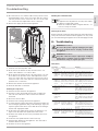
6. Troubleshooting
Faults detected by the appliance are stored in actual values I70
to I79. The latest fault is also shown in the lower section of the
standard display.
If you cannot remedy the fault, contact your qualified contractor.
To facilitate and speed up your request, provide the number from
the type plate (000000-0000-000000).

INSTALLATION
Safety
10 | VRC-W 400 (E) www.stiebel-eltron.com
INSTALLATION
7. Safety
Only a qualified contractor should carry out installation, commis-
sioning, maintenance and repair of the appliance.
7.1 General safety instructions
We guarantee trouble-free function and operational reliability only
if original accessories and spare parts intended for the appliance
are used.
WARNING Electrocution
Do not reach into the interior of the appliance through
the "Outdoor air" connection when the power supply is
switched on.
7.2 Instructions, standards and regulations
Note
Observe all applicable national and regional regulations
and instructions.
!
WARNING Injury
In connection with the fire prevention regulations con-
cerning the installation of ventilation systems, observe
all country-specific regulations and requirements. In
Germany, these are particularly the building regulation
guideline on fire prevention requirements of ventilation
systems in its applicable version.
7.3 Operation of the appliance in buildings with
combustion equipment
The term "combustion equipment" used below includes, for exam-
ple, tiled stoves, fireplaces and equipment with gas combustion.
!
WARNING Injury
Ventilation units can generate negative pressure in the
dwelling. If combustion equipment is operating at the
same time, combustion exhaust gases can penetrate the
room where the combustion equipment is installed. It is
therefore important to observe a number of points for
simultaneous operation of a ventilation unit and com-
bustion equipment.
The engineering, installation and operation of the ventilation unit
and combustion equipment must be carried out in accordance with
national and regional regulations.
7.3.1 Planning safety measures
Together with the relevant authorities, engineers plan the safety
measures that are required for simultaneous operation of a ven-
tilation unit and combustion equipment.
Alternate operation
Alternate operation means that, when the combustion equipment
is started, the mechanical ventilation system is switched off and/
or cannot be started. Alternate operation must be ensured by
appropriate measures, e.g. automatically enforced shutdown of
the ventilation unit.
Simultaneous operation
For simultaneous operation of combustion equipment and a me-
chanical ventilation system, we recommend choosing approved
room sealed combustion equipment (in Germany, with DIBt ap-
proval).
If open flue combustion equipment is operated in the dwelling
at the same time as a ventilation unit, combustion exhaust gases
must be prevented from penetrating the home as a result of pos-
sible negative pressure in the room.
The ventilation unit may only be operated in combination with
intrinsically safe combustion equipment. This combustion equip-
ment has, for example, a draught hood or an exhaust gas monitor
and is permitted to be operated in conjunction with ventilation
units. Alternatively, external, tested safety equipment can be con-
nected to monitor the operation of the combustion equipment.
For example, you can install differential pressure monitoring to
monitor the chimney draught and to switch off the ventilation unit
in the event of a fault.
The equipment for differential pressure monitoring must fulfil the
following requirements:
- Monitoring of the differential pressure between the connec-
tion piece to the chimney and the room where the combus-
tion equipment is installed
- Possibility of matching the shutdown value for the differential
pressure to the minimum draught requirement for the com-
bustion equipment
- Floating contact to switch off ventilation
- Optional connection of a temperature capturing device so
that differential pressure monitoring is only enabled when
the combustion equipment is in operation and so that un-
wanted shutdowns due to environmental influences can be
avoided
Note
Differential pressure switches that use the pressure
differential between the outdoor air pressure and the
pressure in the room where the combustion equipment
is sited as a response criterion are not suitable.
Note
We recommend installing and regularly maintaining a
carbon monoxide detector in accordance with EN50291
for operation of any combustion equipment.

INSTALLATION
Appliance description
www.stiebel-eltron.com VRC-W 400 (E) | 11
ENGLISH
7.3.2 Commissioning
When commissioning the ventilation unit, it is important to check
and document in the commissioning log that combustion exhaust
gases are not penetrating the dwelling in a quantity that is harmful
to health.
Commissioning in Germany
Acceptance is carried out by the local flue gas inspector.
Commissioning outside Germany
Acceptance must be carried out by a specialist. In case of doubt,
you must involve an independent expert in the acceptance pro-
cedure.
7.3.3 Maintenance
Regular maintenance of the combustion equipment is prescribed.
Maintenance includes checking the exhaust gas extraction system,
the free pipe cross-sections and the safety equipment. The rele-
vant qualified contractor responsible must prove that there is a
sufficient flow of combustion air.
7.4 Operating the appliance in passive houses
If operating the appliance in a passive house, the factory-fitted
outdoor air filter must be replaced. See chapter "Appliance de-
scription/ Accessories".
8. Appliance description
8.1 Standard delivery
The following are delivered with the appliance:
- Wall mounting bracket
- 2 star grips as spacers for the rear of the appliance
- Condensate drain hose, hose clip, mounting bend
- 4twin connectors, nominal diameter160
8.2 Accessories
- Programming unit
- Silencer attachment ( LWF SDA 180/280 )
- For installation of the equipment in passive houses: Outdoor
air filter ePM
1
≥ 50 % (F7)
You can obtain ventilation pipes, extract air and supply air vents
and similar accessories from us.
9. Preparation
9.1 Storage
!
Material losses
Never store the appliance in dusty places.
9.2 Installation site
!
Material losses
Never install the appliance outdoors.
!
Material losses
Check whether the wall can bear the weight of the appli-
ance. A plaster board or metal framed wall is inadequate.
Additional measures such as a double skin or additional
supports would be needed in such cases.
- Ensure the appliance is level after installation.
- The installation room must have an adequate condensate
drain with siphon.
- The installation room must be free from the risk of frost.
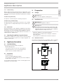
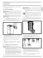
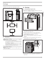
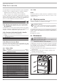
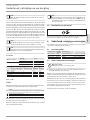
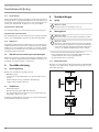
9.2.1 Minimum clearances
If you wish to install the silencer attachment, which is available
as an accessory, observe the minimum clearances it requires.
≥400
≥700
≥400
≥300
≥300
D0000040354

INSTALLATION
Installation
12 | VRC-W 400 (E) www.stiebel-eltron.com
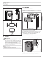
Installation drawing with silencer attachment
1486
1340
147
379
D0000085684
≥100
≥700
≥400
≥400
D0000085683
9.3 Transport
!
Material losses
If possible, transport the appliance to the installation lo-
cation in its original packaging.
If the appliance is transported without packaging and
without using a pallet, e.g. to carry it up or down stairs,
its outer casing may be damaged.
To transport the appliance without packaging, first re-
move the front panel of the appliance. See chapter "In-
stallation/ Removing the front panel".
!
Material losses
Never use the air connections as handles for carrying
the appliance.
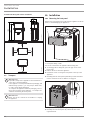
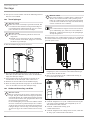
10. Installation
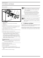
10.1 Removing the front panel
Remove the front panel before removing the appliance from the
pallet, to avoid damaging the appliance.
D0000040363
1
2
2
1 Fascia
2 Front panel fixing screws
The fascia is fastened to the appliance with locking tabs.
f To disengage the locking tabs, press the grip areas on the
fascia sides.
f Remove the fascia from the appliance.
f Undo both screws securing the front panel at the top of the
appliance.
f Carefully push the front panel upwards by a small amount to
release it from the hooks on which it is engaged.
D0000040364
1
1 Plug on cable from programming unit to appliance
f Carefully raise the front panel by a small amount on the
right-hand side.

INSTALLATION
Installation
www.stiebel-eltron.com VRC-W 400 (E) | 13
ENGLISH
f On the appliance, pull out the plug connecting the program-
ming unit with the appliance.
10.2 Mounting the appliance
!
Material losses
If the unit is not mounted horizontally, condensate cannot
drain properly. Condensate escaping in an uncontrolled
manner can damage the floor or items in the vicinity of
the unit.
!
Material losses
f Check whether the wall can bear the weight of the
appliance.
f Use appropriate rawl plugs and screws suitable for
the wall structure to attach the rail.
f Remove the wall mounting bracket from the appliance.
D0000040851
f Secure the wall mounting bracket to the wall with four
screws. The text "TOP" must be at the top. The wall mounting
bracket must be horizontal.
f If necessary, screw the star grips included in the standard
delivery into the back of the appliance at the bottom to act as
spacers.
f Fit the appliance onto the hooks of the wall mounting
bracket.
f If the appliance is not hanging horizontally, screw the previ-
ously fitted star grips acting as spacers in or out by a small
amount.
10.3 Connecting the condensate drain hose
!
Material losses
To ensure that condensate drains correctly, always lay
the condensate drain hose without any kinks. Lay the
condensate drain hose with a fall of at least 10%. Ensure
the appliance is level after installation.
The drain pipe may only contain one siphon. The con-
densate must be able to drain freely downstream of the
siphon. The condensate must drain away via the domestic
sewer system. The pipes must not rise in the domestic
sewer system downstream of the siphon. The condensate
drain must be free from the risk of frost.
!
Material losses
A float switch prevents condensate from reaching live
parts in the unit.
If the condensate drain hose is installed incorrectly, the
float switch cannot prevent the uncontrolled leakage of
condensate.
Note
To ensure the unit is airtight, there may be no inter-
ruption in the condensate drain between the unit and
the trap. Use the supplied condensate drain hose and
mounting bend.
The standard delivery includes a condensate drain hose and a
hose clip. Connect the thinner end of the condensate drain hose
to the appliance.
≥80
D0000058970
f Use the mounting bend included in the standard delivery to
install the condensate drain hose in such a way as to create a
siphon with a water trap height of at least 80mm.
f Before connecting the condensate drain hose to the appli-
ance, pour water into the siphon.
D0000058969
1
1 Hose clip
f Slide the hose clip onto the condensate drain hose far
enough to be able to push the hose onto the condensate
drain connector without squeezing the hose clip.
f Push the condensate drain hose onto the condensate drain
connector.
f Push the hose clip towards the appliance so that it secures
the hose on the condensate drain connector.

INSTALLATION
Installation
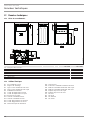
14 | VRC-W 400 (E) www.stiebel-eltron.com
10.4 Air ducts
!
Material losses
Never link cooker hoods to the ventilation system.
!
Material losses
During installation, ensure that no metal swarf enters
the pipework. However, should this occur, remove this
debris, otherwise the fans may be damaged.
Install the air ducts using materials that can be obtained from us
or with commercially available folded spiral-seam tubes.
10.4.1 Insulation against condensation
!
Material losses
When warm air meets cold surfaces, condensation can
result.
f For outdoor air and exhaust air ducts, use vapour
proof thermally insulated pipes.
f If the supply and extract air ducts are routed
through unheated rooms, insulate these ducts as
well.
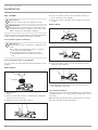
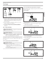
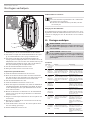
10.4.2 Connecting air ducts to the appliance
You can connect air ducts with two different diameters to the
appliance.
Diameter DN160
D0000062517
1
2
1 Twin connector
2 Air duct
f Push one of the twin connectors included in the standard de-
livery into the air connection.
f Push the air duct onto the twin connector.
3x
3x
1
D0000062518
1 Self-tapping screw
f Use no more than 3 screws to secure the twin connector to
the air connection of the appliance.
f Secure the air duct to the twin connector with no more than
3 screws.
Diameter DN180
D0000062519
f Push the air duct over the air connector.
3x
1
D0000062520
1 Self-tapping screw
f Use no more than 3 screws to secure the air duct to the air
connection of the appliance.
D0000062521
1
1 Aluminium sealing tape
f Seal the transition from the air connection to the air duct
with aluminium sealing tape.
10.4.3 External wall ducts
Install the outdoor air intake into the building at a location where
contamination (dust, soot, odours, flue gas, exhaust air) is as low
as possible.
When installing external wall ducts, prevent any short circuit be-
tween the air intake and the air discharge.

INSTALLATION
Installation
www.stiebel-eltron.com VRC-W 400 (E) | 15
ENGLISH
10.4.4 Silencers
f Install a silencer in both the supply air duct and the extract
air duct. Install these silencers as close as possible to the ap-
pliance, so that noise is suppressed at an early stage.
We recommend installing additional silencers if required to avoid
sound transmission.
If a room with a high noise level needs to be ventilated, install
additional silencers upstream of this room to reduce sound trans-
mission to the neighbouring rooms.
Aspects such as carried voices and impact sound must also be
taken into consideration in the case of ducts embedded in con-
crete. Carried voices should be avoided by designing the duct with
separate branches to the vents. If necessary, insulate the supply air
ducts, e.g. if they are mounted outside the insulated wall panel.
10.4.5 Overflow apertures
Living rooms and bedrooms are only supplied with air. Air is only
extracted from rooms where odours and moisture are generated.
Ensure an unimpeded overflow and consequently air balancing.
Install ventilation grilles in internal doors or walls, or enlarge the
air gap beneath the door to ≥8mm.
10.4.6 Cleaning apertures
f Fit cleaning apertures when installing the air ducts, so
that the air ducts can be inspected and cleaned at regular
intervals.
10.4.7 Supply and extract air vents
Supply and extract air vents for the living space are available for
wall or ceiling mounting.
When venting the kitchen, ensure that the extract air vent is fitted
as far as possible from the cooker.
10.5 Fitting the front panel
f Push the plug on the cable leading to the programming unit
into the appliance.
f Hook the front panel into the hooks provided at the front of
the appliance.
f At the upper edge of the front panel, screw in the two screws
for securing the front panel to the appliance.
f Fit the fascia.
10.6 Electrical connection
WARNING Electrocution
Carry out all electrical connection and installation work
in accordance with national and regional regulations.
Use the plug on the power cable to connect the appliance to a
standard socket.
Take the power consumption of the preheating coil into consid-
eration.
10.6.1 Safety equipment for stove/fireplace operation
f Install the safety equipment in such a way that it interrupts
the appliance power supply when required.
10.6.2 Connections in the control panel ( Safety extra low
voltage )
D0000065179
f Undo the four screws from the control panel cover.
Note
After completing your work, screw the cover back onto
the control panel.
D0000065180
f Carefully lift up the control panel cover. The terminal block,
from which cables lead into the appliance, is suspended from
the underside of the cover.

INSTALLATION
Commissioning
16 | VRC-W 400 (E) www.stiebel-eltron.com
Terminal Safety extra low voltage
1 I²C bus SCL External programming unit
2 SCL
3 GND External programming unit
4 GND
5 +5VDC External programming unit
6 +5VDC
7 SDA External programming unit
8 SDA
9 Not assigned Floating
10
11
12
13 Intensive ventilation switch-
ing contact
GND 0.5mA max.
14 +5 V
15 Not assigned Floating
16
17 Not assigned Floating
To connect an electrical cable in the control panel:
f Open an "entry for electrical cables" at the knock-out.
f Use an M12 cable fitting to seal the "entry for electrical
cables".
Intensive ventilation switching contact
You can connect a floating switching contact, the actuation of
which switches the appliance to intensive ventilation. You can set
the runtime for intensive ventilation in parameter P2. After this
time has expired, the appliance returns to the previously appli-
cable fan stage.
f Connect the external pushbutton to terminals 13/14.
External programming unit
The programming unit is connected with an I²C bus.
11. Commissioning
!
WARNING Injury
If the unit is switched on without the air ducts connected
and someone reaches through the air connectors into the
unit, there is a risk of injury.
Do not commission the unit until the air ducts are firmly
connected to it.
!
Material losses
Never operate the appliance without filters.
!
Material losses
Never operate the ventilation system if there are high lev-
els of dust inside the building or outside in the immediate
vicinity, as this could block the filter. Dust is created by
cutting tiles or working with plasterboard, for example.
11.1 Initial start-up
f To access the parameters, press the “MENU” button.
Display Description
P1 - Pxx Parameter
I1 - Ixx Actual values
Pro Programs
Cod Entry of the code for unlocking protected parameters and actual
values
f Enter 1000 to enable actual values and parameters which are
reserved for qualified contractors.
Enable fan
The fans are deactivated in the delivered condition.
f P28 : Set the parameter to "On".
Setting air flow rates
f Use parameters P6 to P9 to set the air flow rates for the fan
stages.
Date
f Set the current day of the week.
P80 1 Monday
2 Tuesday
3 Wednesday
4 Thursday
5 Friday
6 Saturday
7 Sunday
Time
f Set the current time.
P81 00:00 - 23:59
11.2 Recommissioning
f Check whether filters are fitted in the appliance. Never oper-
ate the appliance without filters.
f Check whether the condensate drain hose is damaged or
kinked.

INSTALLATION
Settings
www.stiebel-eltron.com VRC-W 400 (E) | 17
ENGLISH
12. Settings
When you enter a four-digit code, additional actual values become
visible, which were hidden beforehand.
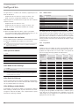
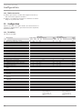
12.1 Parameter
P28: Delivered condition OFF
VRC-W 400 VRC-W 400 E
Description Code Unit Min. Max. Options Stand-
ard
Min. Max. Options Stand-
ard
P1 Set room temperature A0 °C 5 28 20 5 28 20
P2 Intensive ventilation runtime A0 Min. 1 240 30 1 240 30
P3 Bypass mode A0 0 | 1 | 2 | 3 2 0 | 1 | 2 | 3 2
P4 Reset filter A0 0| 1 - 0| 1 -
P6 Flow rate, stage0 A1 m³/h 40 150 60 40 150 60
P7 Flow rate, stage 1 A1 m³/h 60 300 140 60 300 140
P8 Flow rate, stage 2 A1 m³/h 60 400 200 60 400 200
P9 Flow rate, stage 3 A1 m³/h 60 400 260 60 400 260
P14 Supply air flow rate offset A1 -100 100 0 -100 100 0
P15 Humidity protection interval A1 h 1 24 1 1 24 1
P16 Start-up time for humidity measurement A1 min 5 15 5 5 15 5
P17 Extract air humidity limit A1 % 5 95 65 5 95 65
P18 Frost protection temperature A1 °C -10.0 10.0 4.0 -10.0 10.0 4.0
P19 Filter change interval A1 d 1 365 90 1 365 90
P22 Enable preheater A1 0 | 1 1 0 | 1 1
P23 Frost protection mode A1 0 | 2 2 0 | 2 2
P24 Bypass enable temperature A1 °C 5.0 15.0 10.0 5.0 15.0 10.0
P25 Bypass blocking temperature A1 °C 5.0 15.0 8.0 5.0 15.0 8.0
P26 Bypass hysteresis A1 K 0.0 5.0 2.0 0.0 5.0 2.0
P27 Temperature differential for enabling the bypass A1 °C 0.0 5.0 2.0 0.0 5.0 2.0
P28 Enable fan A0 On | OFF On On | OFF On
P29 Appliance type A1 9 10
P30 Temperature for enabling frost protection A2 °C -10.0 10.0 -3.0 -10.0 10.0 -3.0
P31 Enabling of humidity-dependent flow rate control A1 0| 1 0 0| 1 1
P32 Enable outdoor air condensate prevention A2 0 | 1 0 0 | 1 0
P33 Temperature offset for condensate prevention A2 K -5.0 5.0 0.0 -5.0 5.0 0.0
P35 Bypass function cooling/heating A2 1 | 2 | 3 1 1 | 2 | 3 1
P70 Delete fault list A1 0| 1 - 0| 1 -
P80 Day A0 1 7 1 7
P81 Time A0 00:00 23:59 00:00 23:59
P82 Level of lighting A0 2 10 10 2 10 10
P83 Mode of backlighting A0 Auto | On | OFF Auto Auto | On | OFF Auto
P84 Illumination duration A0 s 10 500 60 10 500 60
P85
Lower standard display
A0
OFF | Time | Set room
temperature | Extract
air temp. | Extract air
humidity
OFF
OFF | Time | Set room
temperature | Extract
air temp. | Extract air
humidity
OFF

INSTALLATION
Settings
18 | VRC-W 400 (E) www.stiebel-eltron.com
P14 : Supply air flow rate offset
Use this parameter to adjust the supply air flow rate during com-
missioning. The offset refers to standard ventilation and is con-
verted internally as a percentage for the other fan stages.
Example
- Nominal flow rate (stage2): 180 m³/h
- Offset : 45 m³/h
Stage
Set flow
rate
Off-
set
Set flow
rate +
Offset
Offset fac-
tor
Internal set flow
rate = Set flow rate
* Offset factor
0 50 50*1.25 = 62
1 130 130*1.25 = 162
2 180 45 180+45 = 225 225/180 = 1.25 180*1.25 = 225
3 235 235*1.25 = 294
P15 : Humidity protection interval
If you set fan stage 0, the appliance switches to a 24 hour dormant
phase. The humidity protection control unit only starts after this.
The appliance measures the humidity of the extract air for the time
set in P16. The appliance compares the last measured value with
the limit value set in P17. If the limit value is exceeded, the appli-
ance starts to ventilate. If the limit is undershot again, the appli-
ance terminates ventilation. At this point, the humidity protection
interval restarts, at the end of which the moisture is measured.
P16 : Start-up time for humidity measurement
The appliance measures the humidity of the extract air for the time
set in P16. The appliance compares the last measured value with
the limit value set in P17.
P22 : Enable preheater
Effect
0 The internal preheater is completely deactivated.
1
The internal preheater is activated. In order to keep the heat exchanger
free from ice, the preheater ensures a minimum supply air temperature
with reference to the frost protection temperature adjustable in param-
eter P18.
While this parameter is being displayed or adjusted, the "frost
protection" symbol is shown on the display.
P23 : Frost protection mode
Effect
0 At this setting, the appliance operates solely in frost protection mode. The
preheating coil control only measures the outside temperature.
2
At this setting, the appliance operates in comfort mode. In addition to the
outside temperature, the supply air temperature is also measured. The
preheating coil is controlled to ensure that the supply air temperature
does not fall below the 16.5°C specified in the passive house criteria.
P24 : Bypass enable temperature
To enable checking of the other parameters for the bypass, the
outdoor air temperature must be no less than the value set in
this parameter.
P25 : Bypass blocking temperature
If the outdoor air temperature falls below this blocking tempera-
ture, the bypass is deactivated.
P26 : Bypass hysteresis
To make cooling possible, the outdoor air temperature must be
lower than the extract air temperature by the value set in this
parameter.
To make heating possible, the outdoor air temperature must be
higher than the extract air temperature by the value set in this
parameter.
P27 : Temperature differential for enabling the
bypass
Use this parameter to define the temperature differential that must
be exceeded for the bypass to be enabled. For the bypass to be
enabled, the following condition must be met for 60 minutes.
P3 = 2 : Outdoor air temperature > Set room temperature + P27
P3 = 3 : Extract air temp. > Set room temperature + P27
P29 : Appliance type
This parameter is set at the factory. The parameter can only be set
after the controller assembly has been replaced.
P30 : Temperature for enabling frost protection
The unit only activates frost protection heating if the outdoor air
temperature drops to the value that can be set in this parameter.
P31 : Enabling of humidity-dependent flow rate
control
With humidity-dependent flow rate control, the air flow rate is
increased or decreased depending on the humidity level.
Effect
0 inactive
1 active
P32 : Enable outdoor air condensate prevention
The condensate prevention function is intended for units without
an enthalpy heat exchangers in areas with a subtropical climate.
If the unit is in ventilation mode and this parameter has the value
1, the unit checks the following conditions:
- Outdoor air temperature > Extract air temp.
- Extract air temp. + P33 < Outdoor air dew point
If both conditions are met, the unit switches the fans off. After
a shutdown, the unit switches on the fans cyclically and checks
whether the conditions are still valid or whether ventilation mode
can be resumed.
Interval between measurements min 60
Duration of measurement min 5

INSTALLATION
Appliance shutdown
www.stiebel-eltron.com VRC-W 400 (E) | 19
ENGLISH
P33 : Temperature offset for condensate prevention
This parameter is used to vary the shutdown point for condensate
prevention. This allows the fans to be switched off 2K before the
dew point temperature is reached, for example.
P35 : Bypass function cooling/heating
f Set the operating mode for the bypass function.
Effect
1 Cooling/heating
2 Cooling
3 Heating
P70 : Delete fault list
To delete the fault list, set this parameter to 1. Press the "OK"
button to confirm. Afterwards, 0 is displayed again and the fault
list is deleted.
12.2 Actual values
Display Description Unit
I1 Bypass damper status
I2 Extract air temperature °C
I3 Relative humidity of extract air %
I4 Filter service life h
I5 Appliance software version
I6 Unit software patch
I7 Terminal device serial number
I8 Programming unit software version
I9 Outdoor air temperature °C
I10 Supply air temperature °C
I11 Exhaust air temperature °C
I12 Relative humidity of outdoor air %
I13 Extract air dew point °C
I14 Outdoor air dew point °C
I15 Supply air fan control level %
I16 Calculated supply air flow rate m³/h
I17 Exhaust air fan control level %
I18 Calculated exhaust air flow rate m³/h
I19 Percentage output of internal preheating %
I20 Ventilation unit operating time d
I21 Fan operating time d
I22 Extract air pressure differential Pa
I23 Fan speed, supply air fan rpm
I24 Fan speed, exhaust air fan rpm
I70-79 Fault
12.3 Code
Cod
Enter 1000 to enable actual values and parameters which are re-
served for qualified contractors. "A1" is shown on the display when
this is entered correctly.
13. Appliance shutdown
We recommend running the appliance in fan stage1, even during
prolonged absence.
!
Material losses
If you interrupt the power supply to the appliance, check
that humidity protection is ensured for the building.
If the appliance needs to be taken out of use for an extended peri-
od, disconnect it from the power supply by pulling the mains plug.
f Replace the filters.
14. Maintenance
WARNING Electrocution
Disconnect the appliance from the power supply before
carrying out work inside the appliance.
f Pull the mains plug out of the socket.
Maintenance by the qualified contractor includes cleaning the
cross-countercurrent heat exchanger and the fans. Subject to runt-
ime, this maintenance work should be carried out every 3years.
f Disconnect the power supply by pulling the power plug from
its socket.
f Remove the front panel (see chapter "Installation/ Removing
the front panel").
f Remove the filter drawer from the appliance.
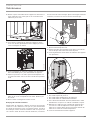
D0000065159
f Undo the screws on the inner front panel.
f Remove the inner front panel from the appliance by tilting
the inner front panel forwards and then lifting it out of the
bottom slots.

INSTALLATION
Maintenance
20 | VRC-W 400 (E) www.stiebel-eltron.com
D0000082556
1
1 Wing screw
f To remove the heat exchanger from the appliance, undo the
wing screw, which pushes the support bar against the heat
exchanger from below.
D0000040365
f Carefully remove the heat exchanger from the unit. Avoid
damaging the gaskets in the appliance.
f Use a commercially available vacuum cleaner to remove dust
and other loose dirt particles from the intake and discharge
surfaces.
26�04�15�0047
f If required, clean the heat exchanger with warm water
(max.55 °C) and a commercially available detergent. Do not
use solvents.
f Flush the heat exchanger with water.
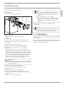
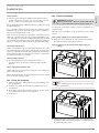
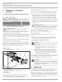
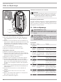
Cleaning the fan units
Each fan unit has a rotating eccentric bolt at the bottom. To ensure
that the seals fit correctly on the fan unit, the eccentric bolt raises
the fan unit while pushing it towards the back. Release the eccen-
tric bolt before pulling out the fan unit. Retighten the eccentric
bolt after installing the fan unit.
300°
D0000063652
1
2
1 Eccentric bolt tightened (slot horizontal)
2 Eccentric bolt released
f Use a medium sized screwdriver to turn the eccentric bolt
anti-clockwise by 300°.
f Carefully pull both fan units from the appliance by a small
amount.
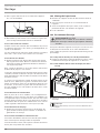
D0000040366
4
3
1
2
1 Temperature sensor connection
2 Pressure sensor connection
3 Connection for the fan power cable
4 Connection for the fan control cable
f At the front of the supply air fan, disconnect the 3-core power
cable and the 4-core control cable.
Page is loading ...
Page is loading ...
Page is loading ...
Page is loading ...
Page is loading ...
Page is loading ...
Page is loading ...
Page is loading ...
Page is loading ...
Page is loading ...
Page is loading ...
Page is loading ...
Page is loading ...
Page is loading ...
Page is loading ...
Page is loading ...
Page is loading ...
Page is loading ...
Page is loading ...
Page is loading ...
Page is loading ...
Page is loading ...
Page is loading ...
Page is loading ...
Page is loading ...
Page is loading ...
Page is loading ...
Page is loading ...
Page is loading ...
Page is loading ...
Page is loading ...
Page is loading ...
Page is loading ...
Page is loading ...
Page is loading ...
Page is loading ...
Page is loading ...
Page is loading ...
Page is loading ...
Page is loading ...
Page is loading ...
Page is loading ...
Page is loading ...
Page is loading ...
Page is loading ...
Page is loading ...
Page is loading ...
Page is loading ...
Page is loading ...
Page is loading ...
Page is loading ...
Page is loading ...
Page is loading ...
Page is loading ...
Page is loading ...
Page is loading ...
Page is loading ...
Page is loading ...
Page is loading ...
Page is loading ...
-
 1
1
-
 2
2
-
 3
3
-
 4
4
-
 5
5
-
 6
6
-
 7
7
-
 8
8
-
 9
9
-
 10
10
-
 11
11
-
 12
12
-
 13
13
-
 14
14
-
 15
15
-
 16
16
-
 17
17
-
 18
18
-
 19
19
-
 20
20
-
 21
21
-
 22
22
-
 23
23
-
 24
24
-
 25
25
-
 26
26
-
 27
27
-
 28
28
-
 29
29
-
 30
30
-
 31
31
-
 32
32
-
 33
33
-
 34
34
-
 35
35
-
 36
36
-
 37
37
-
 38
38
-
 39
39
-
 40
40
-
 41
41
-
 42
42
-
 43
43
-
 44
44
-
 45
45
-
 46
46
-
 47
47
-
 48
48
-
 49
49
-
 50
50
-
 51
51
-
 52
52
-
 53
53
-
 54
54
-
 55
55
-
 56
56
-
 57
57
-
 58
58
-
 59
59
-
 60
60
-
 61
61
-
 62
62
-
 63
63
-
 64
64
-
 65
65
-
 66
66
-
 67
67
-
 68
68
-
 69
69
-
 70
70
-
 71
71
-
 72
72
-
 73
73
-
 74
74
-
 75
75
-
 76
76
-
 77
77
-
 78
78
-
 79
79
-
 80
80


STIEBEL ELTRON VRC-W 400 (E) Operation Instruction
- Type
- Operation Instruction
Ask a question and I''ll find the answer in the document
Finding information in a document is now easier with AI
in other languages
- français: STIEBEL ELTRON VRC-W 400 (E)
- Nederlands: STIEBEL ELTRON VRC-W 400 (E)
Related papers
-
STIEBEL ELTRON LWZ 180 Operation Instruction
-
STIEBEL ELTRON LWZ 180/280 (Enthalpie) Operation Instruction
-
-
-
-
-
-
-
-
Other documents
-
Xpelair Natural Air 180 Vertical User manual
-
Domo DO191A Owner's manual
-
Warm Tech WTCME1000DFO Owner's manual
-
Groen VRC-3E Operating instructions
-
Vinten VRC Installation Operator Guide
-
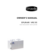 Epurair VRC-95 Owner's manual
-
RADSON vido Operating instructions
-
Barco Trace Installation guide
-
-
