Troubleshooting Chart
Symptom Problem Solution
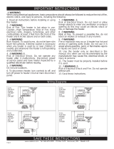
MAINTAINING YOUR HEATER
WARNING! Before removing grill, turn the electrical power off at the main disconnect
panel (circuit breaker or fuse box). Lock or tag the main disconnect panel door to prevent
someone from accidentally turning the power on while you are working on the heater.
Failure to do so could result in serious electrical shock, burns, or possible death.
WARNING: Any other service not detailed in this Owner’s Guide should be performed by an
authorized service representative.
*CONSULT LOCAL ELECTRICAL CODES TO DETERMINE WHAT WORK MUST BE PERFORMED BY QUALIFIED
ELECTRICAL SERVICE PERSONNEL.
Breaker trips
immediately
upon energizing
heater.
1. Incorrect supply voltage.*
2. Overloaded circuit.*
3. A short circuit exists in the supply or
heater wiring.*
4. Defective circuit breaker.*
1. Verify that supply voltage matches the heater rating.
2. The total amperage of all heaters on a branch circuit must not be more than
80% of the amperage rating of the circuit breaker and supply wire ratings. Use a
lower wattage heater, or reduce the number of heaters on the circuit.
3. Shorted supply or heater wires may be accompanied by severe sparking. In-
spect all supply and heater wiring insulation for damage. Do not reset the circuit
breaker until all electrical shorts have been repaired.
4. Replace the circuit breaker.
Heater fan op-
erates, but does
not discharge
warm air.
1. Insufcient element temperature.
2. Incorrect supply voltage.*
3. Element has failed.*
1. Allow a few moments for element to reach operating temperature.
2. Verify that supply voltage matches the heater rating.
3. Replace element.
Heater will not
shut off.
1. Heat loss from room is greater than
heater capacity.*
2. Defective thermostat.
3. Thermostat wired incorrectly to
heater.*
1. Close doors and windows. Provide additional insulation, or install a higher
wattage heater or multiple heaters if necessary. (If your circuit is rated for more
capacity.)
2. Adjust thermostat to its lowest setting. If heater continues to run (allow two
minutes for the thermostat to respond), and room temperature is greater than
50˚, replace the thermostat.
3. Refer to thermostat documentation and correct wiring.
Heater dis-
charges smoke
or emits a burnt
odor.
1. Dust, lint or other matter has
accumulated inside heater.
2. Poor or loose electrical connections.
1. Clean heater (see “MAINTAINING YOUR HEATER” section above for instruc-
tions).
2. Turn off power at circuit breaker. Inspect all supply and heater wire connec-
tions to make sure nothing is loose or poorly connected. Secure or reconnect all
loose connections. Do not reset circuit breaker until all connections have been
checked and repaired.
Element heats
for a moment
without the fan
turning, then im-
mediately stops
heating.
1. Defective motor or internal
connection.*
2. Fan or motor jammed.
1. Heater or fan motor requires replacement.
2. Remove obstruction and press heater manual reset button (see “OPERATING
INSTRUCTIONS” section).
Heater does not
run.
1. Thermostat set too low.
2. Heater has tripped the manual reset
temperature limit control.
3. Power not on at the circuit breaker.
4. Broken or poorly connected wire(s)
to heater.
5. Defective thermostat.
1. Adjust thermostat to a higher temperature until heater operates (see Problem
#5 if the problem persists).
2. Press the manual reset button (see “OPERATING INSTRUCTIONS” section).
3. Turn on the correct circuit breaker in the main disconnect panel.
4. Turn off power at circuit breaker. Check supply wire continuity and proper
connection to heater wires.
5. The entire heater, or any of its components may be checked for continuity to
determine the cause of any problems. Repair or replace the heater or thermo-
stat.
Heater contin-
ually trips the
manual reset
temperature
limit control.
1. Dust, lint or other matter has accu-
mulated inside heater.
2. Airow is blocked.
3. Fan or motor is jammed.
4. None of the above.
1. Clean heater (see “MAINTAINING YOUR HEATER” section for instructions).
2. Remove obstruction. Maintain a minimum distance of 6 inches from adjacent
surfaces, 10 inches from ceiling, 72 inches from the oor, and 3 feet from furni-
ture or other objects placed directly in front of the heater.
3. Remove obstruction, and press heater manual reset button (see “OPERATING
INSTRUCTIONS” section).
4. Replace heater assembly.
Maintenance As Needed, or every 24 months minimum.
1. It is important that you verify the circuit breaker has been turned
off and no power is going to the heater before proceeding. Cir-
cuit breakers are often not marked correctly and turning the wrong
breaker off could mean electricity is owing to the heater, even if
the heater does not appear to be working. If you are uncomfortable
working with electrical appliances, unable to follow these guide-
lines, or do not have the necessary equipment, consult a qualied
electrician.
2. Once you verify the power has been turned off correctly, pro-
ceed to the next step.
3. Allow heater to cool before servicing.
4. Remove decorative cover.
5. Wash decorative cover with hot soapy water and dry.
6. Use a hair dryer, or vacuum on blow cycle, to blow debris
through the outlet grill.
7. Vacuum fan area.
8. Do not lubricate motor.
9. Replace decorative cover.
10. Turn thermostat to desired setting.
11. Turn power back on at the main disconnect panel.
©2015 Cadet Printed in USA Rev 07/15 #730056
Page 5