GPS iDETECT-P Commercial and Industrial HVAC Systems User manual

Type
User manual

GPS iDETECT-P Commercial and Industrial HVAC Systems is a revolutionary ionization detector designed to confirm the output of the GPS-iMOD System, ensuring optimal air purification performance. With its universal voltage input range of 18-260VAC, it seamlessly integrates into various power systems. The device features a compact design with a 1" diameter and 10" length, making it easy to install in tight spaces. The included 1" coated pipe clamp allows for secure mounting to the GPS-iMOD bar.

GPS iDETECT-P Commercial and Industrial HVAC Systems is a revolutionary ionization detector designed to confirm the output of the GPS-iMOD System, ensuring optimal air purification performance. With its universal voltage input range of 18-260VAC, it seamlessly integrates into various power systems. The device features a compact design with a 1" diameter and 10" length, making it easy to install in tight spaces. The included 1" coated pipe clamp allows for secure mounting to the GPS-iMOD bar.

www.globalplasmasolutions.com
Installation, Operation & Maintenance Manual
GPS-iDETECT-P
www.globalplasmasolutions.com
www.gpsair.com
For technical product queries, please reach out to [email protected]
Thank you for purchasing a GPS-iDETECT-P™ from GPS Air. The
GPS-iDETECT-P is a revolutionary product in the air purication industry. The GPS-iDETECT-P is
a plenum mounted ionization detector that conrms the output from the GPS-iMOD® System.
Specications
Voltage Input: 18-260VAC Universal Range
Power Required: 5VA Detecting, 2VA Standby (non-detecting)
Alarm Contact: 24-220VAC, 0.5A relay with NO, NC and C terminals
Dimensions: 1” diameter and 10” long
Wiring Required: 300V, 18/4, plenum rated, SHIELDED, solid strand – provided and installed by others
LED Status: Power On – Green LED, Detecting – Blue LED, both are seen from end opposite power entry
Mechanical Installation
Mount the GPS-iDETECT-P to the GPS-iMOD bar using the included 1” coated pipe clamp and
secure it to a GPS-iMOD section using a nut and bolt as shown in FIGURE 1. The sensor should
be as close as possible to the ionization source.
Wiring Diagram Figure 1
Power On - Green LED
Ion Sensing - Blue LED
Figure 2
www.globalplasmasolutions.com
www.gpsair.com
Power Source
The GPS-iDETECT-P can be connected to either (I) house power source, or (II) GPS-iMOD power
supply. Please reference below the instructions for connecting to the target power source.
I. Wiring direct to house power source
1. Remove cable gland. Remove foam ller, but don’t discard. See FIGURE 2.
2. Use 300V 18/4 plenum-rated, SHIELDED cable rated for the voltage applied. Follow all
local and national electric codes. Solid copper wiring is preferred.
3. The shield on the 18/4 cable should be grounded on one end, opposite the sensor. The
shield on the 18/4 cable inside the sensor should not be connected to anything, including ground!
4. Connect power to the appropriate power input pins of the terminal block. See FIGURE 2. The neutral must be
landed on the N terminal. If 240V, L2 is connected to N terminal.
5. Pull the cable through the gland. Place foam ller over the cable and then terminate to the circuit board. Push the
board and foam spacer into the tube. Tighten the cable gland.
Connection to BMS/BAS
The detector is supplied with an alarm relay that can be wired into the building management system. The internal relay has
been provided with both normally open (NO) and normally closed (NC) connections along with the common (COM) terminal.
See FIGURE 2 for connection details.
The relay will energize once the ion detection threshold has been exceeded proving ion output is present. The relay will
change state once the unit is detecting. There is a 12 second delay after ion detection has ceased to prevent cycling.
I. Wiring direct to GPS-iMOD power supply
1. Remove cable gland. Remove foam ller, but don’t discard. See FIGURE 2.
2. See FIGURE 2 for connections to GPS-iDETECT-P.
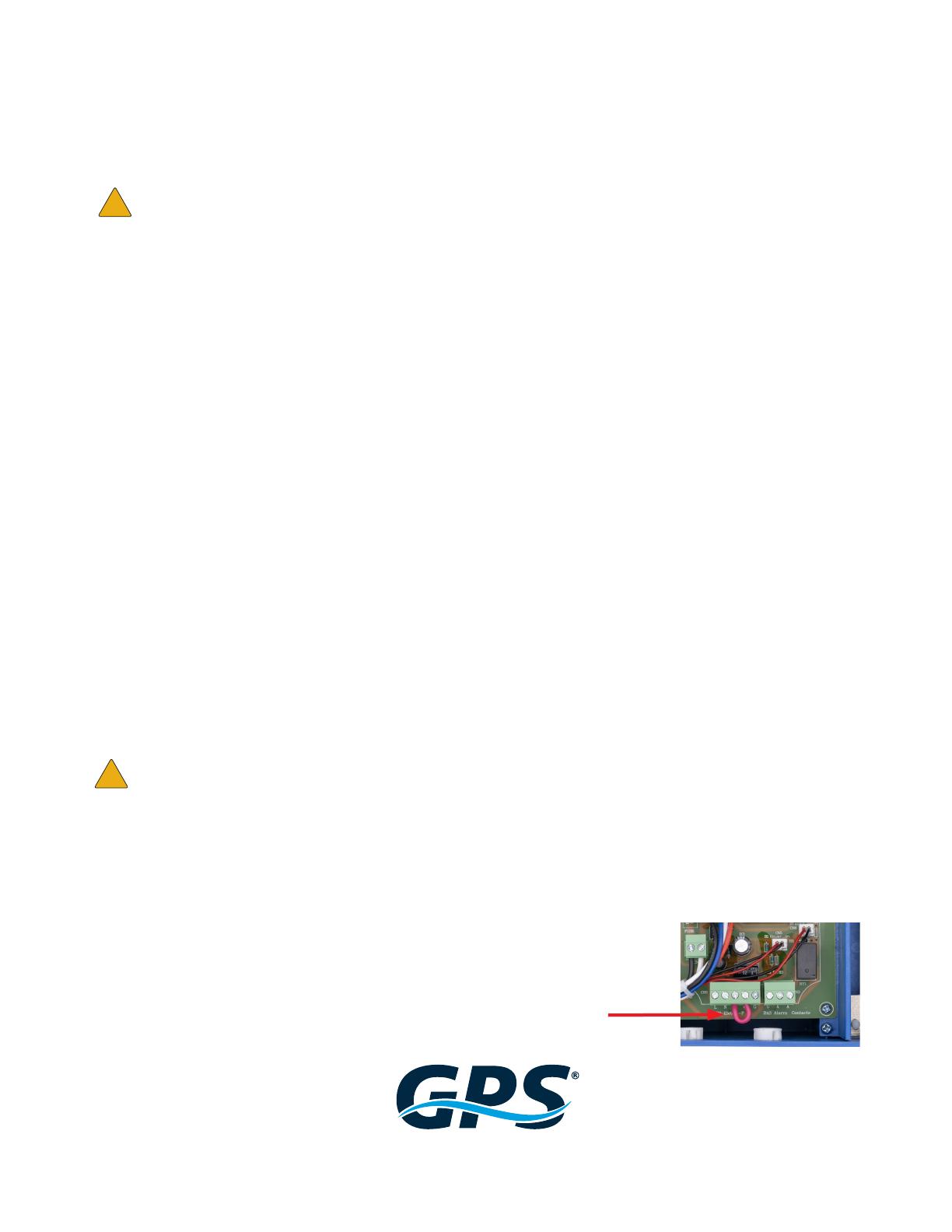
3. Remove the red jumper wire between C and NO on the “GPS-iDetect-P” terminal block inside the GPS-iMOD
power supply (see FIGURE 3 for jumper wire).
4. Use 300V, 18/4, plenum rated, SHIELDED cable wire between the GPS-iDETECT-P terminal block and the GPS-
iMOD power supply “GPS-iDetect-P” terminal block.
5. Connect the line (L), neutral (N), and common wires (COM or C). See FIGURE 4.
6. Connect the normal open (NO) contact on the GPS-iDETECT-P to the “ON” contact on the GPS-iMOD power
supply terminal block (see FIGURE 4).
7. Ground 18/4 SHIELD to the ground contact (G) on the “GPS-iDetect-P” terminal (ref. FIGURE 4).
Only ground ONE end of the shielded cable.
Do not ground the end connected to the GPS-iDETECT-P sensor.
DO NOT RUN CONTROL WIRING WITH HV CABLES!
8. Pull the cable through the gland. Place foam ller over the cable and then terminate to the circuit board. Push the
board and foam spacer into the tube. Tighten the cable gland.
9. When the GPS-iDETECT-P senses output, the “Plasma On” light will illuminate on the front panel of the power
supply and the BAS/BMS Alarm Contacts will close. When using the GPS-iDETECT-P in conjunction with the GPS-
iMOD power supply, always connect to the BMS/BAS using the “BAS Alarm Contacts”
on the GPS-iMOD power supply, and not directly to the contacts
on the GPS-iDETECT-P.
!
!
Figure 3
Jumper Wire
www.globalplasmasolutions.com
www.gpsair.com
Connection to BMS/BAS thru GPS-iMOD Power Supply
Refer to FIGURE 5.
Integral alarm “dry” contacts will close when the system is on and operating properly. To tie into the BMS/BAS for remote
monitoring, use 18/2 twisted pair, SHIELDED, plenum rated cable and connect to the “BAS Alarm” contact terminals inside the
GPS-iMOD power supply. Connect the cable shield to the “BAS Alarm” ground contact (G) shown in FIGURE 5. The
terminal block may be removed for ease of wiring.
Keep the control wiring as far from the HV wiring as possible.
DO NOT RUN BOTH CABLES TOGETHER AND DO NOT ZIP TIE CONTROL WIRING TO
FLEXIBLE HV CABLES!
Product Registration
By registering your order, the standard limited warranty on eligible products from your purchase
is automatically extended to 3 years, at no additional cost.
Register your products at www.gpsair.com/product-registration or scan the QR code.
The information provided in this manual is up to date at the time of printing.
Any revisions to this document will supersede the content included. For the latest
applicable version of this manual, visit our website or utilize the QR code.
!
Figure 4 Figure 5
www.globalplasmasolutions.com
www.gpsair.com
© 2022 GPS Air
GPS Air is the owner of certain trademarks that appear in our materials. Please visit www.gpsair.com/trademarks for a list of our marks.
GPS-041-19-R21-iDP IOM
3101 Yorkmont Road • Suite 400
Charlotte, NC 28208
980-279-5622
To access a list of applicable patents,
please visit www.gpspatents.com
  • Page 1 1
  • Page 2 2
  • Page 3 3
  • Page 4 4
  • Page 5 5

GPS iDETECT-P Commercial and Industrial HVAC Systems User manual

Type
User manual

GPS iDETECT-P Commercial and Industrial HVAC Systems is a revolutionary ionization detector designed to confirm the output of the GPS-iMOD System, ensuring optimal air purification performance. With its universal voltage input range of 18-260VAC, it seamlessly integrates into various power systems. The device features a compact design with a 1" diameter and 10" length, making it easy to install in tight spaces. The included 1" coated pipe clamp allows for secure mounting to the GPS-iMOD bar.

Ask a question and I''ll find the answer in the document

Finding information in a document is now easier with AI