
36
FOR HELP OR ADVICE ON THIS PRODUCT PLEASE CONTACT YOUR DISTRIBU-
TOR, OR SIP DIRECTLY ON:
TEL: 01509500400
EMAIL: sales@sip-group.com or technical@sip-group.com
www.sip-group.com
Ref: 09AUG2021
Please dispose of packaging for the product in a responsible
manner. It is suitable for recycling. Help to protect the
environment, take the packaging to the local amenity tip and
place into the appropriate recycling bin.
Never dispose of electrical equipment or batteries in with your
domestic waste. If your supplier offers a disposal facility please
use it or alternatively use a recognised re-cycling agent. This
will allow the recycling of raw materials and help protect the
environment.
1
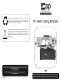
18” Metal Cutting Bandsaw
Please read and fully understand the instructions in this manual
before operation. Keep this manual safe for future reference.
01597

2
35
Declaration of Conformity
We
SIP (Machinery Europe) Ltd
ASM Chartered Accountants
First Floor Block One
Quayside Business Park
Dundalk
County Louth
Republic of Ireland
As the manufacturer's authorised representative within the EC
declare that the
18” Metal Cutting Bandsaw 3ph - SIP Pt. No. 01597
Conforms to the requirements of the following directive(s), as indicated.
2006/42/EC Machinery Directive
2006/95/EC Low Voltage Directive
2004/108/EC EMC Directive
2011/65/EU & (EU)2015/863
RoHS Directive
Signed: …………………………………...
Mr P. Ippaso - Managing Director - SIP (Industrial Products) Ltd
Date: 09/08/2021.
EU - DECLARATION OF CONFORMITY
And the relevant harmonised standard(s), including
EN 55014-1:2017+A11
EN 55014-2:2015
EN IEC 61000-3-2:2019
EN 61000-3-3:2013+A1

34
3
CONTENTS
Page No. Description
4. Safety Symbols Used Throughout This Manual
4. Safety Instructions
8. Electrical Connection
9. Guarantee
10. Technical Specifications
10. Contents & Accessories
11. Getting to Know Your Bandsaw
13. Assembly Instructions
14. Operating Instructions
20. Maintenance Instructions
25. Troubleshooting
26. Exploded Diagram - Left Side Of The Bow
27. Exploded Drawing - Right Side Of The Bow
28. Exploded Drawing - Base
29. Parts List
34.
UK Declaration of Conformity
35.
EU Declaration of Conformity
Declaration of Conformity
We
SIP (Industrial Products) Ltd
Gelders Hall Road
Shepshed
Loughborough
Leicestershire
LE12 9NH
England
As the manufacturer within the UK, England, Scotland & Wales, declare
that the
18" Metal Cutting Bandsaw 3ph - SIP Code 01597
Conforms to the requirements of the following directive(s), as
indicated.
Supply of Machinery (Safety) Regulations 2008
Electrical Equipment (Safety) Regulations 2016
Electromagnetic Compatibility Regulations 2016
The Restriction of the Use of Certain Hazardous Substances in Electrical
and Electronic Equipment Regulations 2012
Signed: …………………………………...
Mr P. Ippaso - Director - SIP (Industrial Products) Ltd
Date: 09/08/2021
And the relevant harmonised standard(s), including
UK - DECLARATION OF CONFORMITY
EN 55014-1:2017+A11
EN 55014-2:2015
EN IEC 61000-3-2:2019
EN 61000-3-3:2013+A1

4
SAFETY SYMBOLS USED THROUGHOUT THIS MANUAL
Danger / Caution: Indicates risk of personal injury and/or the possibility of
damage.
Warning: Risk of electrical injury or damage!
Note: Supplementary information.
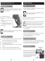
SAFETY INSTRUCTIONS
When using your bandsaw, basic safety precautions should always be followed to re-
duce the risk of personal injury and / or damage to the bandsaw.
Read all of these instructions before operating the bandsaw and save this user manu-
al for future reference.
The bandsaw should not be modified or used for any application other than that for
which it was designed.
Do not use this bandsaw for anything other than its intended purpose; this bandsaw is
designed for metal cutting work in engineering workshops, garages, metal fabricators,
etc.
If you are unsure of its relative applications do not hesitate to contact us and we will
be more than happy to advise you.
Before operating the bandsaw always check no parts are broken, and that no parts
are missing.
Always operate the bandsaw safely and correctly.
KNOW YOUR BANDSAW: Read and understand the owner's manual and labels affixed
to the bandsaw. Learn its applications and limitations, as well as the potential hazards
specific to it.
KEEP CHILDREN AND UNTRAINED PERSONNEL AWAY FROM THE WORK AREA: All visitors
should be kept at a safe distance from the work area; never allow untrained persons
to operate the bandsaw.
STAY ALERT: Always watch what you are doing and use common sense.
NEVER LEAVE THE BANDSAW UNATTENDED: When in use, or connected to the mains
IMPORTANT: Please read the following instructions carefully, failure to do
so could lead to serious personal injury and / or damage to the band-
saw.
33
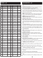
PARTS LIST….cont
Ref. No. Description SIP Part No. Ref. No. Description SIP Part No.
213. Hose WK04-00314 N/A Contactor CN6 WK04-00150
214. Coolant tank WK04-00020 N/A Thermal relay 2.4-3.6A WK04-00152
N/A QF1 Breaker WK04-00147 N/A Transformer WK04-00153
N/A QF2 Breaker WK04-00148 N/A Blade guard microswitch WK04-00154
N/A QF3 Breaker WK04-00149

32
PARTS LIST….cont
Ref. No. Description SIP Part No. Ref. No. Description SIP Part No.
159. Washer M10 WK04-00046 187. Bolt M6x12 WK04-00038
160. Fixed vice jaw WK04-00279 188. Washer M6 WK04-00011
161. Bolt M12x70 WK04-00280 189. Shaft WK04-00300
162. Nut M12 WK04-00173 190. Switch WK04-00301
163. Bolt M12x35 WK04-00282 191. Nut M8 WK04-00015
164. Washer M12 WK04-00049 192. Bolt M8x30 WK04-00018
165. Bushing WK04-00283 193. Panel WK04-00302
166. Movable vice jaw WK04-00284 194. Bolt M5x15 WK04-00303
167. Bolt M10x30 WK04-00285 195. End cover WK04-00304
168. Press plate WK04-00286 196. Connecting beam WK04-00305
169. Pivot arm WK04-00287 196.1. Protector WK04-00306
170. Bolt M8x25 WK04-00137 197. Protect cover WK04-00307
171. Washer M8 WK04-00014 198. Washer M8 WK04-00014
172. Cover plate WK04-00288 199. Bolt M8x20 WK04-00068
173. Nut M24x1.5 WK04-00289 200. Bolt M4x16 WK04-00308
174. Washer WK04-00290 200.1. Mains lead WK04-00309
175. Position set bracket WK04-00291 201. Control box WK04-00310
176. Nut M10 WK04-00052 202. Stand WK04-00311
177. Screw WK04-00292 203. Bolt M8x30 WK04-00018
178. Bolt M10x35 WK04-00045 204. Washer M8 WK04-00014
179. Shaft WK04-00293 205. Nut M8 WK04-00015
180. Bearing WK04-00294 206. Bolt M8x30 WK04-00018
181. Washer WK04-00295 207. Washer M8 WK04-00014
182. Bracket WK04-00296 208. Nut M8 WK04-00015
183. Bolt M8x40 WK04-00132 209. Cover WK04-00312
184. Cut off stop shaft WK04-00297 210. Washer M6 WK04-00011
185. Cut off stop WK04-00298 211. Bolt M6x20 WK04-00016
186. Ring WK04-00299 212. Coolant pump 3ph WK04-00313
5
SAFETY INSTRUCTIONS….cont
supply.
KEEP WORK AREA CLEAN AND WELL LIT: Cluttered work areas and dark areas invite ac-
cidents. Floors must not be slippery due to oil, water or sawdust etc.
HAVE YOUR BANDSAW REPAIRED BY A QUALIFIED PERSON: The bandsaw is in accord-
ance with the relevant safety requirements. Repairs should only be carried out by
qualified persons using original spare parts, otherwise this may result in considerable
danger to the user and void the warranty.
DANGER! Check that the bandsaw is in sound condition and good working order be-
fore each use; Take immediate action to repair or replace faulty / damaged parts.
WARNING! Only operate on a level and stable surface.
WARNING! RISK OF ELECTRIC SHOCK. Do not expose the bandsaw to water spray, rain,
dripping water or moisture of any kind.
PROTECT YOURSELF FROM ELECTRIC SHOCK: When working with machinery, avoid
contact with any earthed items (e.g. pipes, radiators, hobs and refrigerators, etc.). It is
advisable wherever possible to use an RCD (residual current device) at the supply
socket.
DO NOT ABUSE THE MAINS LEAD: Never pull the mains lead to remove the plug from
the mains socket, or to move the bandsaw from place to place. Keep the mains lead
away from heat, oil and sharp edges. If the mains lead is damaged, it must be re-
placed by the manufacturer or its service agent or a similarly qualified person in order
to avoid unwanted hazards.
ALWAYS check that the belt guard and blade guards are in place, adjusted correctly,
undamaged and firmly attached.
NEVER STAND ON THE BANDSAW: The bandsaw is not designed for this purpose.
DO NOT dismantle, tamper with or modify the bandsaw, as this may be dangerous
and will invalidate the warranty.
SECURE THE WORK-PIECE: Use the vice to hold the work-piece; this frees up both
hands to operate the saw.
REMOVE ADJUSTING KEYS AND WRENCHES: Form a habit of checking to see that keys
and adjusting tools are removed from the bandsaw before every use.
If a problem with the bandsaw is experienced or suspected stop using the bandsaw
immediately and contact your distributor for repair.
Regularly inspect the bandsaw, ensuring that it is in good working order and condi-
tion.
Always ensure that the work area is clean, tidy and free from unrelated materials.
Keep away from flammable objects, materials & surfaces, use in a location where
accidental contact (particularly by children) is unlikely.
Ensure on/off switches are switched to off (0) before connecting mains lead to the
power supply.
Keep the work area clean and clear of possible tripping hazards.
Keep children and unauthorised persons away from the bandsaw, as it has a sharp
blade!
Disconnect from the mains before moving or attempting any cleaning or mainte-

6
SAFETY INSTRUCTIONS….cont
nance.
Keep hands and all other body parts away from the blade.
Failure to follow the warnings in this manual, may result in personal injury and/or
property damage.
Turn the bandsaw off and disconnect it from the mains supply when moving from
one location to another.
Never operate the bandsaw without all guards in place.
DO NOT get the bandsaw wet or use in damp or wet locations or areas where there
is condensation.
DO NOT move the bandsaw whilst in operation.
DO NOT remove the blade guard or belt guard whilst the bandsaw is switched on.
DO NOT allow unqualified persons to disassemble the bandsaw for any reason, the
bandsaw must be checked by qualified personnel only.
DO NOT use the bandsaw without the blade guard and belt guard closed, as this
will lead to personal injury to you or others!
WARNING if a fuse blows, ensure it is replaced with the correct fuse type and rating.
DO NOT place any objects on the safety guard or on the covers at any time.
When not in use, store the bandsaw carefully in a safe, dry, childproof location.
NEVER cover the bandsaw during operation or whilst it cools after operation.
Be aware of moving parts that occur during normal operation of this bandsaw.
NEVER operate the bandsaw with damaged, broken or missing parts, or with any
guards or covers removed.
DO NOT operate the bandsaw or any electrical items with wet hands.
Keep the floor around the machine clean and free of scrap material, oil and
grease.
ALWAYS keep the machine guards in place at all times when the machine is in oper-
ation, if removed for maintenance then use extreme caution, always refit the guards
immediately after any maintenance.
DO NOT over reach, always maintain a balanced stance so that you do not fall or
lean into any moving parts.
Keep all visitors at a safe distance.
ALWAYS keep hands and fingers away from the blade when in operation.
ALWAYS use the vice to secure your material, never cut any material without using
the vice; this is extremely dangerous!
ALWAYS have the belt guard closed at all times when the machine is in operation,
failure to do this can lead to personal injury.
ALWAYS use adequate roller stands for supporting longer and heavier materials.
ALWAYS use the correct blade, using the correct tpi blade for cutting the material will
make your job easier, and the blade last longer, using the wrong tpi blade will make
a rough cut and will decrease the life of the blade.
NEVER force the blade through the material, this will decrease the life of the blade.
ALWAYS keep the bandsaw as clean as possible and keep blades sharp for best
31
PARTS LIST….cont
Ref. No. Description SIP Part No. Ref. No. Description SIP Part No.
112. Seal WK04-00244 139.1. Connecting plate WK04-00263
113. Cover WK04-00245 139.2. Nut M8 WK04-00015
114. Bolt M8x20 WK04-00068 139.3. Bolt M8x20 WK04-00068
115. Motor WK04-00246 139.4. Washer M8 WK04-00014
116. Ring WK04-00247 140. Retainer WK04-00264
117. Pivot shaft WK04-00248 141. Base WK04-00265
118. Motor plate WK04-00249 141.1. Scale WK04-00266
119. Bolt M8x45 WK04-00205 142. Pin WK04-00267
120. Nut M8 WK04-00015 143. Hyd. cylinder
upper bracket WK04-00268
121. Washer M8 WK04-00014 144. Washer M8 WK04-00014
122. Inner pulley cover WK04-00250 145. Bolt M8x30 WK04-00018
123. Bolt M8x20 WK04-00068 146. Hydraulic cylinder WK04-00269
124. Motor pulley WK04-00251 147. Bolt M8x16 WK04-00013
125. Belt pulley WK04-00252 148. Washer M8 WK04-00014
126. Key WK04-00253 149. Pivot shaft WK04-00270
127. Washer M8 WK04-00014 150. Spring bracket WK04-00271
128. Bolt M8x20 WK04-00068 151. Nut M12 WK04-00173
129. Belt WK04-00254 152. Bolt M8x30 WK04-00018
130. Outer pulley cover WK04-00255 153. Washer M8 WK04-00014
131. Vice handwheel WK04-00256 154. Eye bolt WK04-00273
132. Key WK04-00257 155. Spring WK04-00274
133. Bolt M6x8 WK04-00258 155.1. Spring cover WK04-00275
134. Washer M6 WK04-00011 155.2. Bolt M8x20 WK04-00068
135. Acme screw WK04-00259 155.3. Washer M8 WK04-00014
136. Bracket WK04-00260 155.4. Nut M8 WK04-00015
137. Bolt M5x8 WK04-00035 156. Lever lock WK04-00276
138. Acme nut WK04-00261 157. Washer WK04-00277
139. Pin WK04-00262 158. Bolt M10x30 WK04-00278

30
PARTS LIST….cont
Ref. No. Description SIP Part No. Ref. No. Description SIP Part No.
57. Press plate WK04-00199 84. Right wheel cover WK04-00220
58. Washer M6 WK04-00011 85. Bolt M6x12 WK04-00038
59. Bolt M6x20 WK04-00016 86. Cover WK04-00221
60. Clamp guide WK04-00200 87. Bolt M5x12 WK04-00093
61. Fixed bearing shaft WK04-00201 88. Shaft cover WK04-00222
62. Eccentric bearing shaft WK04-00202 89. O-ring WK04-00223
63. Bearing 608ZZ WK04-00090 90. Seal WK04-00224
64. Bearing 608ZZ WK04-00090 91. Bolt M8x20 WK04-00068
65. Ring WK04-00203 92. Shaft end cap WK04-00225
66. Fixed arm WK04-00204 93. O-ring WK04-00226
67. Bolt M8x45 WK04-00205 94. Shaft WK04-00227
68. Hex head screw WK04-00206 95. Key 10x50 WK04-00228
69. Washer WK04-00207 96. Nylon pad WK04-00229
70. Seat WK04-00208 97. Bearing WK04-00230
71. Nut M12 WK04-00173 98. Ring WK04-00231
72. Pressure spring WK04-00210 99. Worm wheel WK04-00232
73. Brush shaft WK04-00211 100. Bearing WK04-00233
74. Steel brush WK04-00212 101. Gearbox casting WK04-00234
75. Spacer sleeve WK04-00213 102. Bolt M6x12 WK04-00038
76. Bolt M6x8 WK04-00214 103. Gearbox cover WK04-00235
77. Front support WK04-00215 104. Gasket WK04-00236
78. Bolt M12x20 WK04-00216 105. Oil sight glass WK04-00237
79. Drive wheel WK04-00217 106. Oil plug WK04-00238
80. Drive wheel key WK04-00218 107. O-ring WK04-00239
81. Blade
3280 x 19 x 0.80mm 01415 108. Bearing WK04-00240
81. Blade
3280 x 19 x 0.90mm M42 01419 109. Worm shaft WK04-00241
82. Bolt M10x20 WK04-00051 110. Bearing WK04-00242
83. Drive wheel casting WK04-00219 111. Ring WK04-00243
7
SAFETY INSTRUCTIONS….cont
and safest performance.
ALWAYS wear approved eye and ear protection when operating the machine.
If any dust is produced, wear an approved face or dust mask.
WARNING! round bar and tubing have a tendency to roll whilst being cut and can
cause the blade to slip, DO NOT cut such items without clamping or blocking the
material.
DO NOT start the bandsaw until the material is secure and the blade has been low-
ered to just above the material.
NEVER use damaged or deformed bandsaw blades.
ALWAYS secure the material that is too be cut in the vice.
NEVER use the bandsaw with the blade guard or pulley cover removed.
DO NOT use whilst under the influence of drugs, alcohol or other intoxicating medi-
cation.
NEVER start the bandsaw with the blade in contact with the workpiece.
ALWAYS allow the bandsaw to reach full speed before commencing the cutting op-
eration.
NEVER use this bandsaw for any application other than that specified by the manu-
facturer.
NEVER operate this bandsaw under conditions not approved by the manufacturer.
Before using or servicing your bandsaw, read and understand all instructions. Failure
to follow safety precautions or instructions can cause equipment damage and/or
serious personal injury.
WEAR THE CORRECT CLOTHING. Do not wear loose clothing, neckties, rings, brace-
lets, or other jewellery, which may get caught in moving parts. Non-slip footwear is
recommended. Wear protective hair covering to contain long hair. Roll long sleeves
up above the elbow.
Understand the operating environment; Before each use the operator should assess,
understand and where possible reduce the specific risks and dangers associated
with the operating environment. Bystanders should also be made aware of any risks
associated with the operating environment.
If the bandsaw is used in a place of work all rules and laws etc. relating to the use
of portable electrical appliances should be followed.
When using the saw, particularly during extended periods; ensure the opera-
tor as well as those in the area wear ear protection.
When using the saw always ensure the operator as well as those in the area
wear eye protection.
Some materials have the potential to be highly toxic; always wear a face
mask when operating the saw.

8
ELECTRICAL CONNECTION
WARNING! It is the responsibility of the owner and the operator to read, understand
and comply with the following:
You must check all electrical products, before use, to ensure that they are safe.
You must inspect power cables, plugs, sockets and any other connectors for wear or
damage.
You must ensure that the risk of electric shock is minimised by the installation of appro-
priate safety devices; A residual current circuit Breaker (RCCB) should be incorporated
in the main distribution board. We also recommend that a residual current device
(RCD) is used. It is particularly important to use an RCD with portable products that are
plugged into a supply which is not protected by an RCCB. If in any doubt consult a
qualified electrician.
Connecting to the power supply:
This SIP bandsaw requires 400v 50hz supply. Before each use, inspect the mains lead
and plug (where applicable) to ensure that neither are damaged. If any damage is
visible have the bandsaw inspected / repaired by a suitably qualified person. If it is
necessary to replace the plug a heavy duty impact resistant plug would be prefera-
ble.
The wires for the plug are coloured in the following way:
Yellow / green Earth
Blue/Grey Phase
Brown Phase
Black Phase
Always secure the wires in the plug terminal carefully and tightly. Secure the cable in
the cord grip carefully.
CAUTION: The warnings and cautions mentioned in this user manual can not cover all possi-
ble conditions and situations that may occur. It must be understood by the operator that
common sense and caution are factors which cannot be built into this product, but must be
applied.
SAFETY INSTRUCTIONS….cont
29
PARTS LIST
Ref. No. Description SIP Part No. Ref. No. Description SIP Part No.
1. Handwheel WK04-00155 30. Idle wheel WK04-00181
2. Bolt M6x8 WK04-00156 31. Bolt M10x20 WK04-00051
3. Key 5x15 WK04-00157 32. Left wheel cover WK04-00182
4. Lead screw WK04-00158 33. Handle WK04-00183
5. Slide base WK04-00159 34. Bolt M6x12 WK04-00038
6. Bolt M10x25 WK04-00107 36. Spring pin 5x25 WK04-00184
7. Washer M10 WK04-00046 37. Washer M10 WK04-00046
8. Guide plate WK04-00160 37.1. Bolt M10x30 WK04-00185
9. Threaded ring WK04-00161 38. Rear support WK04-00186
10. Belleville spring WK04-00162 39. Slide WK04-00187
11. Ring WK04-00163 40. Bolt M8x20 WK04-00068
12. Bearing WK04-00164 41. Nut M12 WK04-00173
13. Slide stand WK04-00165 42. Bolt M12x40 WK04-00048
14. Washer WK04-00166 43. Bolt M12x30 WK04-00189
15. Bolt M12x20 WK04-00167 44. Scale WK04-00190
16. Pressure spring WK04-00168 44.1. Rivet 2x5 WK04-00191
17. Bracket WK04-00169 45. Bolt M6x12 WK04-00038
18. Bolt M10x65 WK04-00170 46. Washer M6 WK04-00011
19. Screw WK04-00171 47. Guard WK04-00192
20. Washer WK04-00172 48. Press plate WK04-00193
21. Nut M12 WK04-00173 49. P clip WK04-00194
22. Shaft WK04-00174 50. Guide arm WK04-00195
24. Spring washer WK04-00175 51. Bolt M8x20 WK04-00068
25. Idle wheel casting WK04-00176 52. Nut M8 WK04-00015
26. Bushing WK04-00177 53. Washer M8 WK04-00014
27. C-ring WK04-00178 54. Adjustable knob WK04-00196
28. Bearing WK04-00179 55. Seat WK04-00197
29. Spacer WK04-00180 56. Middle plate WK04-00198

28
EXPLODED DRAWING….cont
BASE
9
ELECTRICAL CONNECTION….cont
This SIP bandsaw is covered by a 12 month parts and labour warranty covering failure
due to manufacturers defects. This does not cover failure due to misuse or operating
the bandsaw outside the scope of this manual - any claims deemed to be outside
the scope of the warranty may be subject to charges Including, but not limited to
parts, labour and carriage costs.
This guarantee does not cover consumables such as bearings, oil or blade etc.
In the unlikely event of warranty claims, contact your distributor as soon as possible.
Note: Proof of purchase will be required before any warranty can be hon-
oured.
GUARANTEE
Note: If an extension lead is necessary in order to reach the mains supply; The
cross section should be checked so that it is of sufficient size so as to reduce the
chances of voltage drops. Always fully unwind the lead during use.
Warning: Always use a qualified electrician to wire in the 3ph bandsaw, never
wire the bandsaw without any knowledge of electrics, this is extremely danger-
ous and will cause personal injury or even death.
Warning: Never connect any phase wires to the earth terminal of the plug or
board. Only fit an approved plug with the correct rated fuse. If in doubt consult
a qualified electrician.
Note: Always make sure the mains supply is of the correct voltage and the
correct fuse protection is used. In the event of replacing the fuse always
replace the fuse with the same value as the original.

10
TECHNICAL SPECIFICATIONS
Note: If any of the above are missing or damaged, contact your distribu-
tor immediately.
Name 18” Metal Cutting Bandsaw
Part number 01597
Input voltage 400v
Circular 45˚ 150mm
Circular 90˚ 254mm
Rectangle 45˚ 150 x 190mm
Rectangle 90˚ 127 x 457mm
Blade speed 29, 50, 73 & 95 mtr/min
Blade size 3280 x 0.9 x 27mm
Motor power 2HP (1.5kw)
Drive V-belt
Packed dimensions 1830 x 830 x 1150mm
Net weight 310 kg
Gross weight 385 kg
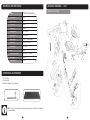
CONTENTS & ACCESSORIES
1. Cut Off Stop.
2. Coolant Tray.
3. Instruction Manual (not pictured).
1 2
27
EXPLODED DRAWING….cont
RIGHT SIDE OF THE BOW

26
EXPLODED DRAWING
LEFT SIDE OF THE BOW
11
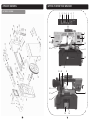
GETTING TO KNOW YOUR BANDSAW
12
11
7
9
10
19 20
25
24
23
21
15 14
13
22
1 2 3 4 5 6
17
18
16
8

12
GETTING TO KNOW YOUR BANDSAW….cont
Ref. No. Description Ref. No Description
1. Coolant Pump Switch 14. Coolant Pump
2. Emergency Stop Button 15. Coolant Tank
3. Start Button 16. End Cut Microswitch
4. Stop Button 17. Pivot Arm
5. Power Light 18. Gearbox
6. Hydraulic Cylinder Feed Rate Adjuster 19. Motor
7. Bow Feed Lock 20. Hydraulic Cylinder
8. Belt Guard 21. Coolant Nozzle
9. Right Wheel Cover 22. Movable Vice Jaw
10. Fixed Vice Jaw 23. Coolant Tap
11. Cut Off Stop 24. Blade Tensioning Knob
12. Electrical Box 25. Right Wheel Cover
13. Vice Handwheel
CONTROL PANEL
1. Coolant pump switch Turns the coolant pump on / off
2. Emergency stop button
Interrupts power to the system and stops the motor, twist
the button until it pops out to bring power back to the
machine, can also be used as a stop button.
3. Start button Turns the machine on.
4. Stop button Stops the machine.
5. Power light When lit the machine is ready for operation.
6. Hydraulic cylinder feed rate adjuster Fine tunes the feed rate on the hydraulic cylinder, 9 is
the fastest and 1 is the slowest rate of decent.
7. Bow feed lock
Turning the knob anti-clockwise lowers the saw bow at
the rate you have set on the hydraulic cylinder, turning
the knob clockwise will locks the bow into position.
1 2 3 4 5 6 7
25
Symptom Possible cause Solution
Unusual wear on side or back
of blade.
1. Blade guides are worn.
2. Blade guides not properly adjusted.
3. Blade guide brackets are loose.
1. Replace blade guides.
2. Adjust as described in manual (pg15).
3. Tighten blade guide brackets.
Excessive blade breakage
and teeth ripping from the
blade.
1. Material is loose in the vice.
2. Incorrect speed or feed.
3. Blade is too coarse.
4. Workpiece material is too coarse.
5. Incorrect blade tension.
6. Blade is in contact with material before
bandsaw is started.
7. Blade is rubbing on the wheel flange.
8. Blade guides are misaligned.
9. Blade is too thick.
10.Bad weld on blade.
1. Clamp the material securely.
2. Adjust speed or feed.
3. Use correct blade for material.
4. Use the saw at slower speed and use a
smaller tpi blade.
5. Adjust blade tension (pg16-17) so that it
does not slip on the wheel.
6. Place the blade in contact with the mate-
rial only after the saw has started.
7. Adjust the blade tracking (pg18).
8. Adjust blade guide alignment.
9. Use correct thickness blade.
10.Re-weld or replace blade.
Motor overheating.
1. Blade tension too high.
2. Drive belt tension too high.
3. Blade too coarse or too fine.
4. Gears need lubrication.
5. Blade is binding in the cut.
1. Reduce blade tension.
2. Reduce belt tension.
3. Use a blade designed for the material.
4. Lubricate the gears.
5. Decrease feed and speed.
Blade is twisting.
1. Blade tension is too high.
2. Blade is binding in the cut.
1. Decrease blade tension.
2. Decrease feed pressure.
Bad, rough or crooked cuts.
1. Blade is too coarse.
2. Blade guide assembly is loose.
3. Blade guides are spaced out too far.
4. Incorrect speed.
5. Blade is blunt.
6. Inadequate blade tension.
7. Blade guide bearings not properly adjust-
ed.
8. Feed pressure too much.
1. Use a finer blade.
2. Tighten the guide assembly.
3. Move guides closer to the material.
4. Adjust speed.
5. Replace the blade.
6. Increase blade tension a little at a time.
7. Adjust blade guide bearings.
8. Reduce feed pressure by increasing the
spring tension on the arm.
Premature blade dulling.
1. Blade tpi is too high.
2. Incorrect speed - too fast.
3. Inadequate feed pressure.
4. Hard spots or scale on the material.
5. Blade installed backwards.
6. Insufficient blade tension.
7. Work hardened material especially stain-
less.
1. Replace with a smaller tpi blade.
2. Reduce speed.
3. Increase feed pressure by unscrewing
tension bar. This will decrease the spring
tension on the arm.
4. Reduce speed, increase feed pressure.
5. Remove blade, twist inside out and rein-
stall.
6. Increase blade tension.
7. Increase feed pressure by reducing spring
pressure.
TROUBLESHOOTING

24
MAINTENANCE INSTRUCTIONS….cont
GEARBOX OIL CHANGE
Note: The gearbox oil should be replaced after the first 50 hours of running and
then every 5 months after that, failing to do this will reduce the life of the gear-
box, and void your warranty.
Note: Contact your local authority on how / where to dispose of the waste
oil, we recommend refilling with EP90 gear oil.
GENERAL MAINTENANCE
Do not used compressed air to clean the bandsaw, this can cause metal fillings
to go into the guide bearings and other parts of the bandsaw.
Always remove the metal fillings from the blade guides after use.
Wipe the bandsaw down with a dry cloth.
Check the guide bearings regularly making sure they are clean and properly
adjusted.
Always check to make sure the wire brush properly adjusted and clean.
Always disconnect from the mains supply before carrying out any maintenance.
Disconnect from the mains supply.
Lower the saw bow to its lowest horizontal
position.
Remove the oil plug (Fig.15, A) and syphon
the used oil out.
Fill the gearbox with EP90 gear oil until its
around the red dot on the oil sight glass.
Refit the oil plug.
A
B
Fig. 15
13
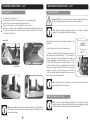
ASSEMBLY INSTRUCTIONS
Slide the cut off stop (B) through the cut off stop bracket (11) on the front of the
bandsaw, secure using the bolt on the side of the retaining bracket.
The cut off stop is ready to be used.
FITTING THE CUT OFF STOP
Before using the bandsaw it is best to clean the rust protected surfaces using kero-
sene, diesel oil or mild solvent. Never use cellulose based solvents such as paint thin-
ner or lacquer thinner as these will damage the painted surfaces.
CLEANING THE SURFACES PRIOR TO OPERATION
Danger / Caution: At least 2 persons are required to remove this bandsaw from it`s
packaging it is extremely heavy! Failing to follow this can have serious conse-
quences and could lead to personal injury and/or the possibility of damage.
Use proper lifting equipment to move the bandsaw from the wooden base and in
to your desired location.
Whist still on the wooden base, move the bandsaw to where it is too be located.
Unbolt the bandsaw from the wooden base.
Remove the bandsaw from the packaging, check the bandsaw for any signs of
damage or missing items prior to assembly.
Note: If any items are missing or damaged, DO NOT use the machine;
contact your distributor immediately.
UNPACKING
Before the bandsaw can be used the transit bolt
and bracket must be removed; this is situated at
the end of the saw bow and bed (see right pic-
ture). Keep the bolt and bracket as you may
need these if the bandsaw needs to be moved in
transit to a different location (Fig. 1).
REMOVING THE TRANSIT BOLT
Remove
Left Wheel Cover
Fig. 1

14
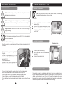
OPERATING INSTRUCTIONS
Prior to changing the blade speed make sure the mains is disconnected, Loosen and
remove the belt guard bolt and lift up the cover, this will allow access to the belt so it
can be adjusted.
Loosen the motor bracket bolt (Fig.2, A), this will allow you to move the motor more
freely.
SETTING THE BLADE SPEED
A
Fig. 2
Move the belt to the desired speed (Fig.3).
Once the belt has the desired speed adjustment, re-tension the motor and secure
in place by tightening the bolt (Fig.2).
Close the belt guard and refit and re-tighten the screw.
On page 15 is a table which will give you some idea of what speed materials should
be cut at.
95
Motor
Blade Speed mtr/min Fig. 3
73
50
29
23
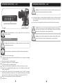
FILLING THE HYDRAULIC CYLINDER WITH OIL
The hydraulic system on this bandsaw consists of a hydraulic cylinder which is operat-
ed by a needle valve, the saw bow is raised by hand, and as this is done oil passes to
the underside of the piston. The restricted flow is controlled by the feed rate control
knob and governs the speed of which the saw bow lowers. If it becomes necessary to
fill the hydraulic cylinder with oil then follow the steps below.
Disconnect from the mains supply.
Lower the saw bow into its lowest position.
Remove the screw on top of the hydraulic cyl-
inder (Fig.14, A) and fit a 1/8” bsp tail pipe fit-
ting into its place.
Place a hose over the tail pipe fitting and put
the other end of the hose into a bottle of hy-
draulic oil.
Raise and lower the saw bow a few times until
the oil starts to seep out from the hydraulic
cylinder.
Once topped up take off the hose and tail
pipe.
Refit the screw.
MAINTENANCE INSTRUCTIONS….cont
Now adjust the left hand guide arm in the following
way.
Ensure both cap head bolts (Fig.13, D) are tight
before any adjustment is made.
Loosen the nuts on screws (Fig.13, B, C & F) but do
not remove.
Repeat step 5 for adjusting screws (B & C) for the
angle of the blade.
If the blade is not level to the right hand side of the
blade, then adjust cap head bolt (E) to move the
guide block inwards, or screws (F) to move it to-
wards you.
Once all the adjustments have been made, then
tighten cap head bolt (A) back up and tighten all
four nuts back up on screws (B, C & F). D
D
B
C
A
E
F
F
Fig. 13
A
Fig. 14

22
MAINTENANCE INSTRUCTIONS….cont
Note: The outer bearing shaft is eccentric and is the one to adjust, the
inner bearing shaft is fixed and can not be adjusted.
Remove the carbide guide by taking out the
cap head bolt (Fig. 11 ,A).
Undo the hex screw slightly (Fig. 11, B).
With a spanner turn the eccentric shaft (Fig. 11,
C) until there is a gap of about 0.001”, you
should just be able to slide a piece of paper
between the gap.
Once the eccentric shaft has be adjusted, re-
tighten the hex screw (B) and refit the carbide
guide.
Repeat steps 2-5 for the opposite eccentric
shaft. A
B
C
Fig. 11
BLADE GUIDE ALIGNMENT
Start with right fixed arm to begin with, place a set
square on the bed and against the blade to see
what adjustment is needed (Fig. 12).
Make sure both cap head bolts (D) are tight be-
fore any adjustment is made.
Slightly slacken off the cap head bolt (A) but do
not remove.
Slacken the nuts on screw (B & C), but do not re-
move them.
Adjusting screw (B) will move the top part of the
blade, or adjusting screw (C) will move the bottom
part of the blade, screwing inwards will bend the
blade towards you, screwing outwards will bend it
away from you.
Once the right side of the blade is adjusted cor-
rectly, then tighten both nuts up and re-tighten
cap head bolt (A).
C
A B
D
Fig. 12
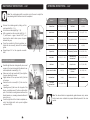
15
OPERATING INSTRUCTIONS….cont
Note: The above table is an approximate guide reference only, various
factors mean some materials may require different speeds to the ones
quoted.
Material Speed
M/Min (FPM) Material Speed
M/Min (FPM)
Carbon Steel 60 - 108 (196 - 354) Tool Steel 62 (203)
Steel Section 54 - 67 (180 - 220) High Speed Tool Steel 23 - 36 (75 - 118)
Thin Tube 54 - 67 (180 - 220) Cold Work Tool Steel 95 - 213 (29 - 65)
Aluminium Alloy 67 - 163 (220 - 534) Hot Work Tool Steel 62 (203)
Copper Alloy 70 - 147 (229 - 482) Oil Hardening Tool steel 62 - 65 (203 - 213)
Alloy Steel 34 - 98 (111 - 321) Free Machining
Stainless Steel 46 - 62 (150 - 203)
Mild Steel 75 (246) Gray Cast Iron 33 - 75 (108 - 255)
Water Hard Tool Steel 242 (74) Ductile Austenitic
Cast Iron 65 - 85 (20 - 26)
Stainless Steel 26 (85) Malleable Cast Iron 98 (321)
Cold Rolled
Stainless Steel 26 - 62 (85 - 203)

16
OPERATING INSTRUCTIONS….cont
ADJUSTING THE VICE
Loosen both lever locks (Fig. 4).
Slide the fixed vice jaw to the left and move it to your desired angle.
Once set at your desired angle re-tighten the lever lock.
Place the material to be cut flush against the fixed vice jaw.
Slide the movable vice jaw up tight against the material and tighten the lever lock.
For maximum cutting at 90˚ remove the fixed vice jaw and bolt it down on the left
hand side hole (Fig. 5, B).
Adjusted to 90˚
Adjusted to 45˚
Note: Always tighten both lever locks prior to making a cut, leaving them
loose will allow the jaws to slip and could damage the material or even
cause personal injury.
B
Fig. 5
Lever Lock
Fig. 4
Lever Lock
21
MAINTENANCE INSTRUCTIONS….cont
Note: The correct guide bearing adjustment is very important, this will
make the blade run smoother and evenly without any snagging or twisting
whilst the blade is running. It will also prolong the blade life.
BLADE GUIDE BEARING ADJUSTMENT
Blade tension is important for the proper operation of the
bandsaw.
To set the blade correctly use the following steps.
To tension the blade, lift up the left wheel cover and turn
the blade tension hand-wheel (Fig. 10, A) clockwise, a
tension scale (B) is located underneath the wheel. The
scale is graduated to indicate blade tension of 20,000,
25,000 and 35,000 pounds per square inch (psi). For car-
bon blades (similar to the one supplied with the machine)
the blade should be tensioned at 20,000 psi. For bi-metal
blades, the blade should be tensioned at 25,000 or
35,000 psi. Always release the blade tension at the end of
each work day to prolong blade life.
Note: Before tensioning the blade make sure the blade is properly
aligned, If not, align before attempting to tension.
Caution: DO NOT over tension the blade as this will warp and stretch the
blade, if the blade warps or stretches then it must be replaced.
TENSIONING THE BLADE
A
B
Note: The tension scale is a guide only; there are many factors that can
alter the ideal tension of the blade.
Fig. 10

20
MAINTENANCE INSTRUCTIONS
Caution: Before carrying out any maintenance always disconnect the
bandsaw from the mains supply.
Note: The bandsaw was designed to use a 3280 x 0.9 mm size blade, al-
ways use this size blade.
Caution: We strongly advise wearing gloves for protection when changing
blades, blades are sharp and dangerous and can cause personal injury.
CHANGING THE BLADE
Danger / Caution: Blades are sharp use extra care when removing, in-
stalling or handling.
Disconnect from the mains supply.
Raise the saw bow to around 6” and turn the feed control knob clockwise to lock it
in position.
Remove the blade from both wheels and slide it out of both blade guides.
Before fitting the new blade its best to clean the wheels of any swarf.
Place the new blade onto the wheels and between the blade guides.
Tension the blade, re-adjust the blade guides and track the blade.
Once adjustments have been made close both wheels covers and lower the saw
bow.
Slide the left blade guard arm (Fig. 9, A) to
the right.
Take the two cap head bolts (Fig. 9, B) out
and remove the adjustable blade guard
bracket (Fig. 9, C).
Open both wheel covers.
Release the blade tension by turning the
blade tension handwheel anti-clockwise.
B
C
A
Fig. 9
17
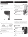
OPERATING INSTRUCTIONS….cont
Slide the coolant tank out from the rear of the
bandsaw (Fig. 6).
Ensure the filter is fitted and fill with fresh coolant.
Slide the coolant tank back onto the bandsaw
panel, ensuring that the coolant hose is situated
over the filter.
Note: We recommend the use of water soluble coolant, this will prolong
the blade life and make the cut more efficient.
FILLING THE COOLANT TANK
The hydraulic cylinder has an adjustable rate of decent, this can be adjusted by turn-
ing the hydraulic cylinder feed rate adjuster (Fig. 8) clockwise to slow down the rate of
decent, or anti-clockwise to speed up the rate of decent. The hydraulic cylinder can
be stopped in any position by turning the hydraulic cylinder feed rate adjuster , when
the knob is fully turned clockwise the cylinder will stop descending.
HYDRAULIC CYLINDER ADJUSTMENT
Fig. 6
ADJUSTING THE GUIDE ARM
Loosen the guide arm knob (Fig. 7).
Slide the guide arm close to the material that
is to be cut.
Re-tighten the guide arm knob.
Fig. 7
Guide Arm Knob

18
OPERATING INSTRUCTIONS….cont
Disconnect from the mains supply.
Change the blade speed to suit the material that is to be cut (see pg14 changing
the blade speed).
Raise the saw bow to a vertical position.
Adjust the cut length stop to your desired position.
Set the vice angle to your desired position.
Open the vice and insert the material to be cut then close the vice to secure.
Move the two adjustable blade guides closer to the material, but make sure it
doesn't foul against it.
Adjust the rate of descent of the arm as described on pg17 so that it is creeping
slowly down towards the material, shut off the hydraulic cylinder when the blade
gets close to the material, do not start cutting on a sharp edge, file it off first.
Plug in to the mains supply and turn the coolant pump on.
Start the saw.
Danger: Before attempting to cut always ensure all covers are in place,
undamaged and secure.
Note: The harder the material to be cut the slower the speed should be.
CUTTING WITH THE BANDSAW
Note: Check maintenance on how to replace the oil or top up the hy-
draulic cylinder.
Hydraulic Cylinder
Fig. 8
Hydraulic Cylinder Feed Rate Adjuster
19
OPERATING INSTRUCTIONS….cont
To bring the blade in to contact with the material to be cut, turn the feed control
knob, if the blade jams immediately turn the bandsaw off and refer to the trouble-
shooting guide.
Once the cut is complete then turn the machine off and remove the material.
Caution: Do not turn the machine on until the material is secured and the
blade has been lowered just above the material.
Caution: Never remove the material when the bandsaw is still running, al-
ways switch the machine off before attempting to remove the material,
failure to do this could lead to serious personal injury.
Caution: Never start the bandsaw with the blade in contact with the work-
piece. Allow the saw to reach full speed before commencing cut.
-
 1
1
-
 2
2
-
 3
3
-
 4
4
-
 5
5
-
 6
6
-
 7
7
-
 8
8
-
 9
9
-
 10
10
-
 11
11
-
 12
12
-
 13
13
-
 14
14
-
 15
15
-
 16
16
-
 17
17
-
 18
18


Ask a question and I''ll find the answer in the document
Finding information in a document is now easier with AI
Related papers
Other documents
-
SIP INDUSTRIAL 01599 User manual
-
Femi FEMSN105XL User manual
-
Jet Tools HBS-1321W WMH User manual
-
JET MBS-1014W-1 Owner's manual
-
Harbor Freight Tools 93762 User manual
-
Central Machinery 93762 Set Up And Operating Instructions Manual
-
-
General International 90-320 M1 User guide
-
-