Page is loading ...

Reflex MBM II Membranbruchmelder
reflex MBM II Diaphragm rupture detector
Montage-, Betriebs- und Wartungsanleitung
Installation, operating and maintenance instructions
Allgemeine Sicherheitshinweise
Der MBM II Membranbruchmelder ist eine elektrische Schalteinrich-
tung, die nur entsprechend den Hinweisen in dieser Anleitung einge-
setzt werden darf. Die elektrische Verkabelung und der Anschluss sind
von einem Fachmann nach dem gültigen EVU und VDE Vorschriften
auszuführen. Vor den Arbeiten an elektrischen Bauteilen ist die Anlage
spannungsfrei zu schalten.
Das Missachten dieser Anleitung, insbesondere der Sicherheitshinwei-
se, kann zur Zerstörung und Defekten am MBM II Membranbruchmel-
der führen, Personen gefährden sowie die Funktion beeinträchtigen.
Bei Zuwiderhandlung sind jegliche Ansprüche auf Gewährleistung und
Haftung ausgeschlossen.
Montage, Inbetriebnahme
→ auch Seite 2
– Die Anschlüsse A1 und A2 sind spannungsfrei geschaltet.
– Elektrodenrelais (3) an Wand o. ä. in unmittelbarer Nähe des
Gefäßes befestigen. Vorher ist das Gehäuse abzuschrauben.
– Kabelverbindungen herstellen, es stehen 4 Kabeleingänge zur
Verfügung (Kabel bauseits).
Liefergrenze Reflex = Klemmleiste Elektrodenrelais (3)
- Klemme Min. mit Stecker 2.2 der Eletrode (2) verbinden. Dazu
Stecker 2.2 abziehen, Kabel einstecken und vorher gelöste
Schraube im Stecker 2.2 festziehen.
- Klemme Max. (Masse) mit Erdungsblech (2.1) verbinden, vorher
Kabel abisolieren.
- Falls gewünscht, an die Klemmen 11, 12, 14 potenzialfreien
Ausgang anschließen.
- Klemmen A1 und A2 für Eingangsspannung anschließen.
– Empfindlichkeit am Potenziometer (3.3) auf 20 kΩ einstellen
(= Werkseinstellung).
– Gehäuse anschrauben.
– Zuleitungen A1 und A2 mit Spannung versorgen.
Der MBM II ist jetzt in Betrieb.
Betrieb → auch Seite 2
Der Betrieb ist nur mit angeschraubtem Gehäuse statthaft.
– Normalbetrieb : grüne LED leuchtet
– Membranbruch : gelbe LED leuchtet
Membranbruch kann zu vollständigem Funktionsausfall des Membran-
Druckausdehnungsgefäßes führen. Bitte verständigen Sie umgehend
Ihren Reflex-Servicedienst.
Funktion, Voraussetzungen für die Montage
→ auch Seite 2
– Das Membran-Druckausdehnungsgefäß muss werksseitig für die
Montage des MBM II vorbereitet sein und im unteren Drittel eine
Muffe Rp 1/2 (1) besitzen. Ein nachträgliches Einschweißen der Muffe
ist unzulässig.
– Funktion:
Im Falle von Membranbruch wird durch eindringendes Wasser in den
Gasraum der elektrische Kontakt zwischen Masse (Erdungsblech
2.1) und Stecker (2.2) hergestellt und ein Signal ausgelöst.
Einsatzbereiche, Betriebsparameter
Der MBM II wird zur Signalisierung von Membranbruch bei Membran-
Druckausdehungsgefäßen in Heizungs-, Kühl- und Trinkwassersyste-
men eingesetzt. Er besteht im wesentlichen aus der Elektrode und dem
Elektrodenrelais.
Elektrode (2)
zul. Betriebstemperatur : tmax ≤ 70°C
zul. Betriebsüberdruck : pmax ≤ 25 bar
Elektrodenrelais (3)
Spannungsversorgung : 230 V, 50 Hz
potenzialfreier Ausgang (Wechsler) : ≤ 250 V
Ansprechempfindlichkeit : 5 - 100 kΩ (am Poti einstellbar)
Schutzgrad im Gehäuse : IP 66
General Safety Instructions
The MBM II diaphragm rupture detector is an electrical switchgear that
may be exclusively used in accordance with the notes contained her-
ein. The electrical cabling and the connection must be performed by a
specialist according to the applicable EVU and VDE provisions. Prior to
performing any work on electrical components, it must be ensured that
the system is not alive.
The non-compliance with the present instruction, in particular the no-
tes on safety, may lead to the destruction and faults of the MBM II
diaphragm rupture detector, to personal injuries and may affect the
function. In case of the violation of such instruction, any and all claims
for warranty and liability are excluded.
Assembly, Commissioning
→ also page 2
– The connections A1 and A2 are connected off-circuit.
– Mount the electrode relay (3) on a wall or similar in the immediate
vicinity of the vessel. Unscrew the housing in advance.
– Establish the cable connections. Four cable inputs are
available (cables to be provided on site).
Reflex delivery limit = terminal block electrode relay (3)
- Connect the min. terminal with plug 2.2 of the electrode (2). To do
so, disconnect plug 2.2, insert the cable, and fasten the previously
released screw in the plug 2.2.
- Connect the max. terminal (mass) with the earthing plate (2.1),
strip the cable insulation in advance.
- If desired, connect a floating output to the terminals 11, 12, 14.
- Connect the terminals A1 and A2 for the input voltage.
– Set the sensitivity on the potentiometer (3.3) to 20 kΩ
(= factory setting).
– Fasten the housing with screws.
– Supply the feed lines A1 and A2 with power.
Now, the MBM II is operational.
Operation → also page 2
The operation is only admissible if the housing is fastened with screws.
– Regular operation : green LED is on
– Diaphragm rupture : yellow LED is on
A diaphragm rupture can result in the complete functional failure of
the diaphragm expansion vessel. Please contact your Reflex service
immediately.
Function, Installation Requirements
→ also page 2
– The diaphragm expansion vessel must be prepared on site for the
installation of the MBM II and must provide of a Rp 1/2 (1) sleeve in
the lower third. A subsequent welding of the sleeve is not admissible.
– Function:
In the event of a diaphragm rupture, the electrical contact between
the mass (earthing plate 2.1) and the plug (2.2) is established by
water penetrating into the gas space, and a signal is triggered.
Application, Operating Parameters
The MBM II is used for the signalling of a diaphragm rupture of
diaphragm expansion vessels in heating, cooling, and drinking water
systems. It mainly consists of the electrode and the electrode relay.
Electrode (2)
permiss. operating temperature : tmax ≤ 70°C
permiss. operating excess pres. : pmax ≤ 25 bar
Electrode relay (3)
Power supply : 230 V, 50 Hz
floating output (change-over cont.) : ≤ 250 V
response sensitivity : 5 - 100 kΩ (adjustable on potentiometer)
degree of protection in the housing : IP 66

Reflex MBM II Membranbruchmelder
Reflex MBM II Diaphragm rupture detector
SI0216de-enC / 08 - 14
Sachnummer: 9119394
Technische Änderungen vorbehalten
Technical details subject to modification
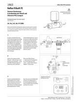
Montage- und Lieferübersicht Overview of the Installation and Delivery
1 Rp½ sleeve on the vessel
2 Electrode, with vessels which have a constant
pre-set pressure sealed into the vessel sleeve
(1) in the factory, otherwise enclosed for
on-site installation.
2.1 Earthing plate
2.2 detachable plug
2.3 Angle
3 Electrode relay in the housing
3.1 green LED, is on during the regular operation
3.2 yellow LED, is on during in case of a
diaphragm rupture
3.3 Potentiometer to adjust the response sensitivity
4 Transport protection for the electrode (2),
channel section made of foamed material,
remove prior to the installation
Konformitätserklärung
Das Elektrodenrelais ist für den Einsatz im MBM II geeignet
und wird folgenden Normen gerecht:
VDE 0435, VDE 0609, VDE 0110, VBG 4, IEC 158-1,
IEC 255-0-20, IEC 255-3 & 6, IEC 255-8 & 17, IEC 255-22-1,
IEC 255-22-2, IEC 255-5, IEC 801-4, IEC 67.1.5 1 & 18,
DIN 46277, IEC 529, DIN 40050, NFC 20010
Zulassungen:
UL, CSA
Declaration of Conformity
The electrode relay is suited for the deployment in the
MBM II and complies with the following standards:
VDE 0435, VDE 0609, VDE 0110, VBG 4, IEC 158-1,
IEC 255-0-20, IEC 255-3 & 6, IEC 255-8 & 17, IEC 255-22-1,
IEC 255-22-2, IEC 255-5, IEC 801-4, IEC 67.1.5 1 & 18,
DIN 46277, IEC 529, DIN 40050, NFC 20010
Approvals:
UL, CSA
Netz 230 V, 50 Hz
Network 230 V, 50 Hz
A1
2
A2
Max. Min.
11/12/14
2 x einadriges Kabel mit Gummimantel
∅ 6,4 mm x 2,5 mm, NSGAFÖU (bauseits)
2 x single-wire cable with rubber sheath
∅ 6.4 mm x 2.5 mm, NSGAFÖU (on site)
1
2.2
2.3
2.1
4
1 Muffe Rp½ am Gefäß
2 Elektrode, bei Gefäßen mit konstantem
Vordruck werksseitig in Behältermuffe
(1) eingedichtet, ansonsten beigelegt
zur bauseitigen Montage.
2.1 Erdungsblech
2.2 abziehbarer Stecker
2.3 Winkel
3 Elektrodenrelais im Gehäuse
3.1 grüne LED, leuchtet bei Normalbetrieb
3.2 gelbe LED, leuchtet bei Membranbruch
3.3 Potenziometer zur Einstellung der
Ansprechempfindlichkeit
4 Transportschutz für Elektrode (2),
U-Profil aus Schaumstoff, vor der
Montage abnehmen
3
3.3
3.2
3.1
Reflex Winkelmann GmbH
Gersteinstraße 19
59227 Ahlen - Germany
Telefon: +49 2382 7069-0
Telefax: +49 2382 7069-588
www.reflex.de
/