Page is loading ...

P/NO : 3828A10001U
www.lg.com
INSTALLATION MANUAL
AIR CONDITIONER
• Please read this installation manual completely before installing the product.
• Installation work must be performed in accordance with the national wiring
standards by authorized personnel only.
• Please retain this installation manual for future reference after reading it
thoroughly.
TYPE : CEILING CASSETTE
“The equipment complies with requirements of the Technical Regulation, in
terms of restrictions for the use of certain dangerous substances in electrical
and electronic equipment.”
ENGLISH
РУССЛИЙ ЯЗЫК

2 Ceiling Cassette Air Conditioner
Ceiling Cassette Air Conditioner Installation Manual
TABLE OF CONTENTS
Safety Precautions............................3
Introduction........................................6
Symbols used in this Manual..........6
Features ...........................................6
Installation ..........................................7
Installation Tools ..............................7
Installation of Indoor, Outdoor
Unit
..................................................8
Air purging......................................20
Test running
.................................22
Optional operation
.....................24
Installation guide at the seaside...27
o
Connecting cable
o
Pipes: Gas side
Liquid side
o
Hanging Bolt
(W 3/8 or M10 length 650mm)
o
Insulated drain hose
o
Additional Drain hose
(Inner Dia.............32mm)
o
Horizontal meter
o
Screw driver
o
Electric drill
o
Hole core drill (ø70mm)
o
Flaring Tools set
o
Torque Wrenches
o
Hexagonal Wrench (4mm, 5mm)
o
Gas-leak detector
o
Ownerʼs Manual
o
Installation Manual
o
Thermometer
Installation
Requirements
Required Parts Required Tools

Installation Manual 3
Safety Precautions
ENGLISH
To prevent injury to the user or other people and property damage, the following instructions
must be followed.
n
Incorrect operation due to ignoring instruction will cause harm or damage. The seriousness
is classified by the following indications.
n Meanings of symbols used in this manual are as shown below.
This symbol indicates the possibility of death or serious injury.
This symbol indicates the possibility of injury or damage.
Be sure not to do.
Be sure to follow the instruction.
Safety Precautions
n Installation
Do not use a defective or
underrated circuit breaker.
Use this appliance on a
dedicated circuit.
• There is risk of fire or electric
shock.
For electrical work, contact
the dealer, seller, a qualified
electrician, or an Authorized
Service Center.
• Do not disassemble or repair
the product. There is risk of fire
or electric shock.
Always ground the product.
• There is risk of fire or electric
shock.
Install the panel and the cover
of control box securely.
• There is risk of fire or electric
shock.
Always install a dedicated
circuit and breaker.
• Improper wiring or installation
may cause fire or electric shock
Use the correctly rated breaker
or fuse.
• There is risk of fire or electric
shock.
Do not modify or extend the
power cable.
• There is risk of fire or electric
shock.
Do not install, remove, or re-
install the unit by yourself
(customer).
• There is risk of fire, electric
shock, explosion, or injury.
Be cautious when unpacking
and installing the product.
•
Sharp edges could cause injury. Be
especially careful of the case edges
and the fins on the condenser and
evaporator.
For installation, always contact the dealer or
an Authorized Service Center.
• There is risk of fire, electric
shock, explosion, or injury.
Do not install the product on a
defective installation stand.
• It may cause injury, accident, or
damage to the product.
Be sure the installation area
does not deteriorate with age.
•
If the base collapses, the air
conditioner could fall with it,
causing property damage, product
failure, and personal injury.

4 Ceiling Cassette Air Conditioner
Safety Precautions
n Operation
Do not plug or unplug the
power supply plug during
operation.
• There is risk of fire or electric
shock.
Do not touch(operate) the
product with wet hands.
• There is risk of fire or electrical
shock.
Do not place a heater or other
appliances near the power
cable.
• There is risk of fire and electric
shock.
Do not let the air conditioner run for a long
time when the humidity is very high and a
door or a window is left open
.
• Moisture may condense and wet
or damage furniture.
Take care to ensure that power
cable could not be pulled out or
damaged during operation.
• There is risk of fire or electric
shock.
Do not place anything on the
power cable.
• There is risk of fire or electric
shock.
Do not allow water to run into
electric parts.
• It may cause There is risk of fire,
failure of the product, or electric
shock.
Do not store or use flammable
gas or combustibles near the
product.
• There is risk of fire or failure of
product.
Do not use the product in a
tightly closed space for a long
time.
• Oxygen deficiency could occur.
When flammable gas leaks,
turn off the gas and open a
window for ventilation before
turn the product on.
• Do not use the telephone or turn
switches on or off.
There is risk of explosion or fire
If strange sounds, or small or
smoke comes from product. Turn
the breaker off or disconnect the
power supply cable.
• There is risk of electric shock or
fire.
Stop operation and close the window in
storm or hurricane. If possible, remove
the product from the window before the
hurricane arrives.
• There is risk of property damage,
failure of product, or electric
shock.
Do not open the inlet grill of the
product during operation.
(Do not touch the electrostatic
filter, if the unit is so equipped.)
• There is risk of physical injury,
electric shock, or product failure.
When the product is soaked
(flooded or submerged),
contact an Authorized Service
Center.
• There is risk of fire or electric
shock.
Be cautious that water could
not enter the product.
• There is risk of fire, electric shock,
or product damage.
Ventilate the product from time to time when
operating it together with a stove, etc.
• There is risk of fire or electric shock.
Turn the main power off when cleaning or
maintaining the product.
• There is risk of electric shock.
When the product is not be used for a long
time, disconnect the power supply plug or turn
off the breaker.
• There is risk of product damage or failure, or
unintended operation.
Take care to ensure that nobody could step on
or fall onto the outdoor unit.
• This could result in personal injury and product
damage.

Installation Manual 5
ENGLISH
Safety Precautions
n Installation
n Operation
Always check for gas (refrigerant)
leakage after installation or repair
of product.
• Low refrigerant levels may cause
failure of product.
Install the drain hose to
ensure that water is drained
away properly.
• A bad connection may cause
water leakage.
Keep level even when
installing the product.
• To avoid vibration or water
leakage.
Do not install the product where the
noise or hot air from the outdoor unit
could damage the neighborhoods.
• It may cause a problem for your
neighbors.
Use two or more people to lift
and transport the product.
• Avoid personal injury.
Do not install the product where
it will be exposed to sea wind
(salt spray) directly.
•
It may cause corrosion on the product.
Corrosion, particularly on the condenser
and evaporator fins, could cause product
malfunction or inefficient operation.
Do not expose the skin directly to cool air for
long periods of time.
(Don't sit in the draft.)
• This could harm to your health.
Do not use the product for special purposes, such as
preserving foods, works of art, etc. It is a consumer air
conditioner, not a precision refrigeration system.
• There is risk of damage or loss of property.
Do not block the inlet or
outlet of air flow.
• It may cause product failure.
Use a soft cloth to clean. Do
not use harsh detergents,
solvents, etc.
• There is risk of fire, electric
shock, or damage to the plastic
parts of the product.
Do not touch the metal parts of
the product when removing the
air filter. They are very sharp!
• There is risk of personal injury.
Do not step on or put anyting
on the product. (outdoor
units)
• There is risk of personal injury
and failure of product.
Always insert the filter securely.
Clean the filter every two weeks or
more often if necessary.
• A dirty filter reduces the efficiency
of the air conditioner and could
cause product malfunction or
damage.
Do not insert hands or other objects
through the air inlet or outlet while the
product is operated.
• There are sharp and moving
parts that could cause personal
injury.
Do not drink the water
drained from the product.
• It is not sanitary and could cause
serious health issues.
Use a firm stool or ladder
when cleaning or maintaining
the product.
• Be careful and avoid personal
injury.
Replace the all batteries in the
remote control with new ones of
the same type. Do not mix old
and new batteries or different
types of batteries.
• There is risk of fire or explosion
Do not recharge or disassemble the batteries.
Do not dispose of batteries in a fire.
• They may burn or explode.
If the liquid from the batteries gets onto your skin
or clothes, wash it well with clean water. Do not
use the remote if the batteries have leaked.
• The chemicals in batteries could cause burns or
other health hazards.

6 Ceiling Cassette Air Conditioner
Introduction
This symbol alerts you to the risk of electric shock.
This symbol alerts you to hazards that may cause harm to the
air conditioner.
This symbol indicates special notes.
NOTICE
Introduction
Symbols used in this Manual
Features
Anti-bacteriaAnti-bacteriaAnti-bacteria
Heat Pump Model
Cooling Model
Remote
Controller
Air Outlet
Air
Intake
Signal Receptor
Signal Receptor

Installation
Installation Manual 7
ENGLISH
Installation
Installation Tools
Figure FigureName
Screw driver
Electric drill
Measuring tape, Knife
Hole core drill
Spanner
Torque wrench
Ohmmeter
Hexagonal wrench
Ammeter
Gas-leak detector
Thermometer,
Horizontal meter
Flaring tool set
Name

8 Ceiling Cassette Air Conditioner
Installation
Installation of Indoor, Outdoor Unit
Selection of the best location
1) Indoor unit
• There should not be any heat source or steam
near the unit.
• There should not be any obstacles to prevent
the air circulation.
• A place where air circulation in the room will
be good.
• A place where drainage can be easily
obtained.
• A place where noise prevention is taken into
consideration.
• Do not install the unit near the door way.
• Ensure the spaces indicated by arrows from
the wall, ceiling, or other obstacles.
• The indoor unit must keep the maintenance
space.
2) Outdoor unit
• If an awning is built over the unit to prevent
direct sunlight or rain exposure, be careful that
heat radiation from the condenser is not
restricted.
• There should not be any animals or plants
which could be affected by hot air discharged.
• Ensure the spaces indicated by arrows from
the wall, ceiling, fence or other obstacles.
Unit:cm
Ceiling
Ceiling Board
Ceiling Board
30 or more
Above 250
400 or less
100
or more
50 or
more
50 or
more
30 or less
Floor
More than
30cm
Fence or
obstacles
More than 70cm
More than 50cm
More than
More than
30cm
30cm
More than
30cm
Sunroof

Installation
Installation Manual 9
ENGLISH
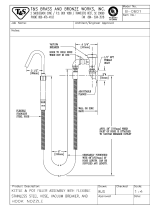
3) Piping length and the elevation
Outdoor unit
Indoor unit
A
B
Outdoor unit
Indoor unit
A
B
A
Oil trap
If piping length is more than 10m
Outdoor unit
Indoor unit
B
CAUTION:
• Rated performance for refrigerant line length of:7.5m
• Capacity is based on standard length and maximum allowance length is on the
basis of reliability.
• Improper refrigerant charge may result in abnormal cycle.
• Oil trap should be installed every 10 meters.
Model
*Additional
refrigerant
(g/m)
Pipe Size
mm(inch)
Length A(m) Elevation B(m)
Gas Liquid Standard Max. Standard Max.
18kBtu/h 12.7(1/2") 6.35(1/4") 7.5 30 5 20 20
24kBtu/h 15.88(5/8") 6.35(1/4") 7.5 50 5 30 35
28kBtu/h 15.88(5/8") 6.35(1/4") 7.5 50 5 30 35
36kBtu/h 15.88(5/8") 6.35(1/4") 7.5 50 5 30 50
48kBtu/h 19.05(3/4") 9.52(3/8") 7.5 50 5 30 45
54kBtu/h 19.05(3/4") 9.52(3/8") 7.5 50 5 30 60

10 Ceiling Cassette Air Conditioner
Installation
• Select and mark the position for fixing bolts and
piping hole.
• Decide the position for fixing bolts slightly tilted to
the drain direction after considering the direction of
drain hose.
• Drill the hole for anchor bolt on the ceiling.
• The hole size for four anchor bolts is
Ø 14.5mm & 40mm depth.
CAUTION:
• This air-conditioner uses a drain pump.
• Horizontly install the unit using a level gauge.
• During the installation, care should be taken
not to damage electric wires.
• Thoroughly study the following installation locations:
1. In such places as restaurants and kitchens, considerable amount of oil steam and flour
adhere to the turbo fan, the fin of the heat exchanger and the drain pump, resulting in heat
exchange reduction, spraying, dispersing of water drops, drain pump malfunction, etc.
In these cases, take the following actions:
• Make sure that the ventilation fan for smoke-collecting hood on a cooking table has
sufficient capacity so that it draws oily steam which should not flow into the suction of the
air conditioner.
• Make enough distance from a cooking room to install the air conditioner in such a place
where it may not suck in oily steam.
2. Avoid installing air conditioner in such circumstances where cutting oil mist or iron powder is
in suspension in factories, etc.
3. Avoid places where inflammable gas is generated, flows in, is stored or vented.
4. Avoid places where sulfurous acid gas or corrosive gas is generated.
5. Avoid places near high frequency generators.
NOTICE
Ceiling opening dimensions and hanging bolt location
• The dimensions of the paper model for installing are the same as those of the ceiling opening dimensions.
Ceiling board
Level gauge
Ceiling
Use the ventilation fan
for smoke-collecting
hood with sufficient
capacity.
Cooking table
Air conditioner
Take enough
distance
Unit:mm
810
785
30
30
672
810
3030
840
Indoor
840
Unit:mm
570 Unit size
570 Unit size
450 (Hanging bolt)
7575
600 (Ceiling opening)
600 (Ceiling opening)
521(Hanging bolt)
39.5
39.5
Grade :18kBtu/h
Grade : 24k/28k/36kBtu/h
48k/54kBtu/h

Installation Manual 11
ENGLISH
Installation
The Indoor Unit Installation
• The following parts is option.
① Hanging Bolt - W 3/8 or M10
② Nut - W 3/8 or M10
③ Spring Washer - M10
④ Plate Washer - M10
• Drill the piping hole on the wall slightly tilted to the
outdoor side using a Ø 70 hole-core drill.
Wall
Indoor
Outdoor
Set screw of
paper model (4 pieces)
Paper model
for installation
Ceiling board
150mm
Ceiling board
Ceiling
Flat washer for M10
(accessory)
Keep the length of the bolt
from the bracket to 40mm
Open the ceiling board
along the outer edge of the
paper model
Flat washer for M10
(accessory)
Hanging bolt
(W3/8 or M10)
Nut
(W3/8 or M10)
Nut
(W3/8 or M10)
Spring washer
(M10)
Air Conditioner body
Keep the length of 15~18mm
between the air conditioner bottom
surface and the ceiling surface
Slope gradient for drain
Should be 1/50 ~ 1/100
CAUTION:
Tighten the nut and
bolt to prevent unit falling.
Remote Controller Installation
• Although the room temperature sensor is in the indoor unit, the remote controller should be installed in
such places away from direct sunlight and high humidity.
Installation of the remote controller
• Select places that are not splashed with water.
• Select control position after receiving customer approval.
• The room temperature sensor is built in the indoor unit.
• This remote controller equipped with liquid crystal display. If this position is higher or lower, display is difficult to
see.(The standard height is 1.2 ~ 1.5m high)
Routing of the remote controller cord
• Keep the remote controller cord away from the refrigerant piping and the drain piping.
• To protect the remote controller cord from electrical noise, place the cord at least 5cm away from other power
cables (audio equipment, television set, etc.)
• If the remote controller cord is secured to the wall, provide a trap at the top of the cord to prevent water
droplets from running.

12 Ceiling Cassette Air Conditioner
Installation
1. Remove the battery cover from the remote controller.
• Slide the cover according to the arrow direction.
2. Insert the two batteries.
• Be sure that the (+) and (-) directions are correct.
• Be sure that both batteries are new.
3. Re-attach the cover.
• Slide it back into position.
• Fix the under plate on the wall
• Separate the under plate from Remote control box.
• Fix the cord clamps on the wall by
ø 3 tapping screws (accessory).
• Fix the remote control cord.
Remote control
box body
Cord clamp
(accessory)
Lever carefully
the box open
using a screw
driver, etc.
Front case
The lower part
Face of wall
Under plate
Screw (accessory)
WIRED REMOTE CONTROL INSTALLATION
REMOTE CONTROL PREPARATION
DISASSEMBLING
ELECTRICAL WIRING
HOW TO MOUNT ONTO A WALL
HOW TO INSERT BATTERIES
Main PCB
RD YL BR
Be careful not to
exchange the color
of wires.
RD YLBR
White Connector
Green Connector
• Do not use rechargeable
batteries, such batteries differ
from standard dry cells in
shape, dimensions, and
performance.
• Romove the batteries from the
remote controller if the air
conditioner is not going to be
used for some long time.
HOW TO INSERT BATTERIES

The power cord connected to the outdoor unit
should be complied with the following specifications
(Rubber insulation, type H05RN-F approved by HAR
or SAA).
If the supply cord is damaged, it must be replaced by a special cord or assembly available from the manufacturer
or its service agent.
The connecting cable connected to the indoor and
outdoor unit should be complied with the following
specifications (Rubber insulation, type H05RN-F
approved by HAR or SAA).
CAUTION
2
0mm
GN/
YL
20mm
G
N/YL
2
0mm
GN/
YL
2
0mm
GN/
YL
NORMAL
CROSS-SECTIONAL
AREA 0.75mm
2
(18k/24k/36k)
(42k/48k/54k/60k)
Capacity 1 Phase
18k/24k/28k/30k
Btu/h
36kBtu/h
42k/48k/54k/60k
Btu/h
2.5mm
2
5.5mm
2
8.5mm
2
Cooling Only
Heat Pump
4 x 0.75
(Including Earth)
5 x 0.75
(Including Earth)
Capacity 3 Phase
36kBtu/h
42k/48k/54k/60k
Btu/h
1.25mm
2
(H07RN-F)
3.5mm
2
Installation Manual 13
ENGLISH
Installation
Wiring Connection
• Open the control box cover and connect the Remote controller cord and Indoor power wires.
Terminal Block of Outdoor Unit
1(L) 2(N) 3 4 5 1(L) 2(N) 3 4 5
Terminal Block of Indoor Unit
POWER INPUT
RS T N
POWER INPUT
RS T N
3Phase
36k/42k/48k/54k/60k
Heat Pump Model.
Terminal Block of Outdoor Unit
1(L) 2(N)1(L) 2(N) 3 4 1(L) 2(N) 3 4 5
Terminal Block of Indoor Unit
POWER INPUT
Fire Prevention Cover
Connector fitting cover
Fire Prevention cover bolt
Indoor Outdoor
Connecting wire
Remote Control Cord
Cord Clip
1Phase
18k/24k/28k
Heat Pump Model.
Terminal Block of Outdoor Unit
1(L) 2(N) 3 1(L) 2(N) 3 4 5
Terminal Block of Indoor Unit
3Phase
36k/42k/48k/54k/60k
Cooling Model.
Terminal Block of Outdoor Unit
1(L) 2(N)1(L) 2(N) 3 4 1(L) 2(N) 3 4 5
Terminal Block of Indoor Unit
POWER INPUT
1Phase
18k/24k/28k
Cooling Model.
Electricwire
Round crimp-style terminal
Attach insulation sleeve
Connect wires of the same gauge to both sides
WARNING: Make sure that the screws of the terminal are free from
looseness.

14 Ceiling Cassette Air Conditioner
Installation
1. All wiring must comply with LOCAL REGULATIONS.
2. Select a power source that is capable of supplying the current required by the air conditioner.
3. Feed the power source to the unit via a distribution switch board designed for this purpose.
4. The terminal screws inside the control box may be loose due to vibration during transport.
Check the screws for loose connection.
(Running the air conditioner with loose connection can overload and damage electrical components.)
5. Always ground the air conditioner with a grounding wire and connector to meet the LOCAL REGULATION.
Main power source
Switch box
Refrigerant pipe
Circuit Breaker
Use circuit breaker or time delay fuse.
ELECTRICAL WIRING
CONNECTING THE CABLE TO OUTDOOR UNIT
1. Remove the Cover control from the unit by loosening a screw.
Connect the wires to the terminals on the control board
individually as following.
2. Secure the cable onto the control board with the holder
(clamper).
3. Refix the cover control to the original position with the screw.
4. Use a recognized circuit breaker between the power source
and the unit.
a disconnecting device to adequately disconnect all supply
lines must be fitted.
Outdoor unit
Terminal block
Connecting
cable
Cover control
Holder for
connecting
cable
Over 5mm
Holder for
power supply
cord
Power supply
cord
Grade
18k 24k 28k 36k 48k 54k
30 30 30 30 40 40
Circuit
Bracker (A)

Installation Manual 15
ENGLISH
Installation
• Preparation of Piping
Connecting Pipes to the Indoor Unit
Main cause of gas leakage is defect in flaring
work. Carry out correct flaring work in the
following procedure.
1) Cut the pipes and the cable.
• Use the accessory piping kit or the pipes
purchased locally.
• Measure the distance between the indoor and
the outdoor unit.
• Cut the pipes a little longer than measured
distance.
• Cut the cable 1.5m longer than the pipe length.
2) Burrs removal
• Completely remove all burrs from the cut cross
section of pipe/tube.
• Put the end of the copper tube/pipe to downward
direction as you remove burrs in order to avoid
to let burrs drop in the tubing.
3) Putting nut on
• Remove flare nuts attached to indoor and
outdoor units, than put them on pipe/tube having
completed burr removal.
(Not possible to put them on after flaring work)
4) Flaring work
• Carry out flaring work using flaring tool as shown
below.
Firmly hold copper tube in a bar(or die) as
indicated dimension in the table above.
5) Check
n Compare the flared work with figure below.
n If flare is noted to be defective, cut off the flared
section and do flaring work again.
• If the piping and the drain hose are in common
direction bundle the piping and the drain hose
together by wrapping them with vinyl tape.
Copper
tube
90°
Slanted Uneven Rough
Pipe
Reamer
Point down
Flare nut
Copper tube
Bar
Copper pipe
Clamp handle
Red arrow mark
Cone
Yoke
Handle
Bar
"A"
Inclined
Inside is shining without scratches
Smooth all round
Even length
all round
Surface
damaged
Cracked Uneven
thickness
= Improper flaring =
Vinyl tape(narrow)
Connection pipe
Connecting cable
Vinyl tape (wide)
Wrap with vinyl tape
Indoor unit pipe
Pipe
Outside diameter A
mm inch mm
Ø6.35 1/4 1.1~1.3
Ø9.52 3/8 1.5~1.7
Ø12.7 1/2 1.6~1.8
Ø15.88 5/8 1.6~1.8
Ø19.05 3/4 1.9~2.1

16 Ceiling Cassette Air Conditioner
Installation
1. Form the piping according to its routing. Avoid bending and
bending back the same piping point more than three times.
(This will result in hardening the pipe.)
2. After deforming the piping, align centers of the union fitting of
the indoor unit and the piping, and tighten them firmly with
wrenches.
3. Connect pipe to the service valve or ball valve which is located
below the outdoor unit.
4. After completing the piping connection, be sure to check if
there is gas leakage in indoor and outdoor connection.
After completing the piping connection, execute vacuum drying
for the connecting piping and the indoor unit.
The vacuum drying must be carried out using the service ports of
both the liquid and gas side valves.
CAUTION: Use two wrenches and
tighten with regular torque.
Outdoor
unit
Liquid side
Flare connection
Flare connection
Gas side
Indoor
unit
Spanner
Torque
wrench
Piping Connection
Vacuum drying
Flare nut fastening torque
Ø6.35mm 1.8~2.5 kg
.
m
Ø9.52mm 3.4~4.2 kg
.
m
Ø12.7mm 5.5~6.6 kg
.
m
Ø15.88mm 6.3~8.2 kg
.
m
Ø19.05mm 9.9~12.1 kg
.
m
Grade Liquid side piping Gas side piping
18kBtu/h Ø6.35mm Ø12.7mm
24kBtu/h Ø6.35mm Ø15.88mm
28kBtu/h Ø6.35mm Ø15.88mm
36kBtu/h Ø6.35mm Ø15.88mm
48kBtu/h Ø9.52mm Ø19.05mm
54kBtu/h Ø9.52mm Ø19.05mm

Installation Manual 17
ENGLISH
Installation
Installation of Decorative Panel
1. Temporarily fix two decorative panel fixing screws (hexagon M5 screw) on the unit body. (Tighten by
amount 10mm in length.)
The fixing screws (hexagon M5 screw) are included the indoor unit box.
2. Remove the air inlet grille from the decorative panel. (Remove the hook for the air inlet grille cord.)
3. Hook the decorative panel key hole ( ) on the screws fixed in step above, and slide the panel
so that the screws reach the key hole edge.
4. Retighten completely two temporarily fixed screws and other two screws. (Total 4 screws)
5. Connect the louver motor connector and display connector.
6. After tightening these screws, install the air inlet grille (including the air filter).
Decorative panel fixing screws
(hexagon M5 screws)
Temporally fitting at 2 places
(Tightening about 10mm)
Control box cover
Piping side
Inlet GrilleInlet GrilleInlet Grille
Decorative panel fixing screws
(Hexagon M5 screw)
Air conditioner unit
Decorative panel
Key holes
Lead wire for
louver motor and
display
The decorative panel has its installation
direction.
Before installing the decorative panel,
always remove the paper template.

18 Ceiling Cassette Air Conditioner
Installation
CAUTION: Install certainly the decorative panel.
Cool air leakage causes sweating. Water drops fall.
Air conditioner
unit
Ceiling
board
Decorative panel
Decorative
panel
Fit the insulator (this part) and
be careful for cool air leakage
Good example
Air
Cool air leakage
(no good)
Bad example
Ceiling
board
Air conditioner unit
Feed water
Drain Pump
Drain pan
Flexible drain hose
(accessory)
Main
drain pipe
Glue the joint
Drain
port
Drain hose connection
Use the clip (accessory)
Maintenance
drain port
Upward
routing
not allowed
Pipe clamp
Indoor unit
1/50~1/100
MAX 700mm
1/50~1/100
MAX 700mm
Flexible drain hoseFlexible drain hoseFlexible drain hose
CAUTION:
The supplied flexible
drain hose should not be curved,
neither screwed. The curved or screwed
hose may cause a leakage of water.
The air conditioner uses a drain pump to drain water.
Use the following procedure to test the drain pump operation:
• Connect the main drain pipe to the exterior and leave it
provisionally until the test comes to an end.
• Feed water to the flexible drain hose and check the piping for
leakage.
• Be sure to check the drain pump for normal operating and
noise when electrical wiring is complete.
• When the test is complete, connect the flexible drain hose to
the drain port on the indoor unit.
Heat insulation material: Polyethylene foam with thickness more than 8 mm.
Indoor Unit Drain Piping
• Drain piping must have down-slope (1/50 to 1/100): be
sure not to provide up-and-down slope to prevent
reversal flow.
• During drain piping connection, be careful not to exert
extra force on the drain port on the indoor unit.
• The outside diameter of the drain connection on the
indoor unit is 32mm.
• Be sure to execute heat insulation on the drain piping.
Drain test
Piping material: Polyvinyl chloride pipe VP-25
and pipe fittings

Installation Manual 19
ENGLISH
Installation
1. Use the heat insulation material for the refrigerant piping which has an excellent heat-resistance
(over 120°C).
2. Precautions in high humidity circumstance:
This air conditioner has been tested
according to the "KS Standard Conditions
with Mist" and confirmed that there is not any
default. However, if it is operated for a long
time in high humid atmosphere (dew point
temperature: more than 23°C), water drops
are liable to fall. In this case, add heat
insulation material according to the following
procedure:
• Heat insulation material to be prepared... Adiabatic EPDM or NBR with thickness 10 to 20mm.
• Stick EPDM or NBR on all air conditioners that are located in ceiling atmosphere.
• In addition to the normal heat insulation (thickness: more than 8mm) for refrigerant piping (gas
piping: thick piping) and drain piping, add further 10mm to 30mm thickness material.
Indoor unit
Thermal insulator
(accessory)
Fastening band
(accessory)
Refrigerant piping
HEAT INSULATION
1. Wrap the connecting portion of indoor
unit with the Insulation material and
secure it with two Plastic Bands. (for the
right pipings)
• If you want to connect an additional drain
hose, the end of the drain-outlet should keep
distance from the ground. (Do not dip it into
water, and fix it on the wall to avoid swinging
in the wind.)
2. Tape the Pipings, drain hose and
Connecting Cable from bottom to top.
3. Form the pipings gathered by taping
along the exterior wall and fix it onto the
wall by saddle or equivalent.
In case of the Outdoor unit being installed
below position of the Indoor unit.
FORM THE PIPINGS
Trap is required to prevent water from entering
into electrical parts.
Seal a small opening
around the pipings
with gum type sealer.
Taping
Drain hose
Pipings
Connecting
cable
Plastic Band
Power supply
cord

20 Ceiling Cassette Air Conditioner
Installation
4. Tape the Pipings and Connecting cable
from bottom to top.
5. Form the pipings gathered by taping along
the exterior wall, and make the trap
prevent water from entering into the room.
6. Fix the pipings onto the wall by saddle or
equivalent.
In case of the Outdoor Unit being
installed above position of the Indoor
Unit.
Seal a small opening
around the pipings
with gum type sealer.
Trap
Air Purging
Air purging
The air and moisture remaining in the refrigerant system have undesirable effects as indicated below.
1. Pressure in the system rises.
2. Operating current rises.
3. Cooling(or heating) efficiency drops.
4. Moisture in the refrigerant circuit may freeze and block capillary tubing.
5. Water may lead to corrosion of parts in the refrigeration system.
Therefore, after evacuating the system, take a leak test for the piping and tubing between the
indoor and outdoor unit.
Air purging with vacuum pump
1. Check that both liquid and gas pipe between indoor and outdoor have been properly
connected.
2. Remove the service valve cap from both the gas and liquid side on the outdoor unit.
3. Confirm that both the liquid and gas side valve are set to the closed position.
4. Connect the manifold valve(with pressure gauge) to the gas pipe side.
CAUTION:
: Be sure to use a manifold valve for
air purging. If it is not available, use
a stop valve for this purpose. The
"Hi" knob of the manifold valve
must always be kept close.
5. And connect the Nitrogen cylinder to the
service port with charge hoses to the
manifold gauge.
6. Pressurize the system to no more than 150
P.S.I.G with dry nitrogen gas. Close the
nitrogen cylinder valve when it shows
reading of 150 P.S.I.G.
Lo Hi
Indoor unit
Outdoor unit
Manifold valve
Charge hose
Nitrogen gas
cylinder(in vertical
standing position)
Pressure
gauge
/