OS-PC Series
Infrared Temperature Sensors
OS-PC-TSD
Touch Screen Interface Module
Operator's Guide

OS-PC
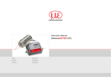
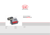
The OS-PC is a non-contact temperature sensor with built-in LED sighting. It has an extremely
fast response time, and can measure a spot as small as 1.6 mm in diameter.
The continuous LED sighting illuminates the position and size of the measurement spot while
readings are being taken, without affecting the accuracy of the measurement.
The sensor works by detecting the infrared radiation emitted from a surface as a result of its
own temperature. The amount of radiation emitted is related to the temperature, and the
sensor uses this relationship to provide an accurate temperature measurement.
OS-PC sensors are ideal for measuring the surface temperature of paper, thick plastics, food,
rubber, electronic components, cable, ceramics, textiles, painted surfaces and some metals,
as well as many other materials.
OS-PC-TSD
The OS-PC-TSD is an optional multilingual touch screen interface module for the OS-PC
sensor. It functions as a standalone temperature indicator, alarm unit and configuration tool,
and a selectable analogue output allows it to be connected to further instrumentation.
All the settings of the OS-PC sensor are adjustable via the built-in touch screen interface.
When an optional MicroSD Card is inserted into the OS-PC-TSD, the system functions as a
fully-configurable temperature data logger.
OS-PC Sensor Specifications
Measurement
Temperature Range
0°C to 500°C
Response time (95
% of step
change)
-S models: 10 ms to 5 s
-F models: 1 ms to 5 s
Adjustable via averaging function
Target sighting
Red LED built-in as standard on all models. Indicates the
measured spot size. Switchable on/off.
Measurement Accuracy*
-S models: ± 3°C or 1%, whichever is greater
-F models: ± 3.5°C or 1%, whichever is greater
Repeatability*
-S models: ± 0.5°C
-F models: ± 1°C
Resolution*
-S models: < 0.5°C
-F models: < 1.5°C (0 to 50°C); < 0.7°C (above 50°C)

Measurement (continued)
Emissivity setting
Adjustable 0.3 to 1.0 via RS232C or optional touch
screen interface
Optics
See Field of View Diagrams
* Ambient temp. 23 ± 5°C, emissivity 1.0, averaging time 0.05 s
Electrical
Outputs
1 analogue output and 1 alarm output
Analogue output
4-20 mA (set by default), 0-20 mA, mV/°C or
voltage‡, selectable via optional touch screen interface.
Alarm output
1 open drain alarm output, rated 27 V DC, 0.2 A
Supply voltage
5 to 27 V DC, 100 mA max
Digital Communications
RS232C Modbus RTU, non-isolated
‡ Voltage can be 0-1, 0-5, or 0-10 V DC, depending on model (see Model Numbers).
Mechanical
Weight (without cable)
85 g
Environmental
Environmental rating
IP67
Operating ambient
temperature
0°C to 50°C
Storage temperature
-15°C to 70°C
Operating ambient humidity
30% to 85% RH non condensing
Display
Display Optional OS-PC-TSD touch screen interface module for
indication, configuration, data logging and alarm outputs

Electromagnetic Compatibility Standards
EMC Directive EN61326-1:2013
CISPR 11:2009 Industrial and scientific equipment – Emissions test
IEC61000-4-2 Electrostatic Discharge Immunity
IEC61000-4-3 Electromagnetic Field Immunity
IEC61000-4-4 Burst Immunity
IEC61000-4-5 Surge Immunity
IEC61000-4-6 Conducted RF Immunity
OS-PC-TSD Touch Screen Interface Module Specifications
Interface
Display Format
2.83" (72 mm) resistive touch TFT, 320x240 pixels,
backlit
Configurable Parameters
Language (English, Chinese, Japanese)
Temperature units
Displayed temperature (instantaneous, hold)
LED sighting on/off
Password
Date & time (for data logging time stamps)
Peak hold period, discharge level
Averaging period
Correction (gain/offset)
Emissivity setting (with teach function)
Reflected energy compensation (with teach function)
Output type
Output temperature range
Polarity on error
Alarm mode, levels, hysteresis

Data Logging
Storage
MicroSD Card (optional), max. 32 GB, equal to 16 years
of data at the fastest sample rate of 1 per second
Sample Interval
1 second to 1 day (configurable)
Internal Clock Battery
1 x BR 1225, 3 V (not included)
Variables Logged
Unfiltered temperature, hold temperature, alarm events
Configurable Parameters
Data logging:
Sample period
Number of samples
Scheduled start
Alarm logging:
Log times when triggered,
acknowledged, reset
Log data while triggered
Outputs
Outputs
2 x alarm relay outputs rated 24 V DC, 1 A;
Retransmitted analogue output from sensor
Retransmitted Analogue Outputs
Output Type
Effective Minimum Output
Output Accuracy (additional to
Measurement Accuracy)
0
to
1
V DC
30 mV ±1.5 mV
mV/°C
30 mV ±1.5 mV
0
to
20
mA
0.2 mA ±0.02 mA
4
to
20
mA
4.0 mA ±0.02 mA

Model Numbers
OS-PC Sensor
OS-PC 16 - 2M - 1V
Voltage output option
1V = 0 to 1 V DC
5V = 0 to 5 V DC
10V = 0 to 10 V DC
Note: All models also have 0-20
mA, 4-20 mA, and mV/°C outputs
as standard.
Cable length
2M = 2 metres
5M = 5 metres
10M = 10 metres
Field of view and response time
16 = 10 ms response, 1.6 mm spot at 35 mm distance
30 = 10 ms response, 3.0 mm spot at 70 mm distance
55 = 10 ms response, 5.5 mm spot at 120 mm distance
F35 = 1 ms response, 3.5 mm spot at 100 mm distance
F70 = 1 ms response, 7.0 mm spot at 200 mm distance
Series
PCU = OS-PC sensor
OS-PC-TSD Touch Screen Interface Module
OS-PC-TSD Touch screen interface module for OS-PC sensor

Field of View
Diagrams
Diagrams show the diameter of the
measured spot at each distance, for 90%
energy. The accuracy specifications for the
PyroCube sensor are valid up to the
maximum distances shown.
Emissivity Adjustment
The default emissivity setting is 0.95. It may be adjusted in two ways via the touch screen
interface:
Settings
Input Settings
Emissivity & Compensation
Emissivity & Compensation
Settings
Enter the target emissivity here. For help with finding the target emissivity, contact Omega.
Settings
Input Settings
Emissivity & Compensation
Teach Emissivity
Measure the true surface temperature using another device, such as a trusted contact
thermometer. Enter the true temperature here, and the sensor calculates the correct emissivity
setting.
To use this function, the target temperature must be greater than 50°C.

Reflected Energy Compensation
Settings
Input Settings
Emissivity & Compensation
Emissivity & Compensation
Settings
Some of the infrared energy detected by an infrared temperature sensor is not emitted by the
target, but is a reflection of its surroundings.
To ensure an accurate reading, the sensor needs to know the temperature of the source of
that reflected energy. In most applications, the surroundings of the target have the same
temperature as the sensor itself (e.g. the sensor and target are in the same room). The sensor
automatically compensates for the reflected energy, so Reflected Energy Compensation is not
required.
However, in some applications, the source of the reflected energy (the surroundings of the
target) is much hotter or colder than the sensor itself. In these cases, Reflected Energy
Compensation should be enabled.
For example, if the target is inside a furnace and the sensor is outside, the reflected energy is
coming from the inner walls of the furnace. Use the Teach Reflected Temperature function to
find the correct setting. Enter the true target temperature and the sensor will compensate for
the reflected energy.
For assistance, contact Omega.
Alarm Outputs
When used without the optional OS-PC-TSD interface module, the sensor has one open drain
alarm output, configurable via RS232C Modbus. The output is rated 27 V DC, 0.2 A.
The OS-PC-TSD has two individually-configurable alarm relay outputs. These are rated
24 V DC, 1 A. These are individually configurable via the touch screen interface.
Each alarm has two set point temperatures (Low and High). The behaviour of the alarm
depends on the Alarm Mode.
Alarm Mode
Low Measured Temperature High
Low Set Point High Set Point
High On
ALARM ON
High Off
ALARM ON
Low On
ALARM ON
Low Off
ALARM ON
Band On
ALARM ON
Band Off
ALARM ON
ALARM ON
Error On
ALARM ON
Error
Off
For “Error On” and Error Off” alarms, the alarm monitors for an internal voltage abnormality. In

the event of such an error, an “Error On” alarm will be ON and an “Error Off” alarm will be OFF.
OS-PC-TSD Touch Screen Interface Module
The backlit touch screen interface module provides a large, bright display of the measured
temperature, two alarm relay outputs, and options for full configuration of the sensor.
The graph view shows the history of the measured temperature. In alarm conditions, the
display changes colour to provide an immediate and obvious alarm indication. Alarm modes
and levels can be configured via the touch screen.
OS-PC-TSD Interface Functions
Main Screen
(Temperature
View)
Displays a large indication of the measured temperature. The
background turns bright red when an alarm is activated.
MicroSD Card Status
This icon is displayed when a MicroSD card is inserted, and
flashes when data logging is in progress.
Scheduled Logging
This icon is displayed when scheduled data logging is
enabled and has yet to begin.
Temperature Units °C and °F
Press “°C” to switch to °F and vice versa. The units are
changed throughout the interface.
Display Options
Press the measured temperature to select which reading is
shown:
Hold Temperature: The measured temperature,
with averaging and hold processing.
Unfiltered Temperature: The unprocessed
measured temperature.
Sighting On/Off
Switches the LED sighting light on or off. The light does not
affect the measurement accuracy.
Start/Stop Logging
Manually begins or ends data logging (requires MicroSD
Card, available separately).
If Scheduled Start is enabled in Settings > Data Logging,
then logging cannot be started manually.
To manually start logging, you must first disable Scheduled
Start.

Acknowledge Alarms
Switches the relay outputs for triggered alarms to their
normal, untriggered state. The background of the
Temperature View and Graph screen will stay red, and the
alarms will not be triggered again until they are reset (see
“Alarms” below). Alarms can be acknowledged while the
display is locked.
L
ock/Unlock
Prevents settings being changed via a four-digit numerical code.
To unlock the sensor, enter the password and press the Unlock icon.
The default password is 1234.
Change Password
Enter, confirm and save a new four-digit code.
Graph
Displays the recent history of the Filtered Temperature and the Sensor
Temperature. To scroll backwards and forwards in time, touch the graph
and drag it. The graph stores the most recent 24 hours of temperature
data.
Reset Graph
Clears and restarts the graph.
Return to Scrolling View
Returns the graph to the real-time scrolling view, showing
the most recent measurements.
Settings
Access the configuration parameters. Press Apply to save the settings,
or Exit to leave the screen without saving.
Default Settings
Reset all settings to factory defaults.
Settings
Input Settings
These settings affect the sensor and the measured temperature.

Output Settings
These settings affect the OS-PC-TSD’s analogue retransmission output,
and the alarm relays.
Date & Time
Change the date and time for data logging purposes.
The clock is reset when the power is switched off, unless a battery is
fitted.
Data Logging
Configure the storage of temperature data and alarm events. A MicroSD
Card (optional) must be inserted to use these features.
Language
Change the language of the interface. Select from English, Japanese
and Simplified Chinese.
Settings
Input Settings
Emissivity & Compensation
Emissivity & Compensation Settings
Emissivity Setting
Enter the emissivity of the target surface. The emissivity setting
should match the target emissivity for maximum accuracy.
Enable Reflected Energy Compensation
Select to enable Reflected Energy Compensation, which
improves the measurement accuracy if there is significant
reflected energy, for example when measuring an object inside
a furnace with the sensor positioned outside.
In most applications, this setting should be disabled.
For more information, see the “Reflected Energy
Compensation” section of this guide.
Reflected Value
If reflected energy compensation is required, enter the
temperature of the surroundings of the target here.
Teach Emissivity
Enter the true temperature of the target here, and the sensor will
automatically determine the emissivity setting. For more information, see
the “Emissivity Adjustment” section of this guide.

Teach Reflection Value
Enter the true temperature of the target here, and the sensor will
automatically compensate for reflected energy. For more information, see
the “Reflected Energy Compensation” section of this guide.
Settings
Input Settings
Peak Hold
With Peak Hold, the sensor will continue to display or output a peak
in the measured temperature for a certain time. This feature is ideal
for monitoring the temperature of individual objects on a conveyor,
and for ignoring unwanted low readings, such as when a rotating
stirring arm in a container of liquid passes the sensor.
Reset
The peak hold mode. Choose from Time or Discharge:
Time
The output returns instantly to the measured temperature
after the Reset/Discharge Time.
Discharge
The output decreases steadily after a peak. The rate of
decay depends on the Reset/Discharge Time and the
Discharge Level.
Reset/Discharge Time
The peak hold period. This depends on the “Reset” setting.
Discharge Level
In “Discharge” mode, this is the percentage of the measured
temperature that the peak hold temperature will reach after the

Reset/Discharge Time has elapsed.
Discharge Level has no effect when “Time” mode is enabled.
Peak Hold Off/On
Enable or disable peak hold processing.
Averaging
Select the required averaging period to smooth the output and slow down the
sensor’s response time. The default setting is 50 ms.
Note: averaging prevents the sensor from following rapid temperature
changes.
Correction
Correction Span
Adjusts the gain (slope) of the sensor’s measured temperature
response. For example, this can be used when measuring through a
window to correct for transmission loss.
The sensor is calibrated in the factory with Correction Span set at
1.000 and this setting should not normally be adjusted.
Note: When Correction Span is set lower than 0.9, the upper limit of
the temperature range is reduced below the published specification.
Correction Offset
This value is added to the measured temperature.
Settings
Output Settings
Output Type
Select the analogue output type:
4-20 mA - this is the default setting.
0-20 mA
Voltage - the output voltage range is 0-1, 0-5, or 0-10 V DC
depending on the model.
mV/°C
No output – disable the analogue output.

Output Range
Re-scale the Lower Limit and Upper Limit of the full range of
the analogue output. The output is linear between these
temperatures.
e.g. 4 mA output at 0°C; 20 mA output at 500°C.
Output Temperature.
Select whether the hold processing settings should be applied to the
output temperature.
Unfiltered Temperature
No processing is applied to the output temperature. The raw
measured signal is output from the sensor.
Hold Temperature
The peak hold function is applied to the output temperature.
Note: This function is independent from the displayed
temperature (see Display Options near the beginning of this
table).
Polarity on Error
Determines whether the sensor output will default to the upper or lower
limit in a fault condition (internal voltage abnormality).
Untreated
In a fault condition, the sensor will not change output
behaviour.
Upper Limit
In a fault condition, the sensor will default to the upper output
limit.
Lower Limit
In a fault condition, the sensor will default to the lower output
limit.
Settings
Output Settings
Alarms
Alarms
The settings for the Alarm 1 and Alarm 2 relay outputs are
configured individually.
Al
arm Mode
High On - The alarm is active above the Alarm High temperature.
High Off - The alarm is active below the Alarm High temperature.
Low On - The alarm is active below the Alarm Low temperature.
Low Off - The alarm is active above the Alarm Low temperature.
Band On - The alarm is on between the Alarm Low and High
temperatures.

Band Off
-
The alarm is on below the Alarm Low temperature and
above the Alarm High temperature.
Error On - The alarm is active in a fault condition (internal voltage
error).
Error Off - The alarm is active in a normal (non-fault) condition.
For more information, see the section “Alarm Outputs”.
Alarm Settings
Alarm Low
Alarm High
Each alarm has two temperature set points: High and Low.
Depending on the Alarm Mode, either one or both of these set points
will be used to activate the alarm.
Hysteresis
Example: High On alarm with Hysteresis
Hysteresis is the temperature difference between “alarm on” and
“alarm off”. It is a band centred on the alarm setpoint temperature.
The value of Hysteresis is the size of this temperature band.
Settings
Data Logging
Data Logging Settings
Sample period
The time, in seconds, between samples.
Number of samples
The number of samples the unit will collect before logging
stops. Enter “0” to log data continuously until manually stopped.
Enable Scheduled Start
The sensor begins logging at the Date and Time specified.
Logging can also be started and stopped manually.
Date and Time
The date and time for scheduled logging to start.

Ala
rm Logging Settings
Alarm events can be logged to the MicroSD Card. Alarm log files and
settings are independent from Data Logging.
Log Trigger Time
The time that an alarm is triggered will be logged.
Log While Triggered
Data logging will start when an alarm is triggered. 1 sample is
logged per second. Logging stops when both alarms are reset.
Log Acknowledge Time
The time that the alarm is acknowledged will be logged.
Log Reset Time
The time that the alarm is reset will be logged.
Data Logging Specifications
The OS-PC and OS-PC-TSD can be used as a standalone data logger. Data logging can be
configured via the touch screen interface.
Data is stored on a MicroSD card in .csv format and can be viewed and edited easily using
spreadsheet software. The MicroSD card is available as an optional accessory, with an SD
Card adapter to transfer data to a PC.
With a 2 GB card, the user can store 28.4 million readings, which is almost 1 year’s worth of
data at 1 sample per second. Larger cards provide more storage.
The MicroSD card slot and battery holder are located on the touch screen circuit board in the
lid of the OS-PC-TSD. Readings are time and date stamped using the unit’s internal clock.
The clock is reset when the power is disconnected, or it will continue if the optional battery is
fitted.
Using the OS-PC-TSD as a Data Logger
1. Insert a MicroSD card into the holder on the circuit board inside the lid of the OS-PC-TSD.
2. To retain the date and time when the unit is switched off, fit a battery to the holder on the
circuit board inside the lid.
3. Replace the lid and connect the sensor power supply.
4. To set the number of samples to be logged, the time period between samples, and, if
required, to schedule data logging to automatically start, press to access the Settings
menu, then press to access the Data Logging options.

5. To save data logging settings, press
6. To manually start data logging, press on the Temperature View.
7. While logging is in progress, the logging icon flashes on the Temperature View.
8. To stop data logging, press
9. To transfer data to a computer, remove the MicroSD Card from the unit, insert the card into
the SD Card adapter (supplied with the MicroSD Card, accessory model MSD) and insert the
adapter into an SD Card reader.
Installation of MicroSD Card and Battery
The MicroSD Card and battery slots are located on the touch screen circuit board. Unscrew
the lid of the OS-PC-TSD to access them.
The battery is optional. With a battery fitted, the internal clock will continue to run when the
power is off. Without a battery, the unit will request the date and time each time the power is
cycled.
All other settings are stored in permanent memory and will be preserved when it is switched
off, regardless of whether a battery is fitted.
Data Log Files
Data is saved to the MicroSD Card in .csv format. This file format can be opened or imported
by spreadsheet software such as Microsoft Excel.
A new folder is created on the MicroSD Card for each day that data is logged.
A new log file is created every time logging is started. The start time is used as the file name.

Sensor Dimensions

OS-PC-TSD Dimensions

Accessories All dimensions in mm
Mounting Bracket
Provides a sturdy mount for the sensor and allows rotation about
one axis.
Thickness: 2.0 mm. Weight: 45 g.
Air Purge Collar
Helps prevent dust and condensation from settling on
the lens.
Use clean (instrument) air. Maximum flow rate: 5 l/min,
maximum pressure 0.2 MPa.
OS-PC-APC (for OS-PC models)
Page is loading ...
Page is loading ...
Page is loading ...
Page is loading ...
Page is loading ...
Page is loading ...
Page is loading ...
Page is loading ...
Page is loading ...
Page is loading ...
Page is loading ...
Page is loading ...
Page is loading ...
Page is loading ...
Page is loading ...
Page is loading ...
Page is loading ...
Page is loading ...
Page is loading ...
Page is loading ...
/