Page is loading ...

VP-2117 Getting Started, Apr. 2010, V1.0
1
Getting Started: VP-2117
By ICP DAS CO., LTD., 2010, All Rights Reserved
ICP DAS CO., LTD. would like to congratulate you own your purchase of our
ISaGRAF PACs - VP-2117. The ease to integration of the controller system and
the power of the IEC 61131-3 ISaGRAF software program combine to make a
powerful, yet inexpensive industrial process control system.
ISaGRAF PAC Series of ICP DAS includes :
PAC: PAC-7186EG, PAC-7186PEG , I-7188EG, I-7188XG,
iPAC: iP-8447, iP-8847, I-8437-80, I-8837-80, I-8417, I-8817,
WinPAC: WP-8147, WP-8447, WP-8847 (WinCon: W-8347, W-8747)
ViewPAC: VP-2117, VP-2xW7
Legal Liability
ICP DAS CO., LTD. assumes no liability for any and all damages that may be
incurred by the user as a consequence of this product. ICP DAS CO., LTD.
reserves the right to change this manual at any time without notice.
ICP DAS CO., LTD. constantly strives to provide our customers with the most
reliable and accurate information possible regarding our products. However, ICP
DAS CO., LTD. assumes no responsibility for its use, or for any infringements of
patents or other rights of third parties resulting from its use.
Trademark & Copyright Notice
The names of products are used for identification purposes only, and are the
registered trademarks of their respective owners or companies.
Technical Service
Please contact local agent or email problem-report to service@icpdas.com .
New information can be found at www.icpdas.com.
Please visit www.icpdas.com FAQ Software ISaGRAF for Frequently
Asked Questions.
Written by Chun Tsai, Spike Huang ; Edited by Janice Hong.
Copyright © 2010 by ICP DAS CO., LTD. All Rights Reserved.

VP-2117 Getting Started, Apr. 2010, V1.0
2
Table of Contents
Getting Started: VP-2117 ....................................................................................................... 1
Legal Liability ................................................................................................................. 1
Trademark & Copyright Notice ....................................................................................... 1
Technical Service ........................................................................................................... 1
Table of Contents ................................................................................................................... 2
Reference Guide .................................................................................................................... 4
Performance Comparison Table of ISaGRAF PACs ........................................................... 5
Specifications: VP-2117 ......................................................................................................... 6
Chapter 1 Typical Application ........................................................................................ 1-1
1.1 Appearance ......................................................................................................... 1-1
1.2 Multi-HMI & Local/Remote I/O............................................................................. 1-2
1.3 Redundant Bus7000 ........................................................................................... 1-2
1.4 Data Exchange through Ethernet & RS-485 ....................................................... 1-3
1.5 Active Control Data and I/O Acquisition Data Reporting System ........................ 1-3
1.6 Constructions Monitoring Application (VW Sensor) ............................................. 1-4
1.7 Modbus Converter of I-7000 & I-87K I/O ............................................................. 1-4
1.8 Motion Control ..................................................................................................... 1-5
1.9 SMS: Short Message Service ............................................................................. 1-5
1.10 Modbus Master ................................................................................................... 1-6
1.11 Send Email with One Attached File ..................................................................... 1-7
1.12 Integrate with CAN/CANopen Devices and Sensors ........................................... 1-7
1.13 Fast FRnet Remote I/O ....................................................................................... 1-8
1.14 ZigBee Wireless Solution .................................................................................... 1-9
Chapter 2 Installing Software ......................................................................................... 2-1
2.1 Step 1 - Installing the ISaGRAF Software ........................................................... 2-1
2.1.1 The hardware protection device (dongle & USB Key-Pro) ........................... 2-2
2.1.2 Important Notice for Window 2000 Users:.................................................... 2-3
2.1.3 Important Notice for Window NT Users ........................................................ 2-3
2.2 Step 2 - Installing the ICP DAS Utilities for ISaGRAF ......................................... 2-4
Chapter 3 Hardware System & Setting .......................................................................... 3-1
3.1 Setting the NET-ID for the VP-2117 .................................................................... 3-1
3.2 Connecting PC to the VP-2117‟s COM1 ............................................................. 3-2
3.3 Connecting PC to VP-2117‟s COM2 ................................................................... 3-3
3.4 Connecting PC to Several VP-2117‟s COM2 ...................................................... 3-3
3.5 Setup COM Port‟s Baud rate & Non- Modbus Slave Port from PAC ................... 3-4
3.6 Deleting an ISaGRAF Project from the Controller ............................................... 3-6
3.7 Connecting PC to the VP-2117 Ethernet Port ..................................................... 3-7
3.8 Modbus Slave Connection to the VP-2117 ......................................................... 3-9
3.9 Setting VP-2117‟s IP & MASK & Gateway ........................................................ 3-10
3.10 Update VP-2117‟s Hardware Driver .................................................................. 3-12
3.11 Backup & Restore an ISaGRAF Project ............................................................ 3-14

VP-2117 Getting Started, Apr. 2010, V1.0
3
3.12 The connection mode of Fbus ........................................................................... 3-15
3.13 Setting I-7000 and I-87K Remote I/O by DCON Utility ...................................... 3-15
3.14 Linking I-7000 and I-87K Modules for Remote I/O ............................................ 3-19
3.15 Creating a Modbus Link with the PAC ............................................................... 3-20
3.16 Linking To an MMI Interface Device .................................................................. 3-21
3.17 Using N-Port COM ............................................................................................ 3-22
3.18 Pin Assignment of Communication Ports .......................................................... 3-23
3.19 Dimension ......................................................................................................... 3-24
Chapter 4 Show String on the VP-2117’s LCD .............................................................. 4-1
4.1 Writing a Simple ISaGRAF Program ................................................................... 4-1
4.1.1 Open ISaGRAF-Project Management .......................................................... 4-2
4.1.2 Creating An ISaGRAF User‟s Group ............................................................ 4-2
4.1.3 Creating a New ISaGRAF Project ................................................................ 4-2
4.1.4 Declaring the ISaGRAF Project Variables.................................................... 4-3
4.1.5 Create the LD - “LD1” Program.................................................................... 4-8
4.1.6 Edit the “LD1” Program ................................................................................ 4-9
4.1.7 Connecting the I/O ..................................................................................... 4-14
4.2 Compiling & Simulating the Example Project .................................................... 4-15
4.3 Download & Debug the Example Project .......................................................... 4-18
Appendix ................................................................................................................................. 1
A. ISaGRAF User Manual & Demo Program & FAQ ...................................................... 1
A.1 The Download Page for ISaGRAF Resource .................................................... 1
A.2 Using Modbus TCP/IP protocol to control ISaGRAF controllers with VB? .......... 2
B. How to Detect the Status of “Hot Swap” for I-87K ..................................................... 3
C. How to Detect the Status of Dual Battery .................................................................. 4
D. 10-ch Thermocouple Input Module ............................................................................ 5
D-1: I-7018Z ............................................................................................................... 5
D-2: I-87018Z ............................................................................................................. 5
Advantages .................................................................................................................... 5
E. RU-87P1/2/4/8 ........................................................................................................... 6

VP-2117 Getting Started, Apr. 2010, V1.0
4
Reference Guide
ISaGRAF Web Information:
http://www.icpdas.com/products/PAC/i-8000/isagraf.htm or
www.icpdas.com > Products > Software > ISaGRAF
ISaGRAF User’s Manual:
CD-ROM: \napdos\isagraf\8000\english_manu\ user_manual_i_8xx7.pdf
http://www.icpdas.com/products/PAC/i-8000/getting_started_manual.htm
ISaGRAF (Chinese) User’s Manual:
CD-ROM: \napdos\isagraf\8000\chinese_manu\chinese_user_manual_i_8xx7.pdf
http://www.icpdas.com/products/PAC/i-8000/getting_started_manual.htm
Hardware Manual:
Please refer to CD-ROM:
\NAPDOS\vp-2000\document\vp_2111_user_manual_v1.01.pdf
http://ftp.icpdas.com.tw/pub/cd/8000cd/napdos/vp-2000/document/vp_2111_user_
manual_v1.01.pdf
Resource on the Internet:
Newly updated ISaGRAF IO libraries, drivers and manuals can be found at
http://www.icpdas.com/products/PAC/i-8000/isagraf.htm
Related Products:
Industrial Ethernet Switch: NS-205/NS-208
http://www.icpdas.com > Products > Industrial Ethernet
Switch > Unmanaged Industrial Ethernet Switch
RS-232 to RS-422/485 Converter : I-7520R
http://www.icpdas.com > Products > Industrial
Communcation > Converter & Repeater
Power Supply : DP-665/660, KA-52F
http://www.icpdas.com > Products > Accessories >
Power_Supply
High profile I-8K/87K Series I/O Modules
http://www.icpdas.com/products/PAC/i-8000/io_support_list.htm
FAQ:
Please visit www.icpdas.com FAQ Software ISaGRAF for Frequently
Asked Question, or visit http://www.icpdas.com/faq/isagraf.htm


VP-2117 Getting Started, Apr. 2010, V1.0
6
Specifications: VP-2117
System Software
OS
MiniOS7 (DOS-like embedded operating system)
Development Software
ISaGRAF Version 3
IEC 61131-3 standard. Languages: LD, ST, FBD, SFC, IL &
FC
Max. Code Size
Accepts max. 64 KB ISaGRAF code size
(Appli.x8m must < 64 KB)
Power Supply
Power Input
+10 ~ +30 VDC
Isolated
1 kV
Redundant Power
Inputs
Yes, with one power relay (1 A @ 24 VDC) for alarm
Capacity
3A, 5V supply to I/O expansion slots
Consumption
6 W (0.25 A @ 24 V)
General Environment
Temperature
Operating: -15 ~ +55 °C Storage : -30 ~ +80 °C
Humidity
10 ~ 90 % RH (non-condensing)
System
CPU
80186 (80 MHz and 16-bit) or compatible
SRAM
768 KB
Dual Battery
Backup SRAM
512 KB (for 5 years data retention), support up to 1024 retain
variables
Flash
512 KB (100,000 erase/write cycles)
Flash Disk
64 MB NAND Flash (100,000 erase/write cycles)
NVRAM
31 bytes (battery backup, data valid up to 5 year)
EEPROM
16 KB
(data retention > 40 years ; 1,000,000 erase/write cycles)
Watchdog Timer
Yes, Default=0.8s
RTC (Real Time Clock)
Provide second, minute, hour, date, day of week, month, year
Serial Number
64-bit hardware serial
(The user can add a check mechanism to protect program);
Communication Interface
Ethernet
RJ-45*1, 10/100 Base-TX, (Auto-negotiating, LED
indicators), program download port.
COM0
Internal communication with the I-87K High Profile modules
in slot 0 ~ 2.
COM1
RS-232: TxD, RxD, GND, Speed: 115200 bps max. Program
downloads port.
COM2
RS-485: D+, D- ; Speed: 115200 bps max.
2500 VDC isolated.
COM3
RS-232/RS-485,
RS-232:TxD,RxD,GND,CTS,RTS ; RS-485:DATA+,DATA-,

VP-2117 Getting Started, Apr. 2010, V1.0
7
Speed: 115200 bps max. Program downloads port.
I/O Expansion Slots
Slots Number
3 (For High Profile I-8K and I-87K Modules only)
Hot Swap
Yes (For High Profile I-87K Modules Only)
Data Bus
8/16 Bits
Address Bus Range
2 K for each slot
MMI (Man Machine Interface)
LCD Type and Size
STN, 128x64 Dot Matrix LCD
Text Font
English + Simplified Chinese (VP-2117) or
English + Traditional Chinese (VP-2117-TC)
Display Mode
Text + Graphics
Rubber Keypad
24 keys
Buzzer
Yes
LED Indicators
3 Dual-Color LEDs (PWR, RUN, LAN1, L1, L2, L3; L1~L3 for
User Programmable)
Mechanical
Dimensions (W x L x H)
182 mm x 158 mm x 125 mm
Ingress Protection
Front panel: IP65
Motion Control
one I-8091W (2-axis) or two I-8091W (4-axis) to do motion control. Ethernet
communication is also available when doing motion control.
PWM Output
High Speed PWM
Module
I-8088W: 8-ch PWM outputs, software support 1 Hz ~ 100
KHz (non-continuous), duty: 0.1 ~ 99.9%
DO Module as PWM
8-ch max. for one controller. 500 Hz max. for Off=1 & On=1
ms Output square wave: Off: 1 ~ 32767 ms, On: 1 ~ 32767
ms. Optional DO boards: I-8037W, 8041W, 8041AW, 8042W,
8050W, 8054W, 8055W, 8056W, 8057W, 8060W, 8063W,
8064W, 8068W, 8069W
(Relay Output boards can not generate fast square pulse)
Counters , Encoder, Frequency
Parallel DI Counter
8-ch max. for 1 controller. Counter Val: 32-bit. 500 Hz max.
Min. ON & OFF width must >1ms. Optional DI boards:
I-8040W, 8040PW, 8042W, 8050W, 8051W, 8052W, 8053W,
8053PW, 8054W, 8055W, 8058W, 8063W.
Serial DI Counter
Counter input: 100 Hz max. Counter value: 0 ~ 65535 (16-bit)
Optional serial I-87K DI boards: I-87040W, 87046W,
87051W, 87052W, 87053W, 87053W-A5, 87054W, 87055W,
87058W, 87059W, 87063W
Remote DI Counter
All I-7000 & I-87K DI modules support counters.
100 Hz max. value: 0 ~ 65535
High Speed Counter
I-87082W: 100 kHz max. 32-bit,
I-8084W: 250 kHz max. 32-bit
Encoder
I-8093W : 3-axis Encoder Module, max. 1M Hz for quadrant
input mode, max. 4M Hz for pulse/direction and cw/ccw input

VP-2117 Getting Started, Apr. 2010, V1.0
8
mode. (FAQ-112)
I-8084W: 250 kHz max. , 4-ch encoder, can be
Pulse/direction, or Up/Down or A/B phase (Quad. mode); Not
support Encoder Z-index. (FAQ-100)
Frequency
I-87082W: 2-ch, 1 Hz ~ 100 kHz;
I-8084W: 8-ch, 1 Hz ~ 250 kHz;
Protocols
Modbus Master
Protocol
Up to 2 COM Ports ; COM1 ~ 3 & (COM5 in multi serial port
board) can support Modbus RTU Master or ASCII Master
protocol to connect to other Modbus Slave devices, 2 ports
support up to 128 Modbus_xxx function blocks (same type).
Modbus Slave Protocol
Up to 2 COM Ports, COM1 and one of (COM2, COM3) can
support Modbus RTU Slave protocol for connecting
ISaGRAF, PC/HMI/OPC Server & MMI panels.
Modbus TCP/IP
Protocol
Support Modbus TCP/IP Slave protocol for connecting
ISaGRAF & PC/HMI. (Max. 6 connections)
Remote I/O
One of COM2, 3 supports I-7000 I/O modules & (I-87K base
or RU-87P1/2/4/8) + I-87K High Profile I/O cards as Remote
I/O. Max. 64 Remote I/O module for one controller
Fbus
Built-in COM3 Port to exchange data between ICP DAS‟s
ISaGRAF PACs.
Ebus
To exchange data between ICP DAS‟s ISaGRAF Ethernet
PACs via Ethernet Port.
SMS:
Short Message Service
One of COM3 or ( COM5 in multi serial port board) can link to
a GSM Modem to support SMS. User can request data/
control the controller by cellular phone. The controller can
also send data & alarms to user‟s cellular phone. Optional
GSM Modem: GTM-201-RS232 ( 850/900/1800/1900
GSM/GPRS External Modem) or visit to
http://www.icpdas.com/products/
GSM_GPRS/wireless/GSM_GPRS_modem.htm for
recommended GSM/GPRS Modem
User Defined Protocol
User can write his own protocol applied at COM1 ~ COM3 (&
COM5 ~ COM16 if multi-serial port boards are plugged) by
serial communication function blocks.
CAN/CANopen
Up to 3 COM Port. User can use its COM1, 3, or (COM5 ~
COM12, resides at the I-8112iW/8114W/8114iW RS-232
expansion board) to connect one I-7530 (RS-232 to CAN
converter) to support CAN/CANopen devices and sensors.
One VP-2117 supports max. 3 RS-232 Ports to connect max.
3 I-7530. Please refer to www.icpdas.com > FAQ > Software
> ISaGRAF Ver.3 (English) > FAQ-086.
FRnet I/O
Support max. 3 I-8172W FRnet Master cards to connect
FRnet I/O modules. (max. 768-ch D/I + 768-ch D/O)
Sending E-Mail
Actively or passively sending E-mail via Ethernet Port through
internet. Max. 10 receivers for each sending and can send
E-mail with an attached file (Max. file size is about 488 KB).

VP-2117 Getting Started, Apr. 2010, V1.0
1-1
Chapter 1 Typical Application
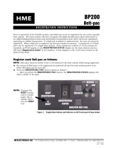
1.1 Appearance
VP-2117 is the ISaGRAF PAC with graphic display and keypad.
Features:
80186, 80 MHz CPU (16 bits)
Large SRAM: 768 KB
512 KB FLASH Memory
64 MB NAND Flash for Data Storage
Dual Battery Backup SRAM (512 KB)
Hot-Swap High Profile I-87K I/O Ability
64-bit Hardware Serial Number for
Software Protection
IP65 Compliant Front Panel
MMI (Man Machine Interface)
STN, 128 x 64 Dot Matrix LCD
English + Simplified Chinese or
English + Traditional Chinese Fonts
Text and Graphics Display Mode
Rubber Keypad with 24 Keys
Buzzer : Yes
3 Dual-Color LED Indicators
(PWR, RUN, LAN1, L1, L2, L3;
L1 ~ L3 for User Programmable)
Note: VP-2117 only support I-8K, I-87K High Profile I/O modules plugged on slot
0 ~ 2.

VP-2117 Getting Started, Apr. 2010, V1.0
1-2
1.2 Multi-HMI & Local/Remote I/O
Users can choose RS-485 Remote I/O modules (I/7000, M-7000) or expansion
units (RU-87Pn, I-87Kn) plugged with I-87K high profile I/O modules. With Modbus
TCP/IP protocol, up to 6 PCs can link to one VP-2117.
1.3 Redundant Bus7000

VP-2117 Getting Started, Apr. 2010, V1.0
1-3
1.4 Data Exchange through Ethernet & RS-485
VP-2117 can support Ebus (Ethernet) and Fbus (RS-485)
1.5 Active Control Data and I/O Acquisition Data Reporting System
For more information, please refer to www.icpdas.com > FAQ > Software >
ISaGRAF Ver.3 (English) > FAQ-065

VP-2117 Getting Started, Apr. 2010, V1.0
1-4
1.6 Constructions Monitoring Application (VW Sensor)
For more information, please refer to www.icpdas.com > FAQ > Software >
ISaGRAF Ver.3 (English) > FAQ-091
1.7 Modbus Converter of I-7000 & I-87K I/O
VP-2117 can be a Modbus RTU serial & TCP/IP converter of I-7000 & I-87K
Remote I/O modules.

VP-2117 Getting Started, Apr. 2010, V1.0
1-5
1.8 Motion Control
1.9 SMS: Short Message Service
VP-2117 can integrate with a GSM Modem to SMS: Short Message Service. This
allows user to request information or perform control tasks for the ISaGRAF PAC
via his personal cellular phone. In addition, the PAC can also send information and
alarms to user's cellular phone.
One I-8091W can control 2-axis: X-Y plane, or 2-axis independent
Two I-8091W can control 4-axis:
X-Y plane + 2-axis independent or 4-axis independent
Encoder Modules - I-8093W : 3-axis (FAQ-112) ; I-8084W: 4-axis, without
Z-index (FAQ-100) ; I-8090W: 3-axis

VP-2117 Getting Started, Apr. 2010, V1.0
1-6
1.10 Modbus Master
Up to 2 COM Ports (COM1: RS-232, COM2: RS-485, COM3: RS-232/485 and
COM5 in multi serial port board) can support Modbus RTU Master or ASCII Master
Protocol to connect to other Modbus Slave devices.
NOTE:
When the I-8112iW/8114W/8114iW/8142iW/8144iW expansion board plugged,
COM5 ~ COM16 will be added.
http://www.icpdas.com/products/PAC/i-8000/8000_IO_modules.htm

VP-2117 Getting Started, Apr. 2010, V1.0
1-7
1.11 Send Email with One Attached File
For more information, please refer to www.icpdas.com > FAQ > Software >
ISaGRAF Ver.3 (English) > FAQ-067
1.12 Integrate with CAN/CANopen Devices and Sensors
For more information, please refer to www.icpdas.com > FAQ > Software >
ISaGRAF Ver.3 (English) > FAQ-086


VP-2117 Getting Started, Apr. 2010, V1.0
1-9
1.14 ZigBee Wireless Solution
The ISaGRAF PAC plus ZB-2550P and ZB-2551P RS-232/RS-485 Converters can
apply wireless communication, reduce the wiring cost, and achieve the mission of
Remote I/O control and data acquisition.
For more information, please refer to www.icpdas.com > FAQ > Software >
ISaGRAF Ver.3 (English) > FAQ-110


VP-2117 Getting Started, Apr. 2010, V1.0
2-1
Chapter 2 Installing Software
2.1 Step 1 - Installing the ISaGRAF Software
The user needs to install the following two kinds of software before he can program
the VP-2117 controller system. They are
A. ISaGRAF Workbench
B. ICP DAS Utilities for ISaGRAF
User has to purchase at least one pcs. of ISaGRAF Workbench (Ver. 3.4x or Ver.
3.5x ISaGRAF-256-E or ISaGRAF-256-C or ISaGRAF-32-E or ISaGRAF-32-C) to
install on his PC to edit, download, monitor & debug the controller system. Item (B)
is free and it is burned inside the CD-ROM which is delivered with the VP-2117.
Operating system Requirements:
One of the following computer operating systems must be installed on the target
computer system before you can install the ISaGRAF Workbench software
program.
Windows 95 / Windows 98 / Windows 2000
Windows NT Version 3.51 or Windows NT Version 4.0
Windows XP or Vista or Windows 7 (Please refer to
www.icpdas.com > FAQ > Software >ISaGRAF Ver.3 > FAQ117)
Steps to Installing the ISaGRAF Workbench:
Insert the ISaGRAF Workbench CD into your CD-ROM drive. If your computer does
not have the auto-start feature active, use the Windows Explorer and go to the
CD-ROM drive where the Workbench CD is installed, then double-click on the
“install.bat” file listed on the ISaGRAF CD. If the “install.bat” file is not found on
your ISaGRAF CD, then double-click on the “ISaGRAF.exe” file to start the
installation process.
Select the language. Recommend
to use "English" because this
manual uses English version.

VP-2117 Getting Started, Apr. 2010, V1.0
2-2
To begin the ISaGRAF 3.x software program, click on the Windows “Start” button,
then on “Programs”, and you should see the ISaGRAF program group as illustrated
below. You could click “Projects” to start the program.
2.1.1 The hardware protection device (dongle & USB Key-Pro)
You must install the hardware protection device (dongle) provided with the
ISaGRAF software on your computers parallel port to for the ISaGRAF program to
achieve fully authorized functionality. (ISaGRAF-32-E & ISaGRAF-32-C DO NOT
need dongle or USB Key-Pro.)
While using ISaGRAF and the dongle is plugged well, if the “Help” – “About” says
“Maximum number of IO variables: 32”, it means ISaGRAF workbench cannot find
the dongle well. Please reset your PC and then check the “Help” – “About” again. If
it still displays “Maximum number of IO variables: 32”, the driver may not be
installed well. Please do the following steps.
Dongle Protection:
Please execute the ISaGRAF CD_ROM \Sentinel5382\setup.exe for ISaGRAF-80
or \Sentinel\setup.exe for other ISaGRAF version and then reset the PC again.
USB Key-Pro Protection:
1. To make your PC recognize the ISaGRAF USB protection-key, please un-plug
the USB protection-key from your USB port first, then run
“\Sentinel\SSD5411-32bit.exe” in the ISaGRAF 3.55 CD-ROM (or later version)
after you have installed the ISaGRAF. Then please reset your PC.
2. To run ISaGRAF Ver. 3.5x, please always plug the USB protection-key in the
PC‟s USB port.
1.
2.
/