Grizzly G1073 Owner's manual
- Category
- Power tools
- Type
- Owner's manual
This manual is also suitable for

16'' BANDSAW
MODEL G1073/G1073Z
INSTRUCTION MANUAL
COPYRIGHT © 1993 BY GRIZZLY INDUSTRIAL, INC. REG #TX 3 562 349
WARNING: NO PORTION OF THIS MANUAL MAY BE REPRODUCED IN ANY SHAPE
OR FORM WITHOUT THE WRITTEN APPROVAL OF GRIZZLY INDUSTRIAL, INC.
REVISED OCTOBER, 2002. PRINTED IN TAIWAN
ONLINE MANUAL DISCLAIMER
THE INFORMATION IN THIS MANUAL REPRESENTS THE CONFIGURATION OF THE MACHINE AS IT IS CURRENTLY BEING SHIPPED. THE
MACHINE CONFIGURATION CAN CHANGE AS PRODUCT IMPROVEMENTS ARE INCORPORATED. IF YOU OWN AN EARLIER VERSION OF THE
MACHINE, THIS MANUAL MAY NOT EXACTLY DEPICT YOUR MACHINE. CONTACT CUSTOMER SERVICE IF YOU HAVE ANY QUESTIONS
ABOUT DIFFERENCES. PREVIOUS VERSIONS ARE NOT AVAILABLE ONLINE.
G1073
G1073Z

WARNING
Some dust created by power sanding, sawing, grind-
ing, drilling, and other construction activities contains
chemicals known to the State of California to cause
cancer, birth defects or other reproductive harm.
Some examples of these chemicals are:
• Lead from lead-based paints.
• Crystalline silica from bricks, cement, and
other masonry products.
• Arsenic and chromium from chemically treated
lumber.
Your risk from these exposures varies, depending on
how often you do this type of work. To reduce your
exposure to these chemicals: work in a well ventilated
area, and work with approved safety equipment, such
as those dust masks that are specially designed to fil-
ter out microscopic particles.

G1073/G1073Z 16'' Bandsaw -1-
Table Of Contents
PAGE
1. SAFETY ....................................................................................................................2
SAFETY RULES FOR ALL TOOLS..................................................................2-3
ADDITIONAL SAFETY INSTRUCTIONS FOR BANDSAWS ..............................4
2. CIRCUIT REQUIREMENTS ......................................................................................5
220V OPERATION ..............................................................................................5
110V OPERATION ..............................................................................................5
EXTENSION CORDS ..........................................................................................5
GROUNDING ......................................................................................................6
3. GENERAL INFORMATION ......................................................................................7
UNPACKING ........................................................................................................8
PIECE INVENTORY ............................................................................................8
CLEAN UP............................................................................................................9
SITE CONSIDERATIONS ....................................................................................9
4. ASSEMBLY ............................................................................................................10
STAND ..........................................................................................................10-11
BANDSAW TO STAND ......................................................................................11
WIRING THE MOTOR ......................................................................................12
V-BELT..........................................................................................................12-13
WORKING TABLE..............................................................................................14
FENCE ..............................................................................................................15
GUARD ..............................................................................................................16
DUST PORT ......................................................................................................16
5. ADJUSTMENTS ......................................................................................................17
BLADE TENSION ..............................................................................................17
BLADE TRACKING ......................................................................................17-18
BLADE GUIDES............................................................................................18-19
TABLE STOP ................................................................................................19-20
TABLE PARALLELISM ......................................................................................20
TABLE TILT........................................................................................................20
BLADE CHANGES ............................................................................................21
GUIDE POST ................................................................................................22-23
FENCE ADJUSTMENT ................................................................................23-24
BLADE LEAD ................................................................................................24-25
WHEEL ALIGNMENT....................................................................................25-26
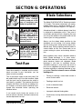
6. OPERATIONS..........................................................................................................27
TEST RUN..........................................................................................................27
BLADE SELECTIONS........................................................................................27
CUTTING CURVES............................................................................................28
RESAWING ........................................................................................................28
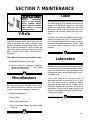
7. MAINTENANCE ......................................................................................................29
V-BELTS ............................................................................................................29
MISCELLANEOUS ............................................................................................29
TABLE ................................................................................................................29
LUBRICATION ..................................................................................................29
8. CLOSURE................................................................................................................30
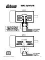
WIRE DIAGRAM ................................................................................................31
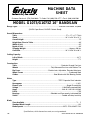
MACHINE DATA ................................................................................................32
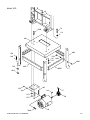
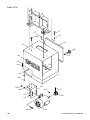
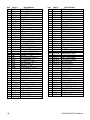
PARTS BREAKDOWN AND PARTS LISTS ................................................33-40
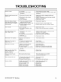
TROUBLESHOOTING GUIDE ..........................................................................41
WARRANTY AND RETURNS............................................................................42

-2- G1073/G1073Z 16" Bandsaw
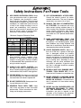
Safety Instructions For Power Tools
SECTION 1: SAFETY
5. KEEP CHILDREN AND VISITORS
AWAY. All children and visitors should be
kept a safe distance from work area.
6. MAKE WORKSHOP CHILD PROOF with
padlocks, master switches, or by removing
starter keys.
7. DO NOT FORCE TOOL. It will do the job
better and safer at the rate for which it was
designed.
8. USE RIGHT TOOL. Do not force tool or
attachment to do a job for which it was not
designed.
1. KEEP GUARDS IN PLACE and in working
order.
2. REMOVE ADJUSTING KEYS AND
WRENCHES. Form habit of checking to
see that keys and adjusting wrenches are
removed from tool before turning on.
3. KEEP WORK AREA CLEAN. Cluttered
areas and benches invite accidents.
4. DO NOT USE IN DANGEROUS ENVI-
RONMENT. Do not use power tools in
damp or wet locations, or where any flam-
mable or noxious fumes may exist. Keep
work area well lighted.
For Your Own Safety Read Instruction
Manual Before Operating This Equipment
Indicates an imminently hazardous situation which, if not avoided,
WILL result in death or serious injury.
Indicates a potentially hazardous situation which, if not avoided,
COULD result in death or serious injury.
Indicates a potentially hazardous situation which, if not avoided,
MAY result in minor or moderate injury. It may also be used to alert
against unsafe practices.
This symbol is used to alert the user to useful information about
proper operation of the equipment.
The purpose of safety symbols is to attract your attention to possible hazardous conditions. This
manual uses a series of symbols and signal words which are intended to convey the level of
importance of the safety messages. The progression of symbols is described below. Remember
that safety messages by themselves do not eliminate danger and are not a substitute for proper
accident prevention measures.
NOTICE

G1073/G1073Z 16'' Bandsaw -3-
9. USE PROPER EXTENSION CORD. Make
sure your extension cord is in good condi-
tion. Conductor size should be in accor-
dance with the chart below. The amperage
rating should be listed on the motor or tool
nameplate. An undersized cord will cause
a drop in line voltage resulting in loss of
power and overheating. Your extension
cord must also contain a ground wire and
plug pin. Always repair or replace exten-
sion cords if they become damaged.
Minimum Gauge for Extension Cords
10. WEAR PROPER APPAREL. Do not wear
loose clothing, gloves, neckties, rings,
bracelets, or other jewelry which may get
caught in moving parts. Non-slip footwear
is recommended. Wear protective hair cov-
ering to contain long hair.
11. ALWAYS USE SAFETY GLASSES. Also
use face or dust mask if cutting operation is
dusty. Everyday eyeglasses only have impact
resistant lenses, they are NOT safety glasses.
12. SECURE WORK. Use clamps or a vise to hold
work when practical. It is safer than using your
hand and frees both hands to operate tool.
13. DO NOT OVERREACH. Keep proper foot-
ing and balance at all times.
14. MAINTAIN TOOLS WITH CARE. Keep
tools sharp and clean for best and safest
performance. Follow instructions for lubri-
cating and changing accessories.
Safety Instructions For Power Tools
15. USE RECOMMENDED ACCESSORIES.
Consult the owner’s manual for recom-
mended accessories. The use of improper
accessories may cause risk of injury.
16. REDUCE THE RISK OF UNINTENTION-
AL STARTING. On machines with mag-
netic contact starting switches there is a
risk of starting if the machine is bumped or
jarred. Always disconnect from power
source before adjusting or servicing. Make
sure switch is in OFF position before recon-
necting.
17. MANY WOODWORKING TOOLS CAN
“KICKBACK” THE WORKPIECE toward
the operator if not handled properly. Know
what conditions can create “kickback” and
know how to avoid them. Read the manual
accompanying the machine thoroughly.
18. CHECK DAMAGED PARTS. Before fur-
ther use of the tool, a guard or other part
that is damaged should be carefully
checked to determine that it will operate
properly and perform its intended function.
Check for alignment of moving parts, bind-
ing of moving parts, breakage of parts,
mounting, and any other conditions that
may affect its operation. A guard or other
part that is damaged should be properly
repaired or replaced.
19. NEVER LEAVE TOOL RUNNING UNAT-
TENDED. TURN POWER OFF. Do not
leave tool until it comes to a complete stop.
20. NEVER OPERATE A MACHINE WHEN
TIRED, OR UNDER THE INFLUENCE OF
DRUGS OR ALCOHOL. Full mental alert-
ness is required at all times when running
a machine.
21. NEVER ALLOW UNSUPERVISED OR
UNTRAINED PERSONNEL TO OPER-
ATE THE MACHINE. Make sure any
instructions you give in regards to the
operation of the machine are approved,
correct, safe, and clearly understood.
LENGTH
AMP RATING 25ft 50ft 100ft
0-6 18 16 16
7-10 18 16 14
11-12 16 16 14
13-16 14 12 12
17-20 12 12 10
21-30 10 10 No

-4- G1073/G1073Z 16" Bandsaw
Additional Safety Instructions For Bandsaws
7. ALWAYS FEED STOCK EVENLY AND
SMOOTHLY. Do not force or twist blade
while cutting, especially when sawing
small radii.
8. THIS MACHINE IS NOT DESIGNED TO
CUT METAL or other material except
wood.
9. BLADE SHOULD BE RUNNING AT FULL
SPEED before beginning a cut.
10. DO NOT MANUALLY STOP OR SLOW
BLADE after turning the saw off. Allow it to
come to a complete stop before you leave
it unattended.
11. ALL INSPECTIONS, ADJUSTMENTS,
AND MAINTENANCE ARE TO BE DONE
WITH THE POWER OFF and the plug
pulled from the outlet. Wait for all moving
parts to come to a complete stop.
12. HABITS – GOOD AND BAD – ARE HARD
TO BREAK. Develop good habits in your
shop and safety will become second-
nature to you.
13. IF AT ANY TIME YOU ARE EXPERIENC-
ING DIFFICULTIES PERFORMING THE
INTENDED OPERATION, STOP USING
THE BANDSAW! Then contact our service
department or ask a qualified expert how
the operation should be performed.
1. DO NOT OPERATE WITH DULL OR
BADLY WORN BLADES. Dull blades
require more effort to use and are difficult
to control. Inspect blades before each use.
2. NEVER POSITION FINGERS OR
THUMBS IN LINE WITH THE CUT.
Serious personal injury could occur.
3. DO NOT OPERATE THIS BANDSAW
WITHOUT WHEEL, PULLEY, AND
BLADE GUARDS IN PLACE.
4. WHEN REPLACING BLADES, make sure
teeth face down toward the table. The
force of the cut is always down. Make sure
the blade is properly tensioned.
5. CUTS SHOULD ALWAYS BE FULLY
SUPPORTED by the table or some type of
support fixture. Always support round stock
in a V-block.
6. DO NOT BACK WORKPIECE AWAY from
the blade while the saw is running. Plan
your cuts so you always cut out of the
wood. If you need to back the work out,
turn the bandsaw off and wait for the blade
to come to a complete stop. Do not twist or
put excessive stress on the blade while
backing work away.
No list of safety guidelines can be com-
plete. Every shop environment is different.
Always consider safety first, as it applies
to your individual working conditions. Use
this and other machinery with caution and
respect. Failure to do so could result in
serious personal injury, damage to equip-
ment or poor work results.
Like all power tools, there is danger associ-
ated with bandsaws. Accidents are frequent-
ly caused by lack of familiarity or failure to
pay attention. Use this tool with respect and
caution to lessen the possibility of operator
injury. If normal safety precautions are over-
looked or ignored, serious personal injury
may occur.

G1073/G1073Z 16'' Bandsaw -5-
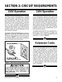
220V Operation
The Model G1073/G1073Z Bandsaw is supplied
with a dual-voltage 110V/220V motor, prewired
for 220V operation. Under normal use, the motor
draws approximately 12 amps at 220V. We rec-
ommend a 15 amp circuit breaker or slow-blow
fuse for 220V. This should be satisfactory for nor-
mal use, while providing enough protection
against damage caused by an overloaded circuit.
If frequent circuit failures occur when using the
bandsaw, contact our service department or your
local electrical contractor.
The Model G1073/G1073Z Bandsaw is not sup-
plied with a power plug. We recommend using a
NEMA-style L6-15 plug and outlet similar to the
one shown in Figure 1. You may also “hard-wire”
the bandsaw directly to your panel, provided you
place a disconnect near the machine.
110V Operation
If 110 volt operation is desired, refer to the wiring
diagram in the back of this manual. Under normal
use, the motor draws approximately 24 amps at
110V. We recommend using a circuit breaker and
wires rated for 30 amps. This should be satisfac-
tory for normal use, while providing enough pro-
tection against damage caused by power surges.
If frequent circuit failures occur when using the
bandsaw, contact our service department or your
local electrical contractor.
The Model G1073/G1073Z is not supplied with a
power plug. It will be necessary to supply your
own standard 110V, 30 Amp grounded plug and
receptacle as shown in Figure 2.
SECTION 2: CIRCUIT REQUIREMENTS
Figure 1. Typical 220V 3-prong plug and outlet.
We do not recommend the use of extension
cords on 220V equipment. It is much better to
arrange the placement of your equipment and the
installed wiring to eliminate the need for exten-
sion cords. Should it be necessary to use an
extension, make sure the cord is rated Hard
Service (Grade S) or better. Refer to the chart on
page 3 to determine the minimum gauge for the
extension cord. The extension cord must also
contain a ground wire and plug pin. Always repair
or replace extension cords when they become
worn or damaged.
Extension Cords
Be sure that your particular electrical config-
uration complies with local and state codes.
The best way to ensure compliance is to
check with your local municipality or
licensed electrician.

-6- G1073/G1073Z 16" Bandsaw
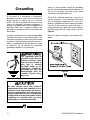
Figure 2.
Under no circumstances should the grounding
pin from any three-pronged plug be removed. If it
will not fit the outlet, have the proper outlet
installed by a qualified electrician.
Check with a qualified electrician or one of our
service personnel if the grounding instructions
are not completely understood, or if you are in
doubt as to whether the tool is properly grounded.
Use only 3-wire extension cords that have 3-
prong grounding type plugs and 3-hole recepta-
cles that accept the tool’s plug, similar to that in
Figure 2.
Repair or replace damaged or worn cords imme-
diately.
Grounding
In the event of a malfunction or breakdown,
grounding provides a path of least resistance for
electric current to reduce the risk of electric
shock. This tool is equipped with an electric cord
having an equipment grounding conductor. A
plug with a grounding pin must be plugged into a
matching outlet that is properly installed and
grounded in accordance with all local codes and
ordinances.
Improper connections of the electrical-grounding
conductor can result in risk of electric shock. The
conductor with green or green and yellow striped
insulation is the electrical grounding conductor. If
repair or replacement of the electric cord or plug
is necessary, do not connect the equipment
grounding conductor to a live terminal.
We have covered some basic electrical
requirements for the safe operation of your
bandsaw. These requirements are not nec-
essarily comprehensive. You must be sure
that your particular electrical configuration
complies with local and state codes. Ensure
compliance by checking with your local
municipality or a licensed electrician.
This equipment must be
grounded. Verify that any
existing electrical outlet
and circuit you intend to
plug into is actually
grounded. Under no cir-
cumstances should the
grounding pin from any
three-pronged plug be
removed. Serious injury
may occur.

G1073/G1073Z 16'' Bandsaw -7-
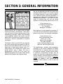
Grizzly Industrial, Inc. is proud to offer the Model
G1073 and G1073Z 16" Bandsaws. These band-
saws are a part of Grizzly’s growing family of fine
woodworking machinery. When used according
to the guidelines stated in this manual, you can
expect years of trouble-free, enjoyable operation,
and proof of Grizzly’s commitment to customer
satisfaction.
The Models G1073 and G1073Z are essentially
the same machine with the exception of the dif-
ferent style stands. Both feature a cast iron, one-
piece body, 3 speed pulley system, and a 7
3
⁄4"
cutting height. Also included are a fence, miter
gauge, guards, and
1
⁄2" blade. The saw is
equipped with a 1725 R.P.M., 2 H.P. motor. The
Model G1073 comes with an open stand, and the
Model G1073Z comes with a cabinet stand.
SECTION 3: GENERAL INFORMATION
We are also pleased to provide this manual with
the Model G1073/G1073Z. It was written to guide
you through assembly, review safety considera-
tions, and cover general operating procedures. It
represents our latest effort to produce the best
documentation possible. If you have any com-
ments or criticisms that you feel we should
address in our next printing, please write to us at:
Grizzly Industrial, Inc.
C
⁄O Technical Documentation
P.O. Box 2069
Bellingham, WA 98227
Most important, we stand behind our machines. If
you have any service questions or parts requests,
please call or write us at the location listed below.
Grizzly Industrial, Inc.
1203 Lycoming Mall Circle
Muncy, PA 17756
Phone: (570) 546-9663
Fax: (800) 438-5901
E-Mail: [email protected]
Web Site: http://www.grizzly.com
The specifications, drawings, and photographs
illustrated in this manual represent the Model
G1073/G1073Z as supplied when the manual
was prepared. However, owing to Grizzly’s policy
of continuous improvement, changes may be
made at any time with no obligation on the part of
Grizzly. However, we always keep current Grizzly
manuals available on our website at www.griz
-
zly.com. Any updates in your machine will be
reflected in these manuals as soon as they are
complete.
Read the manual before
assembly and operation.
Become familiar with
the machine and its
operation before begin-
ning any work. Serious
personal injury may
result if safety or opera-
tional information is not
understood or followed.

-8- G1073/G1073Z 16" Bandsaw
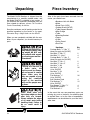
Piece Inventory
After all the parts have been removed from the
carton, you should have:
• Bandsaw Unit with Blade
• Motor
• Stand Parts (1073)
• Cabinet Stand (1073Z)
• Table Support Bracket
• Miter Gauge
• Table
• Mounting Bracket
• Fence
• V-Belt
• Pulley Guard
• Dust Port
Hardware Qty
Carriage Bolts
5
⁄16"-18 x
5
⁄8" 24
(does not apply for G1073Z)
Hex Bolts
1
⁄4"-20 x
3
⁄4"2
Hex Bolts
5
⁄16"-18 x 1" 4
Carriage Bolts
5
⁄16"-18 x 1" 4
(does not apply for G1073Z)
Hex Bolts
3
⁄8"-16 x 1" 2
Hex Bolts
3
⁄8"-16 x 2" 4
Hex Nuts
1
⁄4
"-20 2
Hex Nuts
5
⁄16"-18 32
(4 for G1073Z)
Hex Nuts
3
⁄8
"-16 6
(4 for G1073Z)
Flat Washers
5
⁄16"32
(4 for G1073Z)
Anti Vibration Pads 4
Flat Washers
3
⁄8"12
(8 for G1073Z)
Cap Screws
1
⁄4"-20 x 1
1
⁄4"4
Fence Rail Spacers 4
Flat Washers
1
⁄4"4
In the event that any non-proprietary parts are
missing (e.g. nuts or washers), we would be glad
to replace them, or for the sake of expediency,
replacements can be obtained at your local hard-
ware store.
Unpacking
The Model G1073 Bandsaw is shipped from the
manufacturer in a carefully packed carton, and
the Model G1073Z is shipped in two cartons. If
you discover the machine is damaged after you
have signed for delivery, please call Customer
Service immediately for advice.
Save the containers and all packing materials for
possible inspection by the carrier or its agent.
Otherwise filing a freight claim can be difficult.
When you are completely satisfied with the con-
dition of your shipment, you should inventory its
parts.
The Model G1073/G1073Z is a
heavy machine (456 lbs. ship-
ping weight). DO NOT over-
exert yourself while unpack-
ing or moving your machine –
get assistance.
If moving this machine up
or down stairs, the
machine must be disman-
tled and moved in smaller
pieces. Make sure the
stairs are capable of sup-
porting the combined
weight of the machine
parts and the people mov-
ing them.
Some metal parts may
have sharp edges on them
after they are formed.
Please examine the edges
of all metal parts before
handling them. Failure to
do so could result in
injury.

G1073/G1073Z 16'' Bandsaw -9-
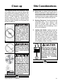
Clean up Site Considerations
1. Floor Load: Your Model G1073/G1073Z 16''
Bandsaw represents a large weight load in a
small footprint. Most commercial floors are
suitable for the Model G1073/G1073Z. Some
residential floors may require additional build
up to support both machine and operator.
2. Working Clearances: Consider existing and
anticipated needs, size of material to be
processed through each machine, and
space for auxiliary stands, work tables or
other machinery when establishing a loca-
tion for your bandsaw.
3. Lighting and Outlets: Lighting should be
bright enough to eliminate shadow and pre-
vent eye strain. Electrical circuits should be
dedicated or large enough to handle amper-
age requirements. Outlets should be located
near each machine so power or extension
cords are clear of high-traffic areas. Observe
local electrical codes for proper installation
of new lighting, outlets, or circuits.
The unpainted surfaces are coated with a waxy
oil to protect them from corrosion during ship-
ment. Remove this protective coating with a sol-
vent cleaner or citrus-based degreaser such as
Grizzly’s G7895 Degreaser. Avoid chlorine-
based solvents as they may damage painted
surfaces should they come in contact. Always
follow the usage instructions on the product you
choose for clean up.
Do not use gasoline or
other petroleum-based
solvents to clean with.
They have a low flash
point which makes them
extremely flammable. A
risk of explosion and
burning exists if these
products are used.
Serious personal injury
may occur.
Make your shop “child safe.”
Ensure that your workplace
is inaccessible to children
by closing and locking all
entrances when you are
away. Never allow visitors in
your shop when assembling,
adjusting, or operating
equipment.
Do not smoke while using
solvents. A risk of explo-
sion or fire exists and may
result in serious personal
injury.
Many of the solvents
commonly used to clean
machinery can be toxic
when inhaled or ingest-
ed. Always work in well-
ventilated areas far from
potential ignition sources
when dealing with sol-
vents. Use care when dis-
posing of waste rags and
towels to be sure they do
not create fire or environ-
mental hazards.

-10- G1073/G1073Z 16" Bandsaw
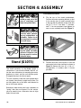
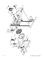
SECTION 4: ASSEMBLY
Figure 3. Attaching motor mount bracket.
Figure 4. Motor attached to motor mount bracket.
Stand (G1073)
The stand assembly on the Model G1073 is
shown here. If you have the Model G1073Z, fol-
low the same instructions for mounting the motor,
bandsaw to stand, and the anti-vibration pads.
Disregard the steps that do not apply.
To ease assembly, build the stand upside down
on a bench, then place it upright on the floor. Do
not fully tighten any of the bolts until directed to
do so in the next section.
Sometimes sheet metal parts have a tendency to
''spring'' after they are formed. For this reason,
you may need to use a little extra force to align
holes to insert bolts.
2. Position the motor so the pulley is over the
rectangular hole in the stand top as shown in
Figure 4. Secure with four (4)
5
⁄16"-18 x 1"
carriage bolts,
5
⁄16" washers, and
5
⁄16"-18 nuts
provided.
To assemble the stand:
1. Flip the top of the stand upside-down.
Position the motor mounting bracket so that
it sits over the four (4) evenly spaced holes
in the top. Bolt the bracket to the stand with
two (2)
3
⁄8"-16 x 1" hex bolts,
3
⁄8" washers,
and
3
⁄8"-16 nuts provided. Hand tighten for
now so your assembly looks like Figure 3.
Keep loose clothing
rolled up and out of the
way of machinery and
keep hair pulled back.
Wear safety glasses dur-
ing the entire assembly
process. Failure to com-
ply may result in serious
personal injury.
Disconnect power to the
machine when perform-
ing any maintenance or
assembly. Failure to do
this may result in serious
personal injury.

G1073/G1073Z 16'' Bandsaw -11-
Figure 5. Legs and braces attached to top.
3. Attach the four (4) legs to the inside of the
stand top and the four horizontal braces to
the inside of the legs as shown in Figure 5.
Use the
5
⁄16"-18 x
5
⁄8" carriage bolts,
5
⁄16"-18
nuts, and
5
⁄16" washers provided. The two
shorter braces are slightly wider than the
longer braces. When attaching the braces to
the legs, the longer braces rest inside the
two flanges of the shorter braces. The
square holes in the legs are angled to
accommodate the angle of the legs.
4. Attach the four (4) rubber feet to the legs.
Use four (4)
5
⁄16"-18 x 1" hex head bolts, four
(4)
5
⁄16" flat washers and four (4)
5
⁄16"-18 nuts
provided. The bolts should go through the
pad first and then through the feet. Tighten
carefully so you do not deform the rubber
feet.
5. Slide the motor pulley onto the motor shaft
and tighten the setscrew down. The small
end of the pulley should be near the motor.
6. Flip the stand/motor assembly rightside-up
on the floor, but do not tighten the stand
hardware at this time.
Rubber Feet
Motor Pulley
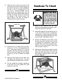
Figure 6.
Bandsaw Mounting Holes
Bandsaw To Stand
1. Safely lift the bandsaw onto the stand.
Ensure that the bandsaw step pulley is posi-
tioned over the hole in the stand.
2. Attach the bandsaw to the stand with four (4)
3
⁄8"-16 x 2" hex bolts, four (4)
3
⁄8"-16 hex nuts,
and eight (8)
3
⁄8" washers provided. The bolts
on the left side should go through the motor
mount bracket. Hand tighten for now.
3. Position the bandsaw on the stand so that
the legs are evenly balanced and the stand
is symmetrical in appearance, rather than
lopsided. When the stand is positioned cor-
rectly on all four sides, tighten all the stand
nuts to secure it in place.
4. Working from the bottom up, tighten all stand
bolts, motor mount bracket to the stand top
(leave the motor bolts loose for now), and
the bandsaw mounting bolts at the holes
shown in Figure 6.
The bandsaw (without stand
and motor) weighs approxi-
mately 325 lbs. Use a lifting
device or get help from peo-
ple who can safely lift that
much weight. Serious per-
sonal injury may occur if
this warning is ignored.

-12- G1073/G1073Z 16" Bandsaw
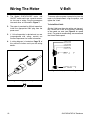
Figure 8. Pulley speed chart diagram.
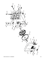
V-Belt
To ensure optimum power transmission from the
motor to the band wheels, align the pulleys, and
tighten the V-belt.
To install the V-belt:
Slip the V-belt over the motor pulley and step pul-
ley. Position the V-belt on the pulleys according
to the speed you want (see Figure 8 for speed
chart). For general woodworking, we recommend
the fastest blade speed.
Figure 7. Plugging cords together.
Wiring The Motor
1. The Model G1073/G1073Z motor and
ON/OFF switch each have a special connec-
tor for ease of wiring. Plug the connectors
into each other as illustrated in Figure 7.
2. The motor is prewired for 220 volt operation.
Install the appropriate 220V plug onto the
power cord.
3. If 110 volt operation is desired and you are
inexperienced with wiring, contact our
Service Department for further information.
4. A wiring diagram is located on Page 31 of
this manual to further assist you with wiring
details.

G1073/G1073Z 16'' Bandsaw -13-
Figure 10. Aligning V-belt pulleys.
Pulley alignment and belt tension should now
be adjusted simultaneously.
1. Situate the motor so the V-grooves on the
motor pulley approximately line up with the
V-grooves on the three-step pulley. You may
need to loosen the motor mount bracket
bolts shown in Figure 9A to position the
motor properly. Tighten the mount bracket to
the stand before moving on to the next step.
Leave the motor mount bolts loose.
Figure 9B. Pulley deflection w/moderate pressure.
Figure 9A. Motor mount bolt locations.
If the pulleys will not align by moving the
motor only, loosen the bandsaw mounting
bolts and position the bandsaw so the step
pulley aligns with the motor pulley. Leave the
motor mount bolts loose.
2. Slide the motor up or down to achieve prop-
er V-belt tension. You should be able to
deflect the V-belt about
3
⁄4" at its midpoint
(see Figure 9B) using moderate finger pres-
sure. Be careful not to change the lateral
position of the motor and move the pulleys
out of alignment. Tighten the motor mount
bolts.
Plumb bob
Motor Mount
Bolts
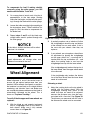
3. Check the pulley alignment with a plumb bob
or straightedge. If you are using a plumb
bob, the string must touch the outside
flanges of each pulley evenly as shown in
Figure 10, and the machine must be level.
4. Check V-belt tension. Repeat steps 1-4 until
both tension and pulley alignment are cor-
rect.

-14- G1073/G1073Z 16" Bandsaw
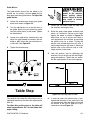
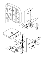
Figure 11. Trunnions removed from bandsaw.
Figure 12. Under table controls.
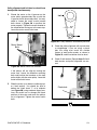
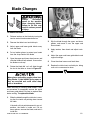
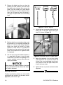
7. Place the table insert in the table top and
slide the table pin so it fits snugly in the hole
on the right side of the table. DO NOT use
excessive force.
2. Place the trunnion support on the body cast-
ing over the mounting holes, and secure it
with the three bolts you just removed, mak-
ing sure the support is placed so that the
blade is centered between the guide-block
brackets.
3. Release tension and remove blade. Refer to
“Blade Changes” instructions if you need
help. Position the table so that the miter slot
will be to the right of the blade as you face
the front of the bandsaw.
4. Orient the trunnion bolts under the table so
they hang vertically.
5. Set the table trunnions onto the support.
Make sure the trunnion bolts drop through
the trunnion support slots.
6. Secure the table to the trunnion supports by
tightening the two star knobs onto the trun-
nion bolts shown in Figure 12.
Working Table
The table secures to the trunnion support which
mounts to the body casting. The trunnions are
premounted to the table.
To mount the table and trunnion support:
1. Remove the three table bracket mounting
bolts from the bandsaw body. Figure 11
shows them removed.
Star Knobs
Trunnion
Table Pin
Trunnion
Trunnion
Support
Trunnion Support Mounting Holes
NOTICE
The tapered table pin must be in position
when operating the bandsaw.

G1073/G1073Z 16'' Bandsaw -15-
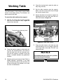
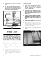
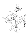
Figure 13. Fence rails properly secured to table.
Figure 14. Fence mounted on rails.
2. Screw the fence locking handle into its posi-
tion on the cam on the fence headstock.
Move it to the loose (up) position.
3. Slide the fence onto the fence rails as shown
in Figure 14.
Fence
The mounting holes in the rails are not centered
on the length of the rails. This way, you can
mount the rails so that maximum fence travel will
be greater on one side or the other.
To mount the rails:
1. Secure the fence rails to the table with the
four (4)
1
⁄4"-20 x 1
1
⁄4" cap screws and spacers
provided (Figure 13).
Rail Spacers
There are two ways to remove the fence:
1. Remove the blade so the fence slides off
the rails.
2. Dismount the rails by removing the cap
screws.
NOTICE
When the fence is to the left of the blade,
the fence must be positioned near the cen-
ter of the table in order to open the lower
wheel cover.

-16- G1073/G1073Z 16" Bandsaw
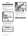
Figure 15. Belt guard and dust port mounted
correctly on bandsaw.
Guard
Place the belt guard over the step pulley and
secure it, as shown in Figure 15, to the stand
using the
1
⁄4"-20 x
1
⁄2" hex head bolts, washers,
and nuts provided. Fasten the guard to the band-
saw by inserting the threaded rod through to the
body casting and tightening the knob.
Dust Port
The Model G1073 comes standard with a 2
1
⁄2"
dust port for dust collection. It mounts to the lower
rear casting body. This port can be connected
directly to a 2
1
⁄2" Shop•Vac
®
hose or adapted to fit
a standard 4" dust collector hose by using the
Grizzly Model G3119 adapter between a 2
1
⁄2" and
4" hose.
To mount the dust port:
1. Remove the four dust port mounting screws
from the bandsaw body and position the dust
port as shown in Figure 15.
2. Replace the screws and secure the dust port
to the bandsaw body.
Dust Port
Belt Guard

G1073/G1073Z 16'' Bandsaw -17-
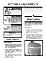
Blade Tension
Blade Tracking
SECTION 5: ADJUSTMENTS
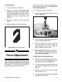
To adjust the tension:
1. Loosen the upper and lower guide blocks
and lower the upper guide block down to the
table. With moderate tension already on the
blade, turn the bandsaw ON.
2. Release the tension one quarter of a turn at
a time. Do this very slowly. When you see
the bandsaw blade start to flutter, stop
decreasing the tension.
3. Now, slowly increase the tension until the
blade stops fluttering. Tighten the tension
one quarter of a turn.
There are two ways to track a bandsaw blade:
Center Tracking and Coplanar Tracking.
Center Tracking is the fastest and easiest, but not
the most precise.
Center Tracking:
1. Disconnect the bandsaw from the power
source and adjust the upper and lower guide
assemblies away from the blade. Refer to
Page 18 for adjustment details.
2. Loosen the lock collar on the tracking control
knob shown in Figure 17. Turn the tracking
control knob clockwise/counterclockwise
while turning the upper wheel by hand until
the blade stays centered on the rubber tire.
Keep loose clothing
rolled up and out of the
way of machinery and
keep hair pulled back.
Wear safety glasses dur-
ing the entire adjust-
ments process. Failure
to comply may result in
serious personal injury.
Disconnect power to the
machine when perform-
ing any maintenance or
assembly. Failure to do
this may result in serious
personal injury.
If the tension seems correct, turn the bandsaw
OFF and make the other adjustments, and test
run. If the blade does not cut properly, the tension
may be incorrect. Readjust the tension. New
blades often stretch with use. However, it helps to
always remove the tension from the blade when
not in use.
Figure 17. Tracking and tension controls.
Tracking Knob
Lock Collar
Tension Knob
NOTICE
Read through the entire manual before
starting the table saw.

-18- G1073/G1073Z 16" Bandsaw
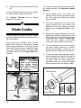
Blade Guides
You must check the upper and lower support
bearings and guide blocks each time before start-
ing your bandsaw.
Always adjust the assemblies away from the
blade before installing a new blade or making
blade tracking adjustments. After blade tension
and tracking are set correctly, readjust the upper
and lower support bearings and guide block
assemblies into position. See Figure 18A control
locations.
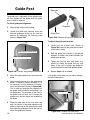
Figure 18A. Upper guide assembly.
Figure 18B. Eccentric blade support.
Adjustment
Knobs
The support bearings back-up the blade during
the sawing operation. To adjust the support
bearings:
1. Loosen guide blocks and loosen the
setscrew that holds the guide block assem-
bly to the guide post. Remove the guide
block assembly.
2. Loosen the thumbscrew that secures the
support bearing shaft and unscrew the
adjustment knob that controls the support
bearing shaft. See Figures 18A/B for loca-
tions.
3. Remove the support bearing shaft from the
guide block assembly. Rotate the the shaft
so the blade will ride off-center against the
support bearing as shown in Figure 18B.
Install the shaft, tighten the mounting
setscrew and replace the adjustment cap.
4. Turn the adjustment cap so that the upper
and lower support bearings are approxi-
mately .016" (thickness of a dollar bill x 4)
behind the blade. Tighten the thumbscrews.
5. To adjust the lower support bearing, remove
the lower guide block assembly by taking out
the two setscrews that mount it to the band-
saw body. Make the same adjustments
described in steps 2-4 and mount the guide
block assembly back to the bandsaw body.
Support Bearing
Support Bearing
Shaft
Guide Block
Eccentric Shaft
Support Bearing
Always disconnect
power to the machine
when making adjust-
ments. Failure to do this
may result in serious
personal injury.
3. Tighten the lock collar and check the track-
ing.
For the best performance from your saw, regular-
ly maintain proper tracking of the blade.
For Coplanar Tracking, see the “Wheel
Alignment” instructions.
Page is loading ...
Page is loading ...
Page is loading ...
Page is loading ...
Page is loading ...
Page is loading ...
Page is loading ...
Page is loading ...
Page is loading ...
Page is loading ...
Page is loading ...
Page is loading ...
Page is loading ...
Page is loading ...
Page is loading ...
Page is loading ...
Page is loading ...
Page is loading ...
Page is loading ...
Page is loading ...
Page is loading ...
Page is loading ...
Page is loading ...
Page is loading ...
Page is loading ...
Page is loading ...
Page is loading ...
Page is loading ...
-
 1
1
-
 2
2
-
 3
3
-
 4
4
-
 5
5
-
 6
6
-
 7
7
-
 8
8
-
 9
9
-
 10
10
-
 11
11
-
 12
12
-
 13
13
-
 14
14
-
 15
15
-
 16
16
-
 17
17
-
 18
18
-
 19
19
-
 20
20
-
 21
21
-
 22
22
-
 23
23
-
 24
24
-
 25
25
-
 26
26
-
 27
27
-
 28
28
-
 29
29
-
 30
30
-
 31
31
-
 32
32
-
 33
33
-
 34
34
-
 35
35
-
 36
36
-
 37
37
-
 38
38
-
 39
39
-
 40
40
-
 41
41
-
 42
42
-
 43
43
-
 44
44
-
 45
45
-
 46
46
-
 47
47
-
 48
48


Grizzly G1073 Owner's manual
- Category
- Power tools
- Type
- Owner's manual
- This manual is also suitable for
Ask a question and I''ll find the answer in the document
Finding information in a document is now easier with AI
Related papers


Other documents
-
General 90-050 Setup & Operation Manual
-
Rikon Power Tools 10-326 User manual
-
General International 90-140 M1 User guide
-
-
-
Panasonic DS-52 Installation guide
-
-
Rikon Power Tools 10-324 User manual
-
-