JVC Projection Television DLA-HD2KE User manual

Category
Data projectors
Type
User manual
INSTRUCTIONS
DLA-HD2KU/DLA-HD2KE
®
®
HOME THEATER PROJECTOR
DLA-HD2KU
LCT1719-001A
For Customer Use:
Serial No.
Model No.
Enter below the Serial No. which is located
on the side panel of the cabinet. Retain
this information for future reference.
ON
ENTER
OFF
FOCUS
TEST
MENU EXIT
PRESET
HIDE
LIGHT
OPERATE
2
About burning-in of the D-ILA device
Do not allow the same still picture to be projected for a long
time or an abnormally bright video picture to be projected.
Do not project video images with high-intensity or high con-
trast
on a screen. The video image could be burnt into the D-ILA
device.
Use special care when projecting video games or computer
program images. There is no problem with ordinary video-cas-
sette playback images.
About the installation place
Do not install the projector in a place that cannot support its
weight securely.
If the installation place is not sturdy enough, the projector could
fall or overturn, possibly causing personal injury.
IMPORTANT SAFEGUARDS
Electrical energy can perform many useful functions. This unit
has been engineered and manufactured to assure your per-
sonal safety. But IMPROPER USE CAN RESULT IN POTEN-
TIAL ELECTRICAL SHOCK OR FIRE HAZARD. In order not
to defeat the safeguards incorporated into this product, ob-
serve the following basic rules for its installation, use and ser-
vice. Please read these Important Safeguards carefully be-
fore use.
All the safety and operating instructions should be read be-
fore the product is operated.
The safety and operating instructions should be retained
for future reference.
All warnings on the product and in the operating instruc-
tions should be adhered to.
All operating instructions should be followed.
Place the projector near a wall outlet where the plug can be
easily unplugged.
Unplug this product from the wall outlet before cleaning. Do
not use liquid cleaners or aerosol cleaners. Use a damp
cloth for cleaning.
Do not use attachments not recommended by the product
manufacturer as they may be hazardous.
Do not use this product near water. Do not use immediately
after moving from a low temperature to high temperature,
as this causes condensation, which may result in fire, elec-
tric shock, or other hazards.
Do not place this product on an unstable cart, stand, or
table. The product may fall, causing serious injury to a child
or adult, and serious damage to the product. The product
should be mounted according to the manufacturer’s instruc-
tions, and should use a mount recom-
mended by the manufacturer.
When the product is used on a cart, care
should be taken to avoid quick stops, ex-
cessive force, and uneven surfaces which
may cause the product and cart to over-
turn, damaging equipment or causing pos-
sible injury to the operator.
IMPORTANT INFORMATION
WARNING:
TO PREVENT FIRE OR SHOCK HAZARDS, DO NOT
EXPOSE THIS APPLIANCE TO RAIN OR MOISTURE.
CAUTION:
To reduce the risk of electric shock, do not remove cover.
Refer servicing to qualified service personnel.
This projector is equipped with a 3-blade grounding type
plug to satisfy FCC rule. If you are unable to insert the plug
into the outlet, contact your electrician.
NOTICE (For USA)
Language for Manuals of Products using HID Lamps
(that contains mercury)
This product has a High Intensity Discharge (HID) lamp
that contains a small amount of mercury. It also contains
lead in some components.
Disposal of these materials may be regulated in your com-
munity due to environmental considerations. For disposal
or recycling information please contact your local authori-
ties, or the Electronics Industries Alliance: http://
www.eiae.org.
WARNING:
THIS APPARATUS MUST BE EARTHED.
MACHINE NOISE INFORMATION (Germany only)
Changes Machine Noise Information Ordinance 3.
GSGV, January 18, 1991: The sound pressure level at the
operator position is equal or less than 70 dB (A) according
to ISO 7779.
FCC INFORMATION (U.S.A. only)
CAUTION:
Changes or modification not approved by JVC could void
the user’s authority to operate the equipment.
NOTE:
This equipment has been tested and found to comply with
the limits for Class B digital devices, pursuant to Part 15 of
the FCC Rules. These limits are designed to provide rea-
sonable protection against harmful interference in a resi-
dential installation. This equipment generates, uses, and
can radiate radio frequency energy and, if not installed and
used in accordance with the instructions, may cause harm-
ful interference to radio communications. However, there
is no guarantee that interference will not occur in a par-
ticular installation. If this equipment does cause harmful
interference to radio or television reception, which can be
determined by turning the equipment off and on, the user
is encourage to try to correct the interference by one or
more of the following measures:
Reorient or relocate the receiving antenna.
Increase the separation between the equipment and re-
ceiver.
Connect the equipment into an outlet on a circuit differ-
ent from that to which the receiver is connected.
Consult the dealer or an experienced radio/TV techni-
cian for help.
PORTABLE CART WARNING
(symbol provided by RETAC)
S3126A
SAFETY PRECAUTIONS
3
Slots and openings in the cabinet are provided for ventila-
tion. These ensure reliable operation of the product and pro-
tect it from overheating. These openings must not be blocked
or covered. (The openings should never be blocked by plac-
ing the product on bed, sofa, rug, or similar surface. It should
not be placed in a built-in installation such as a bookcase or
rack unless proper ventilation is provided and the
manufacturer’s instructions have been adhered to.)
For proper ventilation, separate the product from other equip-
ment, which may prevent ventilation and keep a distance of
more than 11-7/8" (30 cm).
This product should be operated only with the type of power
source indicated on the label. If you are not sure of the type
of power supply to your home, consult your product dealer
or local power company.
This product is equipped with a three-wire plug. This plug
will fit only into a grounded power outlet. If you are unable to
insert the plug into the outlet, contact your electrician to
install the proper outlet. Do not defeat the safety purpose of
the grounded plug.
–Power-supply cords should be routed so that they are not
likely to be walked on or pinched by items placed upon or
against them. Pay particular attention to cords at doors,
plugs, receptacles, and the point where they exit from the
product.
–For added protection of this product during a lightning storm,
or when it is left unattended and unused for long periods of
time, unplug it from the wall outlet and disconnect the cable
system. This will prevent damage to the product due to light-
ning and power line surges.
Do not overload wall outlets, extension cords, or convenience
receptacles on other equipment as this can result in a risk
of fire or electric shock.
–Never push objects of any kind into this product through
openings as they may touch dangerous voltage points or
short out parts that could result in a fire or electric shock.
Never spill liquid of any kind on the product.
Do not attempt to service this product yourself as opening
or removing covers may expose you to dangerous voltages
and other hazards. Refer all service to qualified service per-
sonnel.
Unplug this product from the wall outlet and refer service to
qualified service personnel under the following conditions:
a) When the power supply cord or plug is damaged.
b) If liquid has been spilled, or objects have fallen on the
product.
c) If the product has been exposed to rain or water.
d) If the product does not operate normally by following the
operating instructions. Adjust only those controls that are
covered by the Operation Manual, as an improper ad-
justment of controls may result in damage and will often
require extensive work by a qualified technician to re-
store the product to normal operation.
e) If the product has been dropped or damaged in any way.
f) When the product exhibits a distinct change in perfor-
mance - this indicates a need for service.
When replacement parts are required, be sure the service
technician has used replacement parts specified by the
manufacturer or with same characteristics as the original
part. Unauthorized substitutions may result in fire, electric
shock, or other hazards.
Upon completion of any service or repairs to this product,
ask the service technician to perform safety checks to de-
termine that the product is in proper operating condition.
The product should be placed more than one foot away from
heat sources such as radiators, heat registers, stoves, and
other products (including amplifiers) that produce heat.
When connecting other products such as VCR’s, and per-
sonal computers, you should turn off the power of this prod-
uct for protection against electric shock.
Do not place combustibles behind the cooling fan. For ex-
ample, cloth, paper, matches, aerosol cans or gas lighters
that present special hazards when over heated.
Do not look into the projection lens while the illumination
lamp is turned on. Exposure of your eyes to the strong light
can result in impaired eyesight.
Do not look into the inside of this unit through vents (ventila-
tion holes), etc. Do not look at the illumination lamp directly
by opening the cabinet while the illumination lamp is turned
on. The illumination lamp also contains ultraviolet rays and
the light is so powerful that your eyesight can be impaired.
Do not drop, hit, or damage the light-source lamp (lamp unit)
in any way. It may cause the light-source lamp to break and
lead to injuries. Do not use a damaged light source lamp. If
the light-source lamp is broken, ask your dealer to repair it.
Fragments from a broken light-source lamp may cause inju-
ries.
The light-source lamp used in this projector is a high pres-
sure mercury lamp. Be careful when disposing of the light-
source lamp. If anything is unclear, please consult your
dealer.
Do not ceiling-mount the projector to a place which tends to
vibrate; otherwise, the attaching fixture of the projector could
be broken by the vibration, possibly causing it to fall or over-
turn, which could lead to personal injury.
Use only the accessory cord designed for this product to
prevent shock.
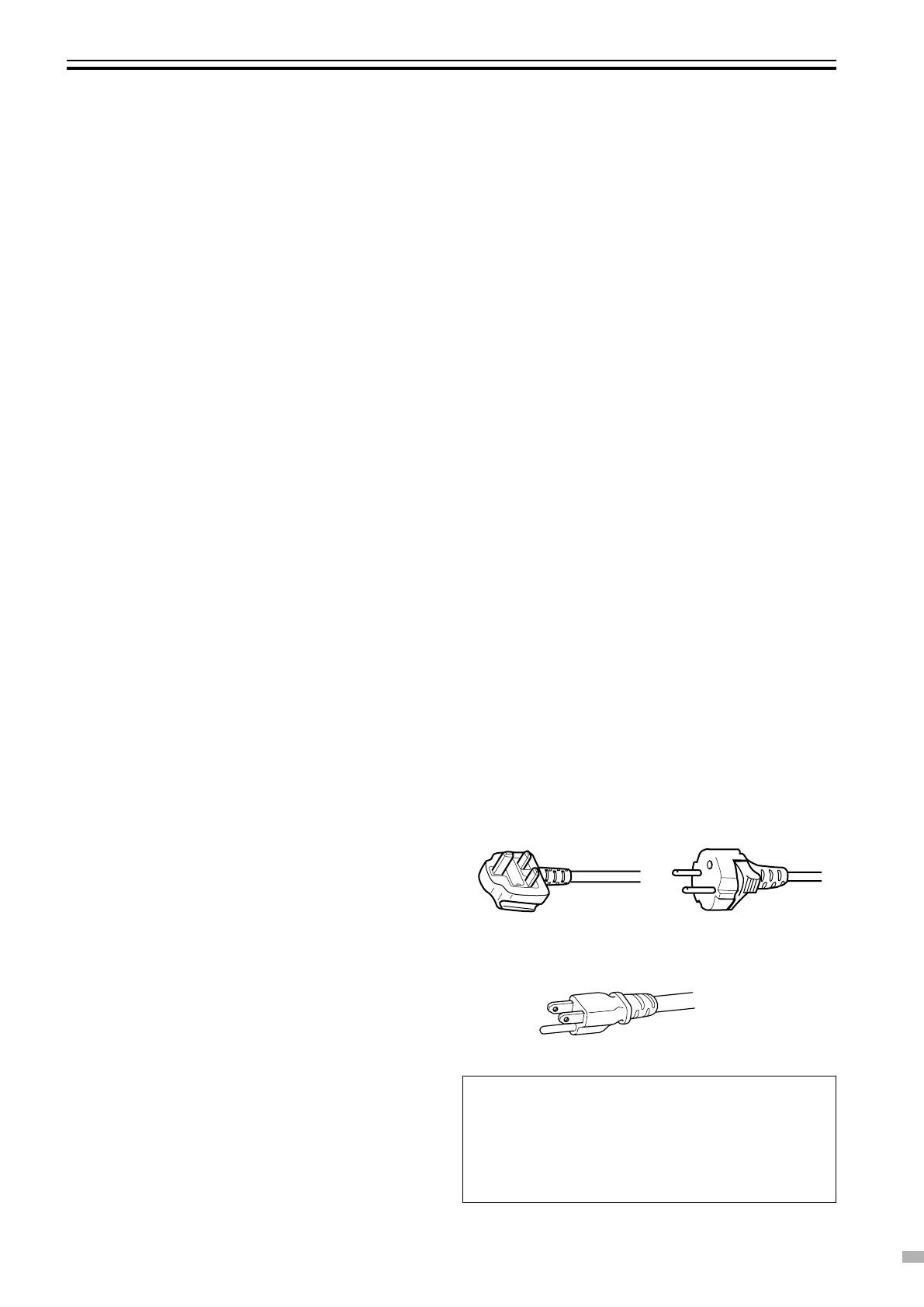
The power supply voltage rating of this product is AC 120 V,
AC 100 V– AC 240 V, the power cord attached conforms to
the following power supply voltage. Use only the power cord
designated by our dealer to ensure Safety and EMC.
When it is used by other power supply voltage, power cable
must be changed.
Ensure that the power cable used for the projector is the
correct type for the AC outlet in your country.
Consult your product dealer.
*DO NOT allow any unqualified person to install the unit.
Be sure to ask your dealer to install the unit (e.g. attaching
it to the ceiling) since special technical knowledge and skills
are required for installation.
If installation is performed by an unqualified person, it may
cause personal injury or electrical shock.
Power cord
For United
Kingdom
For European
continent countries
Power supply voltage: AC 120 V
Power cord
4
WARNING:
THIS APPARATUS MUST BE EARTHED. IMPORTANT:
The wires in the mains lead on this product are colored in
accordance with the following cord:
Green-and-yellow : Earth
Blue : Neutral
Brown : Live
As these colors may not correspond with the colored mak-
ing identifying the terminals in your plug, proceed as fol-
lows:
The wire which is colored green-and-yellow must be con-
nected to the terminal which is marked
with the letter E
or the safety earth or colored green or green-and-yellow.
The wire which is colored blue must be connected to the
terminal which is marked with the letter N or colored black.
The wire which is colored brown must be connected to the
terminal which is marked with the letter L or colored red.
When replacing the fuse, be sure to use only a correctly
rated approved type, re-fit the fuse cover.
IF IN DOUBT —— CONSULT A COMPETENT
ELECTRICIAN.
How To Replace The Fuse
Open the fuse compartment with the blade screwdriver,
and replace the fuse.
(* An example is shown in the illustration below.)
WARNING:
Do not cut off the main plug from this equipment.
If the plug fitted is not suitable for the power points in your
home or the cable is too short to reach a power point, then
obtain an appropriate safety approved extension lead or
adapter or consult your dealer.
If nonetheless the mains plug is cut off, remove the fuse
and dispose of the plug immediately, to avoid a possible
shock hazard by inadvertent connection to the main supply.
If a new main plug has to be fitted, then follow the instruc-
tion given below:
POWER CONNECTION
(United Kingdom only)
WARNING:
Do not cut off the main plug from this equipment.
If the plug fitted is not suitable for the power points in your
home or the cable is too short to reach a power point, then
obtain an appropriate safety approved extension lead or
adapter or consult your dealer.
If nonetheless the mains plug is cut off, remove the fuse
and dispose of the plug immediately, to avoid a possible
shock hazard by inadvertent connection to the main supply.
If a new main plug has to be fitted, then follow the instruc-
tion given below:
WARNING:
THIS APPARATUS MUST BE EARTHED.
IMPORTANT:
The wires in the mains lead on this product are coloured in
accordance with the following cord:
Green-and-yellow : Earth
Blue : Neutral
Brown : Live
As these colours may not correspond with the coloured
making identifying the terminals in your plug, proceed as
follows:
The wire which is coloured green-and-yellow must be con-
nected to the terminal which is marked
with the letter E
or the safety earth or coloured green or green-and-yellow.
The wire which is coloured blue must be connected to the
terminal which is marked with the letter N or coloured black.
The wire which is coloured brown must be connected to
the terminal which is marked with the letter L or coloured
red.
When replacing the fuse, be sure to use only a correctly
rated approved type, re-fit the fuse cover.
IF IN DOUBT —— CONSULT A COMPETENT
ELECTRICIAN.
How To Replace The Fuse
Open the fuse compartment with the blade screwdriver,
and replace the fuse.
(* An example is shown in the illustration below.)
POWER CONNECTION
Fuse
Safety Precaution (continued)
5
Maintenance Procedures
Clean dirt on the cabinet
with a soft cloth. In case of heavy soiling, soak a cloth in
neutral detergent diluted with water, wring dry and wipe,
followed by wiping again using a dry cloth.
Pay attention to the following as the cabinet
may deteriorate in condition, get damaged or
paint may come off.
Do not wipe with a stiff cloth
Do not wipe with force
Do not wipe with thinner or benzene
Do not spray volatile chemicals like insecticide
Do not allow prolonged contact with rubber or plastic
products
Dirt on the lens
shall be cleaned using using commercial blowers or lens
cleaning papers (for cleaning glasses and cameras).
Do not use fluid-type cleaning agents. This may lead to
peeling of the surface coating film.
Lens surface is fragile. Avoid rubbing or knocking it.
About Burning-in of D-ILA Device
Do not allow the same still picture to be pro-
jected for a long time or an abnormally bright
video image to be projected.
Do not project video images with a high intensity or high
contrast on a screen. This video image could be burnt
into this D-ILA device.
Pay special attention when projecting video games and
computer program images.
There is no problem with ordinary video cassette
playback images.
Viewing Conditions (Brightness of Room)
Brightness of the room
Avoid direct exposure of screen to direct sunlight and
illumination. Block light using a curtain. Images can be
well projected by darkening the brightness of the room.
Do not view screen for prolonged hours
Looking at the screen continually for a prolonged time
will cause your eyes to get tired. Allow your eyes to rest
at intervals.
Do not use this unit when image flickers due to
installation conditions and environment.
This may cause your eyesight to deteriorate.
Environment of Use
Do not use this unit in rooms with cigarette
smoke
Do not use this unit in rooms with cigarette smoke.
This may cause the unit to malfunction.
When mounting this unit to ceiling
Check temperature around the unit.
When a heater is in use, the ceiling may reach a tem-
perature higher than anticipated, hence leading to
malfunction of the unit.
Caution
Standard for gauging replacement time of components
There are replacement components required for maintenance of the functions of this product such as optical compo-
nents, cooling fan and filters. Life span of components varies considerably with the frequency of use and environment
in which they are used. For replacement of components (except filters), please consult your authorized dealer.
6
The following accessories are packed together with this unit. Please confirm all items.
If any item is missing, please contact your dealer.
Contents
Instructions ....................................................................................................................................... x 1
Guarantee ......................................................................................................................................... x 1
Power Cord ....................................................................................................................................... x 1
Remote Control (RM-MH2K) ............................................................................................................ x 1
AAA size Batteries (for operation confirmation) ............................................................................... x 2
SAFETY PRECAUTIONS ..........................................2
Caution ......................................................................5
Accessories .............................................................. 6
Controls and Features ............................................. 7
Front Side/ Top Surface/ Left Side ...................................... 7
Rear Side/ Right Side/ Bottom Surface ............................... 8
Connector Panel ................................................................. 9
Control Panel..................................................................... 10
Indicator Display on the Control Panel ............................. 11
Remote Control ................................................................. 12
Loading Batteries into the Remote Control ....................... 13
Installing the Projector ..........................................14
Precautions for Installation ................................................ 14
Projector and Screen Installation ................................ 15
Mounting this Unit ............................................................. 15
Screen Size and Projection Distance.......................... 16
Effective Range of Remote Control Unit ........................... 17
Connecting to Various Devices ............................. 18
Connecting to Devices...................................................... 18
Connecting the Power Cord (supplied) ............................ 19
Basic Operations Procedures ...............................20
Adjustments and Settings Using Menus .............22
Menu Structure.................................................................. 22
Menu Operation Buttons ................................................... 23
Procedures for Menu Operation ....................................... 24
Menu Configuration........................................................... 25
Screen Masking ......................................................26
Picture Shift Setting ...............................................27
Replacing the Lamp ............................................... 28
Light-source Lamp and Lamp Usage Time ...................... 28
Procedure for Lamp Replacement .................................... 28
Resetting Lamp Time ........................................................ 30
Cleaning and Replacing the Filter ........................31
What to do when these messages are displayed .
32
Warning Indication .................................................33
Troubleshooting ..................................................... 34
Terminal Description..............................................35
Pin Arrangement ............................................................... 35
RS-232C External Control ................................................. 36
Specifications .........................................................38
Accessories
Optional Accessories
Please seek your authorized dealer for details.
Replacement Lamp (Lamp Unit) BHL5006-S
Replacement Filter
Inner Filter LC32058-002A
Lower Filter LC32087-002A
7
2
3
1
8
p
9
7
4
6
45
7 Air Inlets (3 locations: front, right, bottom of unit)
The air inlets absorb air to cool the interior of the unit. Do
not block or allow warm air to blow into them.
This may lead to malfunction of the unit.
The air inlet filter on the right side cannot be removed.
Please clean this filter regularly with, for example, a
vacuum cleaner.
8 Remote Sensor (Front)
When operating with the remote control, aim it towards
this sensor. ( Page 17)
A remote sensor is also located on the rear of the unit.
9 Focus Ring
Turn manually to focus the projected image. ( Page 20)
p Zoom Ring
Turn manually to zoom the projected image. ( Page 20)
Controls and Features
1 Control Panel
For details, please refer to ‘Control Panel’. ( Page 10)
2 AC Power Input Terminal
This is the AC power input terminal. Connect the sup-
plied power cord to this terminal. ( Page 19)
3 Carrying Handle
Use this handle when carrying this unit.
4 Foot Lever (for front adjustable foot)
Use when extending or retracting the front adjustable foot.
( Page 14)
5 Lens
This is a 1.3 x manual zoom lens.
Before projection, remove the lens cap. ( Pages 16, 19)
6 Lens Cap
It is recommended that the cap be fitted on the lens when
this unit is not in use to prevent the lens from becoming
dirty. ( Page 19)
Using the carrying handle
Front Side/Top Surface/Left Side
8
q Connector Panel
For details, please refer to ‘Connector Panel’.
( Page 9)
w Lamp Cover
Remove this cover when replacing the lamp.
( Page 28)
e Exhaust Vent
Warm air is expelled through this vent to keep the system
cool. Do not block the exhaust vents.
Rear Side/Right Side/Bottom Surface
q
w
r
e
7
y
7
t
u
r Remote Sensor (Rear)
When operating with the remote control, aim it towards
this sensor. ( Page 17)
A remote sensor is also located at the front of the unit.
t Front Adjustable Foot (for adjusting height and
angle)
It is set at the lowest position when shipped from the fac-
tory.
The foot can be adjusted to a maximum angle of +6° and
a maximum length of 31 mm. ( Page 14)
y Filter
Cleans air drawn in from the air inlet.
Please clean this filter regularly. (
Page 31)
u Rear Fixed Foot
Controls and Features (continued)
Blocked as it is not in use.
Opening it forcibly will cause
damage to the unit.
Bottom Surface
9
1 [SYNC OUT] Terminal
This terminal is intended for servicing purposes. Do not
use it.
Using it may give rise to error or malfunction of the unit.
2 [SERVICE] Terminal
This terminal is intended for servicing purposes. Do not
use it.
Using it may give rise to error and malfunction of the unit.
Connector Panel
DVI
VIDEO IN
CONTROL
RS-232C
SERVICE
SYNC
OUT
2413
3 [RS-232C] Terminal (D-sub 9 Pin)
This is the RS-232C interface-specific terminal. This unit
can be controlled by a computer connected externally.
( Page 18)
For details, please check with your authorized dealer.
4 [DVI] Terminal (DVI-D 24 Pin)
This is an input terminal for video signals.
Connect this to a dedicated digital video processor.
( Page 18)
10
7 [OPERATE] Indicator
Light on: When this unit is in operation (during projec-
tion). ( Page 20)
8 [OPERATE] Button
When this unit is in the standby mode, pressing this but-
ton for more than 1 second will turn this unit on and cause
the [OPERATE] indicator to light up.
Press it for 1 second or more again to switch the
unit
to
the cool down mode, which will automatically switch to
the standby mode after about 90 seconds. ( Page 20)
The [OPERATE] button will not work within approxi-
mately 1 minute after the light source has been turned
on. Start operation only after 1 minute’s time.
9 [EXIT] Button
Press this button to return to the previous hierarchical
menu (for example, to return from submenu to main
menu). Pressing this button when the menu is displayed
will clear the menu. ( Pages 23, 24)
p [ENTER] Button
Press this button to show the next hierarchical menu (for
example, to enter submenu from main menu). It is also
used when “ENTER” is displayed against a selection item
on the menu screen. ( Pages 23, 24)
q [HIDE] Button
Use this button to temporarily clear the video image. Press
again to resume. ( Page 21)
Control Panel
LAMP TEMP
STAND BY
OPERATE
6
7
8
9
p
q
3
4
1
2
5
PRESET
MENU
EXIT
ENTER
HIDE
1 [TEMP] Indicator
Blinking : Indicates that temperature inside this unit is ab-
normally high. ( Pages 11, 33)
2 [LAMP] Indicator
Light on: Indicates that lamp has been used for more
than 1900 hours. ( Pages 11, 28)
Blinking : Indicates that lamp usage time (about 2000
hours) is exceeded. Replace the lamp.
( Pages 11, 28, 33)
3 [MENU] Button
Press this button to display the menu. Pressing this but-
ton when the menu is displayed clears the menu.
( Pages 23, 24)
4 Cursor [5//2/3] Buttons
Use these buttons when adjusting the menu items.
( Pages 23, 24)
5 [PRESET] Button
Use this button to reset the values to factory settings when
the “Gamma”, “Color temp.”, “Mask” or “Picture shift” item
in the menu is selected.
6 [STAND BY] Indicator
Light on: When in the standby mode. ( Page 11)
Blinking : When in the cool down mode. ( Page 11)
Controls and Features (continued)
11
Indicator Display on the Control Panel
LAMP TEMP
STAND BY
OPERATE
LAMP TEMP
STAND BY
OPERATE
LAMP TEMP
STAND BY
OPERATE
LAMP TEMP
STAND BY
OPERATE
LAMP TEMP
STAND BY
OPERATE
LAMP TEMP
STAND BY
OPERATE
LAMP TEMP
STAND BY
OPERATE
LAMP TEMP
STAND BY
OPERATE
LAMP TEMP
STAND BY
OPERATE
LAMP TEMP
STAND BY
OPERATE
LAMP TEMP
STAND BY
OPERATE
LAMP TEMP
STAND BY
OPERATE
In addition to the standby mode, operate mode and cool down mode*, this unit also displays other operational states using
different combination of indicators.
Please refer to Page 28 for explanations on warning indication for *
1
and Page 33 for *
2
.
[STAND BY] light on
Unit is in standby mode
[LAMP] blinking*
1
Lamp life has expired
(Lamp usage time has exceeded 2000
hours)
[LAMP] and [OPERATE]
blinking simultaneously*
1,
*
2
Lamp turned off during projection
Time to replace lamp
(when lamp usage time has reached
2010 hours)
[TEMP] blinking*
2
Internal temperature is abnormally high
(Abnormal internal temperature)
[OPERATE] light on
Unit is in operate mode (during opera-
tion (projection))
[LAMP] light on*
1
About time to replace lamp
(Lamp usage time has exceeded 1900
hours)
[LAMP] and [TEMP] blinking*
2
Circuits are not functioning properly
(Abnormal circuit functioning)
[TEMP] and [STAND BY]
blinking*
2
Temperature at air inlets is high
(Abnormal external temperature)
[STAND BY] blinking
Unit is in cool down mode (when cooling
lamp)
[LAMP] and [STAND BY] blink-
ing*
2
Lamp does not light up and
unit
is unable to
project
[LAMP] and [OPERATE] blinking
alternately*
2
Lamp cover has been removed
All blinking*
2
When inner fan has stopped (fan lock)
*About Cool Down Mode
After projection, the heated lamp will go through a 90-
second cool-down process known as the cool down
mode. This function is to prevent damage and defor-
mation that heat from the heated lamp may cause to
the internal components of this unit. It also prevents
lamp breakage and shortened lamp life.
The cool down mode is indicated by the blinking
[STAND BY] indicator. When in the cool down mode,
the [OPERATE] button will be disabled.
After the cool down process is completed, the unit will
automatically switch to the standby mode.
Note
When in the cool down mode, do not pull out the plug
from the power outlet. Also, do not block the air inlets/
exhaust vents by standing this unit on its end or lay-
ing it on its side.
12
1 Remote Control’s Signal Transmitter
( Page 17)
2 [OPERATE ON] Button
When this unit is in the standby mode, pressing the but-
ton for more than 1 second will turn this unit on and cause
the [OPERATE] indicator to light up. ( Page 20)
3 [LIGHT] Button
Lights up illumination (light) of the remote control buttons
for about 10 seconds.
4 [FOCUS] Button
Use this button to adjust focus of the projected image.
Press the button to switch to the image mode for focus
adjustment. Adjust focus using the focus ring on this unit.
Press the [EXIT] button to return to the original image.
Remote Control
5 [MENU] Button
Press this button to display the menu. Pressing this but-
ton when the menu is displayed clears the menu.
( Pages 23, 24)
6 Cursor [5//2/3] Buttons
Use these buttons when adjusting the menu items.
( Pages 23, 24)
7 [PRESET] Button
Use this button to reset the values to factory settings when
the “Gamma”, “Color temp.”, “Mask” or “Picture shift” item
in the menu is selected.
8 [OPERATE OFF] Button
When this unit is in operation (projecting), press it for 1
second or more to switch to the cool down mode, which
will automatically switch to the standby mode after about
90 seconds. ( Page 21)
The [OPERATE OFF] button will not work within ap-
proximately 1 minute after the light source has been
turned on. Start operation only after 1 minute’s time.
9 [TEST] Button
Press this when adjusting focus, screen size or picture
quality. Press the button to switch to the test pattern im-
age for adjustment.
Alter the test pattern with the [TEST] button.
Press the [EXIT] button to return to the original image.
p [EXIT] Button
Press this button to return to the previous hierarchical
menu (for example, to return from submenu to main
menu). Pressing this button when the menu is displayed
will clear the menu. ( Pages 23, 24)
q [ENTER] Button
Press this button to show the next hierarchical menu (for
example, to enter submenu from main menu). It is also
used when “ENTER” is displayed against a selection item
on the menu screen. ( Pages 23, 24)
w [HIDE] Button
Press this button to temporarily clear the video image.
Press again to resume. ( Page 21)
Controls and Features (continued)
q
w
ON
ENTER
OFF
FOCUS
TEST
MENU EXIT
PRESET
HIDE
LIGHT
OPERATE
p
9
8
6
7
5
4
3
2
1
13
Precautions for Using Batteries
Loading Batteries into the Remote Control
1 Open the back cover
Press the back cover slightly and slide it in the direction of
the arrow.
2 Load the batteries
Insert the 2 (AAA) batteries supplied according to the 9,
( marks. To prevent short circuit, be sure to insert the (
(minus) end of the battery first.
3 Close the back cover
Slide in the direction of the arrow to close the back cover.
Load batteries into the remote control. If the remote control starts to function erratically, replace the batteries.
If batteries are incorrectly used, they may crack or leak. This
could cause fire, burn, malfunction, and staining or damag-
ing of the surroundings.
Beware of the following:
Do not mix new and old batteries.
Do not mix different type of batteries as they are different in
characteristics.
Insert batteries according to the ª · marks on the battery case.
Be sure to insert the minus · end in first to prevent short circuit.
Do not put batteries into fire or recharge them.
Use only designated batteries.
Remove the batteries if the remote control is not to be used for a
prolonged period.
Battery Life
Batteries last for 6 months to 1 year under normal use. However,
batteries provided are for confirming operation and may not last
that long. When the remote control fails to operate properly, re-
place the batteries with new ones.
Battery Leakage
When the batteries are totally exhausted and can no longer be
used, replace them immediately.
Leaving the batteries in the battery compartment causes leakage,
which may in turn lead to malfunction.
In cases where the leakage comes to contact with the skin, wipe it
away with a cloth. Otherwise, skin problems may occur.
14
Installing the Projector
Precautions for Installation
Please read the following carefully when installing this unit.
Minimum Space Required
Adjusting the Inclination
Vertical angle adjustment range
Adjusting the vertical angle
While pushing the foot lever upward,
raise this unit to extend the front foot
(maximum extension is about 31
mm). To retract the foot, push the
level upward and lower the unit
slowly. This unit will be fixed at the
position where you released the foot
lever.
Fine-tuning the vertical angle
Lift this unit and adjust the front
adjustable feet on the two sides.
Do not use a cover which may enclose
this unit air-tight or block the air inlets/
exhaust vents. Allow sufficient space
around this unit. When this unit is
enclosed in a space of dimensions as
indicated on the left, use an air-
conditioner so that internal and external
temperatures are the same.
300 mm
300 mm
150 mm
150 mm
500 mm
+6˚
Adjust the vertical angle of this unit.
Front
Adjustable
Foot
Foot
Lever
Extend
Shorten
Installation Environment
This unit is a precision device. Do not install it at the following
places. Doing so may cause fire or malfunction of the unit.
Where there is water, humidity or dust
Where the unit may be subjected to oily or cigarette smoke
On a soft surface such as carpet or cushion
Where the unit may be subjected to high temperature due to
direct sunlight
Where temperature is high or low
Allowable operation temperature range : +5 °C to +35 °C
Allowable relative humidity range : 20% to 80% (no con-
densation)
Allowable Storage Temperature range : –10 °C to +60 °C
Any room in which there is cigarette smoke or grease
Even where smoke and grease levels are minimal, prolonged
exposure will affect this unit. This unit emits heat and optical
components are cooled down by taking in large amount of air.
The optical path may be soiled by grease/dirt, thus causing im-
ages to become dark or color projection to deteriorate. When
soiling on the optical components occurs, removal of grease/dirt
totally will not be possible.
Precaution for Usage
This unit uses a light-source lamp which reaches high tem-
perature when projecting. Please do not use it in the follow-
ing ways. Doing so may cause fire or malfunction of the unit.
Projecting the image while the unit is on its side
Projecting images outside the specified angle
Do not use this unit by setting it beyond ±5° horizontally (left/
right) or ±25° vertically (up/down). This may cause color varia-
tion or shorten the lamp life.
Projecting images at places where the air inlets and exhaust
vents are blocked
15
Projector and Screen Installation
When viewed from the left (or right) When viewed from the top (or bottom)
The optimum image can be obtained when the center of this unit lens and the screen are placed perpendicular to each other.
Take note of the projection angle when placing them. Failing to do so may give rise to trapezoidal distortion of the projected
image.
This unit does not come with a function to correct trapezoidal distortion.
Mounting this Unit
When mounting of this unit is required, do it using the 3 embedded screw holes (M6 nuts) at the bottom of this unit.
Precautions for Ceiling-mount
To ceiling-mount this unit, special expertise and techniques are
necessary.
Be sure to ask your dealer (or a specialist) to perform mounting
(to ceilings, etc.).
Do not mount at places that may be subjected to vibration and
shock.
Depth of the screw holes (screw length) is 10 mm.
Use screws shorter than 10 mm but longer than 6 mm.
Otherwise, the screws may damage the internal parts of this unit
and cause malfunction.
Install at a safe place in case this unit or a part of it may drop. If
the light-source lamp is broken, small pieces of glass from the
mesh of the filter may appear outside this unit.
16
Projection Screen Size (Diagonal
Length) of Aspect Ratio 16:9
40" (Approx. 101.6 cm)
50" (Approx. 127.0 cm)
60" (Approx. 152.4 cm)
70" (Approx. 177.8 cm)
80" (Approx. 203.2 cm)
90" (Approx. 228.6 cm)
100" (Approx. 254.0 cm)
110" (Approx. 279.4 cm)
120" (Approx. 304.8 cm)
130" (Approx. 330.2 cm)
140" (Approx. 355.6 cm)
150" (Approx. 381.0 cm)
160" (Approx. 406.4 cm)
170" (Approx. 431.8 cm)
180" (Approx. 457.2 cm)
190" (Approx. 482.6 cm)
200" (Approx. 508.0 cm)
Approximate Projecting Distance
W (Wide) - T (Tele)
(Approx. 1.58 m) - (Approx. 2.07 m)
(Approx. 1.99 m) - (Approx. 2.60 m)
(Approx. 2.39 m) - (Approx. 3.12 m)
(Approx. 2.79 m) - (Approx. 3.64 m)
(Approx. 3.19 m) - (Approx. 4.16 m)
(Approx. 3.60 m) - (Approx. 4.69 m)
(Approx. 4.00 m) - (Approx. 5.21 m)
(Approx. 4.40 m) - (Approx. 5.74 m)
(Approx. 4.81 m) - (Approx. 6.26 m)
(Approx. 5.21 m) - (Approx. 6.78 m)
(Approx. 5.61 m) - (Approx. 7.31 m)
(Approx. 6.02 m) - (Approx. 7.83 m)
(Approx. 6.42 m) - (Approx. 8.36 m)
(Approx. 6.82 m) - (Approx. 8.88 m)
(Approx. 7.23 m) - (Approx. 9.41 m)
(Approx. 7.63 m) - (Approx. 9.93 m)
(Approx. 8.03 m) - (Approx. 10.45 m)
Installing the Projector (continued)
The projection screen sizes (recommended) and projecting distances in the table above are provided only as a guide.
Please use them as reference during installation.
The projected image size may vary depending on the manufacturing tolerance of the lens.
Relationship Between Projection Distance and Projection Screen Size
90˚ 90˚
Screen Installation
Screen
This unit uses a 1.3x manual zoom lens for projection.
Although the focusable projection distance is about 1.5 m to 12 m, the projection distance recommendable for performance
is about 2 m to 8 m. Install this unit within this range and adjust the screen size when the aspect ratio of the screen is 16:9.
Screen Size and Projection Distance
17
O
P
E
R
A
T
E
O
N
E
N
T
E
R
O
F
F
FO
CU
S
T
E
S
T
M
E
N
U
E
X
I
T
P
R
E
S
E
T
H
I
D
E
L
I
G
H
T
20˚
20˚
30˚
30˚
A
B
Effective Range of Remote Control Unit
The operable distance of the remote control unit is about 7 m for direct reception. The remote control unit can be used by having
the transmission signal reflected off a screen.
If the fluorescent lamp is lit, the remote control unit might not function properly.
Screen
Remote Control Unit
Remote Sensor (Rear)
This unit
When reflecting off a screen
Ensure that total of distance A between this unit and screen and distance B between remote control and screen is within 7 m.
As the effect of signals reflected from the remote control unit differ with the type of screen used, operable distance may
decrease.
When directing remote control unit toward this unit
When aiming the remote control unit towards the remote sensor on this unit, ensure that the distance to the sensor in front
or at the rear of this unit is within 7 m.
If the remote control fails to work properly, move closer to this unit.
OPERATE
O
N
E
N
T
E
R
O
F
F
F
O
C
US
T
E
S
T
M
E
N
U
E
X
I
T
P
R
E
S
E
T
H
I
D
E
L
I
G
H
T
20˚
20˚
30˚
30˚
This unit
Remote Control Unit
18
RS-232C
CONTROL
SERVICE
SYNC
OUT
DVI OUTPUT
DVI
VIDEO IN
CONTROL
RS-232C
SERVICE
SYNC
OUT
Connecting to Various Devices
Connecting to Devices
Before connection, be sure to turn off both the projector and the device to be connected.
Connecting to digital video processors
Read the manual that is supplied with the digital video processor thoroughly.
The signal may attenuate and the image may become unstable depending on the DVI cable. Use the high quality DVI
cable below 5 m. When using DVI cable above 5 m, use a split system or optical fiber cable.
Right Side of this unit
DVI Connection Cable (sold separately)
RS-232C Connection Cable (sold
separately) (Cross Cable)
Right Side of this unit
Control from external device
It is possible to control this unit by connecting a computer to the [CONTROL RS-232C] terminal of this unit.
Please request a connection cable from us if needed.
For details, please consult your authorized dealer.
19
2
1
1 Connect the supplied power cord to the power in-
put terminal of this unit
2 Insert the main plug of the supplied power cord
into the wall outlet
Connecting the Power Cord (supplied)
After all devices have been connected, connect the supplied power cord.
Power Cord (supplied)
(e.g.)
Lens Cap
When using this unit, remove the lens cap
Be sure to fit the lens cap on when this unit is not in use to keep out
dirt.
Do not project with the lens cap attached. The lens cap may be de-
formed by heat or malfunction of this unit may occur.
Since the power requirement of this unit is high, insert the power plug directly into a wall outlet.
When not using devices, remove the power plug from the wall outlet.
Do not use power cords for connection other than those supplied.
Do not use a power voltage different from that which is indicated.
Do not cut, tear or modify the power cords. Also, do not place a heavy object on, heat or stretch the power cords
as this may cause damage to the cords.
Do not insert or pull out plugs with a wet hand.
Cautions Against Fire and Electric Shock
20
LAMP TEMP
STAND BY
OPERATE
ON
ENTER
OFF
FOCUS
TEST
MENU EXIT
PRESET
HIDE
LIGHT
OPERATE
LAMP TEMP
STAND BY
OPERATE
MENU
EXIT
ENTER
1-2
1-2
LAMP TEMP
STAND BY
OPERATE
Indicators on this unit
2
3
If setting for this unit is not completed, please refer to “Adjustments and Settings Using Menus”( Page 22) upon turning on the
power and perform the required setting accordingly. Once the basic setting is completed, this unit can be used by simply
performing the following operation procedures.
Basic Operation Procedures
Light on
‘Tele’
‘Wide’
‘Near’
‘Far’
Notes
Upon projection, the image may flicker for a few seconds. This is not
a malfunction.
When the light source is turned on, the lamp will slowly become
brighter. It will take more than 1 minute for the brightness to stabilize.
2 Adjusting zoom (screen size)
To enlarge the screen size
Turn the zoom ring towards the ‘Wide’ side.
To reduce the screen size
Turn the zoom ring towards the ‘Tele’ side.
3 Adjusting focus
To focus on nearer points
Turn the focus ring towards the ‘Near’ side.
To focus on farther points
Turn the focus ring towards the ‘Far’ side.
1 Turning on the power
1 Insert the power plug to the power outlet.
The main power turns on and the [STAND BY] indicator on the unit
lights up.
2 Press the [OPERATE] button on this unit (or the [OPERATE
ON] button on the remote control unit) for 1 second or more
The [OPERATE] indicator on this unit lights up and the projected im-
age slowly appears.
Indicators on this unit
Light on
  • Page 1 1
  • Page 2 2
  • Page 3 3
  • Page 4 4
  • Page 5 5
  • Page 6 6
  • Page 7 7
  • Page 8 8
  • Page 9 9
  • Page 10 10
  • Page 11 11
  • Page 12 12
  • Page 13 13
  • Page 14 14
  • Page 15 15
  • Page 16 16
  • Page 17 17
  • Page 18 18
  • Page 19 19
  • Page 20 20
  • Page 21 21
  • Page 22 22
  • Page 23 23
  • Page 24 24
  • Page 25 25
  • Page 26 26
  • Page 27 27
  • Page 28 28
  • Page 29 29
  • Page 30 30
  • Page 31 31
  • Page 32 32
  • Page 33 33
  • Page 34 34
  • Page 35 35
  • Page 36 36
  • Page 37 37
  • Page 38 38
  • Page 39 39
  • Page 40 40

JVC Projection Television DLA-HD2KE User manual

Category
Data projectors
Type
User manual

Ask a question and I''ll find the answer in the document

Finding information in a document is now easier with AI