Page is loading ...

Introduction
This Auto Darkening Welding Helmet features a
reaction time of 2ms, 2 sensors, variable shades
from 9-13, adjustable delay from 0.1-1.0 seconds,
a view area of 1
1
⁄4" x 3
1
⁄4" and a weight of 19 oz.
Along with those features, the headgear is fully
adjustable and is supplied with a sweat band.
Inventory (Figure 2)
A. Welding Hood ............................................. 1
B. AAA size Batteries .....................................
2
Operation Safety
Welding produces ultraviolet and infrared rays that
are harmful if skin or eyes are left unprotected.
• Use a welding helmet that is supplied with
the correct shade filter to protect your eyes
and face while welding or watching a welding
process. Refer to the Shade and Sensitivity
charts on page 4
.
Auto Darkening
Welding Helmet
MODEL H7786
INSTRUCTION SHEET
Welding helmets do not provide unlimited
protection for your eyes, ears and lungs.
Personal injury could result from using
this welding helmet without proper protec
-
tive gear. Always wear safety glasses, an
approved respirator, and hearing protection
while welding.
COPYRIGHT © SEPTEMBER, 2005 BY GRIZZLY INDUSTRIAL, INC.
WARNING: NO PORTION OF THIS MANUAL MAY BE REPRODUCED IN ANY SHAPE
OR FORM WITHOUT THE WRITTEN APPROVAL OF GRIZZLY INDUSTRIAL, INC.
#DD7542 PRINTED IN CHINA
• Wear safety glasses with sides shields or
goggles under the welding helmet.
• Wear protective clothing that is fire resistant
like leather or wool. DO NOT wear tennis
shoes or street shoes while welding. Wear
leather boots that come up past the ankles
and have fire resitant soles.
• Protect those around you from welding
flash and fire by using protective barriers or
screens.
• Remove any flammable materials in the area
before you begin to weld.
• Have someone perform fire watch while you
are welding and for at least an hour after you
have finished welding, to guard against fire.
• DO NOT weld if the welding helmet is dam
-
aged. Inspect it carefully and replace compo
-
nents as needed. Make sure the clear protec
-
tive lense is not scratched or covered with
smoke as it may impede the sensors, causing
the auto darkening feature to malfunction and
expose the operator.
• Never use the welding helmet to look at the
sun. The welding helmet is designed for use
while welding, only.
• DO NOT perform overhead welding using
this welding helmet. Dripping metal could
damage the auto darkening lense resulting in
its malfunction, exposing the operator.
• DO NOT grind while wearing the helmet. The
helmet and/or lense may become damaged
and malfunction.

Adjusting the Headgear
The headgear supplied with your welding helmet
can be adjusted for height, diameter, angle and
friction during flip-down.
Height
1. Bend middle strap inward and press the bead
out of the hole.
2. Adjust the strap length until the sweat band is
positioned just above your eye brows.
3. Snap the bead into the closest hole in the
strap.
Diameter
1. Locate the hand knob on the back of the
headband. Rotate it clockwise to tighten and
counterclockwise to loosen.
2. Place the helmet on your head and make
adjustments to the headband until it is com-
fortably snug.
Angle
1. Looking at the back of the helmet, locate the
friction knob on the right hand side and loos-
en it 4 or 5 complete turns. It is not necessary
to remove it completely.
2. On the side of the helmet and just below the
friction knob are 3 holes. One of these holes
will be occupied by a plastic pin. Push the pin
in toward the inside of the helmet and posi-
tion it over the desired hole.
3. Insert the pin and tighten the friction knob.
Choosing the hole furthest from the front of the
helmet will allow the helmet to tilt further forward.
Choosing the hole closest to the front will allow
the helmet to tilt less.
Flip-down Friction
1. Tighten or loosen the friction knobs located
on either side of the helmet to increase or
decrease the amount of effort needed to raise
and lower the helmet.
The headband and middle strap must be properly
adjusted before fl ipping the helmet down by nod-
ding your head. If the headband is too loose, the
helmet may tumble off after being fl ipped down
and the lenses could be damaged.
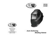
Figure 1. Model H7786.

Identification
A. Delay Time Dial
B. Sensitivity Dial
C. Battery Compartment
D. View Window
E. Variable Shade Dial
F. "ON" Switch
G. Solar Cell
H. Sensor
Figure 2. View of the inside control panel.
Figure 3. View of the left side of helmet.
Figure 4. The front of the helmet.
D
A
B
C
E
F
G
H
H
D
Delay Time
This feature allows you to control how soon the
auto lense reverts back to the #4 shade condition
after you have stopped welding. This can be very
important when the puddle remains very bright
momentarily.
Sensitivity
You can control how sensitive the sensors are to
the arc light. We recommend that the dial be set in
the middle position for most applications.
Battery Compartment
The helmet uses 2 AAA size batteries which are
installed in this compartment. If the helmet is to be
stored for an extended time, remove the batteries
to avoid damage to the compartment.
View Window
This window is set to #4 shade when off or when
the sensors are not exposed to strong light.
Shade Dial
Adjustments can be made to the amount of shad-
ing the view window provides. The range is from
#9 to #13 shade.
"ON" Switch
Push this button once to turn on the auto darken-
ing feature on the helmet. The helmet will turn off
automatically 15 minutes after the sensors have
been exposed to bright light.
Solar Cell
This unit powers some of the components used
by the auto darkening device.

Variable Shade
The shade chart below shows settings that can
be used for various welding processes. We rec
-
ommend that you start ANY welding process at
#12 or #13 and reduce the shade as needed for
safety.
"ON" Switch
Push the "ON" button on the side of the helmet.
The auto darkening feature will activate and stay
active for 15 minutes after the last bright light.
You will need to push the button again when this
occurs. Before welding raise the helmet up to a
bright light source and make sure the auto dark-
ening feature activates. If it does not, push the
button and check again. If it still does not work
see the troubleshooting guide at the end of this
instruction sheet.
Operation
Welding App. Current Amp. Shade No.
Stick Welding
<40
40-80
80-175
175-300
300-500
#9
#10
#11
#12
#13
MIG
(metal inert
gas)
<100
100-175
175-300
300-500
#10
#11
#12
#13
TIG
(tungsten inert
gas)
<50
50-100
100-200
200-400
#10
#11
#12
#13
Air Carbon
Arc
<500
500-700
#12
#13
Plasma
Cutting
60-150
150-250
250-400
#11
#12
#13
Plasma
Welding
<50
50-200
200-400
#9
#10
#11
Sensitivity Dial
As previously mentioned, the auto darkening
lense can be made more sensitive or less sensi
-
tive to bright light produced by welding. In most
applications, the dial should be set to middle of its
range. However, the setting should be changed
when used in extreme conditions. Below is a list
of applications and settings that you can use as a
guide for making adjustments.
Stick Welding Mid Sensitivity
MIG Welding
(short circuit)
Low-Mid Sensitivity
MIG Welding
(pulsed or spray)
Mid Sensitivity
TIG Welding Mid-High Sensitivity
Plasma Cutting/
Welding
Low-Mid Sensitivity

Batteries
To replace the batteries, unclip the cover on
the battery compartment. Be sure to orient the
replacements as described on the compartment
cover or damage could occur to the electronics
in the helmet. Remove the batteries for long term
storage of the helmet.
Maintenance
Lens Cover
The lens cover must be clean to insure the proper
and safe operation of the auto darkening feature.
We recommend that the lens cover be removed
and that it be cleaned with warm soapy water
and a soft cloth. Paper towels, solvents and some
glass cleaners will damage the lens cover, reduc-
ing its effectiveness and safe operation. Replace
damaged lens covers.
Troubleshooting
Symptom Possible Cause Possible Solution
Auto darkening lens does
not darken when "ON"
button is pushed.
1. Batteries are low or dead.
2. Batteries are installed incorrectly.
3. Contact points on batteries are dirty or cor
-
roded.
4. Power cord from the switch to the circuitry is
damaged.
5. Switch is faulty.
6. Auto darkening lens is faulty.
1. Replace batteries with new ones.
2. Remove the batteries and orient them as
shown on the battery compartment cover and
reinstall.
3. Remove the batteries and clean the ends.
Replace corroded batteries with new ones.
4. Contact Grizzly Industrial for repair or replace
-
ment.
5. Contact Grizzly Industrial for repair or replace
-
ment.
6. Contact Grizzly Industrial for repair or replace
-
ment.
Auto darkening lens does
not darken while welding.
1. Batteries are low or dead.
2. Batteries are installed incorrectly.
3. Contact points on batteries are dirty or cor
-
roded.
4. Lens cover is damaged or dirty, impeding the
2 sensors.
5. Sensitivity is set too low.
1. Replace batteries with new ones.
2. Remove the batteries and orient them as
shown on the battery compartment cover and
reinstall.
3. Remove the batteries and clean the ends.
4. Clean or replace the lens cover.
5. Turn the dial for sensitivity all the way up and
test against a bright light. DO NOT weld to
test.
Auto darkening lens does
not stay on or flickers dur
-
ing welding.
1. Sensitivity is set too low. 1. Review sensitivity settings section.

H7786 Parts Breakdown and List
Ref # Part # Description
001 PH7786001 HELMET BODY
002 PH7786002 LENSE COVER
003 PH7786003 AUTO DARKENING LENSE
004 PH7786004 KNOB
005 PH7786005 NUT
006 PH7786006 SCREW
007 PH7786007 FRICTION KNOB
008 PH7786008 HEADBAND
009 PH7786009 FRICTION SCREW
010 PH7786010 TILT STOP BRACKET
011 PH7786011 SWEAT BAND


/