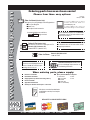
MULTIQUIP Chainsaw MT-74FA User manual
- Category
- Engine
- Type
- User manual
This manual is also suitable for

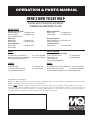
OPERATION AND PARTS MANUAL
Revision #3 (11/08/07)
SERIES
MODEL MT-74FA
TAMPING RAMMER
(ROBIN GASOLINE ENGINE)
THIS MANUAL MUST ACCOMPANY THE EQUIPMENT AT ALL TIMES.
To find the latest revision of this
publication, visit our website at:
www.multiquip.com

PAGE 2 — MT-74FA — OPERATION AND PARTS MANUAL — REV. #3 (11/08/07)
MT-74FA — PROPOSITION 65 WARNING

MT-74FA — OPERATION AND PARTS MANUAL — REV. #3 (11/08/07) — PAGE 3
NOTE PAGE

PAGE 4 — MT-74FA — OPERATION AND PARTS MANUAL — REV. #3 (11/08/07)
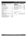
MT-74FA — TABLE OF CONTENTS
Multiquip Tamping Rammer
MT-74FA
Proposition 65 Warning ......................................... 2
Table Of Contents ................................................. 4
Parts Ordering Procedures ................................... 5
Safety Message Alert Symbols .......................... 6-7
Rules For Safe Operation ..................................8-9
Operation and Safety Decals .............................. 10
General Information ............................................ 11
Specifications ...................................................... 12
Controls and Components .................................. 13
Operation .......................................................14-16
Maintenance ....................................................... 17
Troubleshooting Guide ...................................18-19
Explanation Of Codes In Remarks Column ........ 20
Suggested Spare Parts ....................................... 21
Name Plate and Decals .................................22-23
Crankcase and Engine Assembly ..................24-27
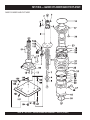
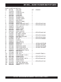
Guide Cylinder and Foot Assembly ...............28-29
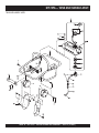
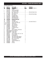
Tank and Handle Assembly ...........................30-33
ROBIN EH-12-2D46420
ENGINE
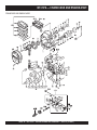
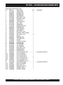
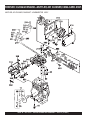
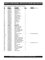
Crankcase and Cylinder Assembly ................34-35
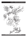
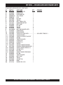
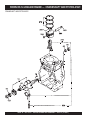
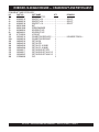
Crankshaft and Piston Assembly ...................36-37
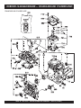
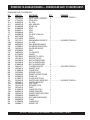
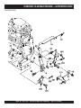
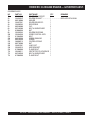
Muffler, Air Cleaner, Camshaft,& Carb. Assy. .38-39
Governor Assembly .......................................40-41
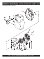
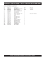
Recoil Starter and Blower Assembly .............42-43
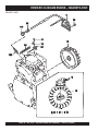
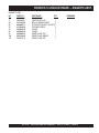
Magneto Assembly ........................................44-45
Carburetor Assembly .....................................46-47
Terms and Condition Of Sale
— Parts ................ 48
Specification and part number are
subject to change without notice.
NOTE

MT-74FA — OPERATION AND PARTS MANUAL — REV. #3 (11/08/07) — PAGE 5
www.multiquip.com
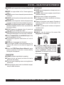
Ordering parts has never been easier!
Choose from three easy options:
WE ACCEPT ALL MAJOR CREDIT CARDS!
When ordering parts, please supply:
❒❒
❒❒
❒
Dealer Account Number
❒❒
❒❒
❒
Dealer Name and Address
❒❒
❒❒
❒
Shipping Address (if different than billing address)
❒❒
❒❒
❒
Return Fax Number
❒❒
❒❒
❒
Applicable Model Number
❒❒
❒❒
❒
Quantity, Part Number and Description of Each Part
❒❒
❒❒
❒
Specify Preferred Method of Shipment:
✓
UPS/Fed Ex
✓ DHL
■
Priority One
✓
Tr uck
■
Ground
■ Next Day
■
Second/Third Day
All orders are treated as
Standard Orders
and will ship the same day if received prior
to 3PM PST.
If you have an MQ Account, to obtain a
Username and Password, E-mail us at:
To obtain an MQ Account, contact you
r
District Sales Manager for more information.
Order via Internet (Dealers Only):
Order parts on-line using Multiquip’s SmartEquip website!
■
View Parts Diagrams
■
Order Parts
■
Print Specification Information
Note: Discounts Are Subject To Change
Goto www.multiquip.com and click on
Order Parts
to log in and save!
Use the
internet
and qualify for a 5% Discount
on
Standard orders
for all orders which include
complete part numbers.*
Order via Fax (Dealers Only):
All customers are welcome to order parts via Fax.
Domestic (US) Customers dial:
1-800-6-PARTS-7 (800-672-7877)
Fax
your order in and qualify for a 2% Discount
on
Standard orders
for all orders which include
complete part numbers.*
Order via Phone:
Domestic (US) Dealers Call:
1-800-427-1244
Best Deal!
International Customers
should contact
their local Multiquip Representatives for
Parts Ordering information.
Non-Dealer Customers:
Contact your local Multiquip Dealer for
parts or call 800-427-1244 for help in
locating a dealer near you.
Note: Discounts Are Subject To Change
Effective:
January 1
st
, 2006

PAGE 6 — MT-74FA — OPERATION AND PARTS MANUAL — REV. #3 (11/08/07)
Safety precautions should be followed
at all times when operating this
equipment. Failure to read and
understand the Safety Messages and
Operating Instructions could result in
injury to yourself and others.
FOR YOUR SAFETY AND THE SAFETY OF OTHERS!
This Owner's Manual has been
developed to provide complete
instructions for the safe and efficient
operation of the MQ Mikasa Model
MT-74FA Tamping Rammer. Refer to
the engine manufacturers instructions
for data relative to its safe operation.
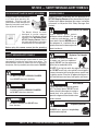
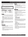
SAFETY MESSAGE ALERT SYMBOLS
The three (3) Safety Messages shown below will inform you
about potential hazards that could injure you or others. The
Safety Messages specifically address the level of exposure to
the operator, and are preceded by one of three words: DANGER,
MT-74FA — SAFETY MESSAGE ALERT SYMBOLS
NOTE
You WILL be
KILLED
or
SERIOUSLY INJURED
if you DO NOT follow these directions.
You CAN be KILLED or
SERIOUSLY INJURED
if
you DO NOT follow these directions.
You CAN be
INJURED
if you DO NOT follow
these directions.
CAUTICAUTI
CAUTICAUTI
CAUTION
DANGERDANGER
DANGERDANGER
DANGER
WARNINGWARNING
WARNINGWARNING
WARNING
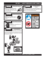
Lethal Exhaust Gases
HAZARD SYMBOLS
Potential hazards associated with the operation of a
MT-74FA Tamping Rammer
will be referenced with Hazard
Symbols which appear throughout this manual, and will be
referenced in conjunction with Safety Message Alert
Symbols.
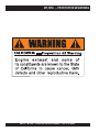
Engine exhaust gases contain
poisonous carbon monoxide. This gas
is colorless and odorless, and can
cause death if inhaled. NEVER operate
this equipment in a confined area or
enclosed structure that does not provide
ample free flow air.
Gasoline is extremely flammable, and
its vapors can cause an explosion if
ignited. DO NOT start the engine near
spilled fuel or combustible fluids.
DO NOT fill the fuel tank while the engine is running or
hot. DO NOT overfill tank, since spilled fuel could ignite if
it comes into contact with hot engine parts or sparks from
the ignition system. Store fuel in approved containers, in
well-ventilated areas and away from sparks and flames.
Engine components can generate extreme
heat. To prevent burns, DO NOT touch
these areas while the engine is running or
immediately after operations. Never
operate the engine with heat shields or heat
guards removed.
ALWAYS wear approved
respiratory
protection when required.
Lethal Exhaust Gas Hazards
WARNINGWARNING
WARNINGWARNING
WARNING
Explosive Fuel Hazards
WARNINGWARNING
WARNINGWARNING
WARNING
Burn Hazards
WARNINGWARNING
WARNINGWARNING
WARNING
Respiratory Hazards
WARNINGWARNING
WARNINGWARNING
WARNING
Before using this rammer, ensure that the operating
individual has read and understands all instructions in this
manual.

MT-74FA — OPERATION AND PARTS MANUAL — REV. #3 (11/08/07) — PAGE 7
MT-74FA — SAFETY MESSAGE ALERT SYMBOLS
ALWAYS place the ON/OFF switch in
the OFF position when the rammer is
not in use.
ALWAYS wear approved eye and
hearing protection.
NEVER operate equipment with covers,
or guards removed. Keep fingers, hands,
hair and clothing away from all moving
parts to prevent injury.
Rotating Parts Hazards
CAUTIONCAUTION
CAUTIONCAUTION
CAUTION
Accidental Starting Hazards
CAUTIONCAUTION
CAUTIONCAUTION
CAUTION
Eye and Hearing Hazards
CAUTIONCAUTION
CAUTIONCAUTION
CAUTION
Other important messages are provided throughout this
manual to help prevent damage to your light tower, other
property, or the surrounding environment.
Equipment Damage
Hazards
CAUTIONCAUTION
CAUTIONCAUTION
CAUTION
NEVER refuel rammer when placed in truck bed with
plastic liner. The possibility exists of explosion due to static
electricity. When adding fuel, remove rammer from truck
bed and place on ground.
Refueling Hazard
DANGERDANGER
DANGERDANGER
DANGER

PAGE 8 — MT-74FA — OPERATION AND PARTS MANUAL — REV. #3 (11/08/07)
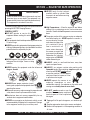
The following safety guidelines should always be used when
operating the MT-74FA Tamping Rammer:
GENERAL SAFETY
■
DO NOT operate or service this
equipment before reading this entire
manual.
■
This equipment should not be operated by persons under
18 years of age.
■
NEVER operate this equipment without proper protective
clothing, shatterproof glasses, steel-toed boots and other
protective devices required by the job.
■
High Temperatures – Allow the engine to cool before
adding fuel or performing service and maintenance
functions. Contact with
hot!
components can cause serious
burns.
■
The engine section of this rammer requires an adequate
free flow of cooling air.
NEVER
operate the rammer in
any enclosed or narrow
area where free flow of the
air is restricted. If the air
flow is restricted it will
cause serious damage to
the rammer or engine and
may cause injury to people.
Remember the rammer's
engine gives off
DEADLY
carbon monoxide gas.
■
ALWAYS refuel in a well-ventilated area, away from
sparks and open flames.
■
ALWAYS use extreme caution when working with
flammable liquids. When refueling, stop the engine and
allow it to cool. DO NOT
smoke
around
or near the machine. Fire or explosion
could result from fuel vapors, or if fuel
is spilled on a hot engine.
■
NEVER operate the rammer in an
explosive atmosphere or near
combustible materials. An explosion or fire could result
causing severe
bodily harm or even death.
DANGERDANGER
DANGERDANGER
DANGER
Failure to follow instructions in this manual may lead
to serious injury or even death! This equipment is to
be operated by trained and qualified personnel only!
This equipment is for industrial use only.
■
NEVER operate this equipment under the influence of
drugs
or
alcohol
.
Read this manual!
■
NEVER touch the hot exhaust
manifold, muffler or cylinder. Allow
these parts to cool before servicing
engine or rammer.
■
ALWAYS wear proper respiratory (mask),
hearing and eye protection equipment when
operating the rammer.
■
Whenever necessary, replace nameplate, operation and
safety decals when they become difficult read.
■
Manufacturer does not assume responsibility for any
accident due to equipment modifications.
■
NEVER use accessories or attachments, which are not
recommended by Multiquip for this equipment. Damage
to the equipment and/or injury to user may result.
■
NEVER operate this equipment when not
feeling well due to fatigue, illness or taking
medicine.
MT-74FA — RULES FOR SAFE OPERATION
■
Topping-off to filler port is dangerous, as it tends to spill
fuel.
■
Stop the engine when leaving the rammer unattended.
■
Maintain this equipment in a safe operating condition at
all times.
■
DO NOT
smoke
around or near the
machine. Fire or explosion could result
from fuel vapors, or if fuel is spilled on a
hot engine.

MT-74FA — OPERATION AND PARTS MANUAL — REV. #3 (11/08/07) — PAGE 9
■
ALWAYS stop the engine before servicing, adding fuel and
oil.
■
NEVER run engine without air filter. Severe engine may
occur.
■
ALWAYS service air cleaner frequently to prevent carburetor
malfunction.
■
ALWAYS check the machine for loosened threads or bolts
before starting.
■
ALWAYS be sure the operator is familiar with proper safety
precautions and operations techniques before using rammer.
■
ALWAYS store equipment properly when it is not being used.
Equipment should be stored in a clean, dry location out of
the reach of children.
■
DO NOT operate this equipment unless all guards and
safety devices are attached and in place.
■
CAUTION must be exercised while servicing this equipment.
Rotating and moving parts can cause injury if contacted.
■
Keep all
inexperienced
and
unauthorized
people away
from the equipment at all times.
■
Unauthorized equipment modifications will void all
warranties.
■
NEVER pour or spray water over the engine.
■
Test the engine ON
/OFF
switch before operating. The
purpose of this switch is to shut down the engine of the
rammer.
■
Refer to the
ROBIN Engine Owner's Manual
for engine
technical questions or information recommended by
Multiquip for this equipment.
TRANSPORTING
■
ALWAYS shutdown engine before transporting.
■
Tighten fuel tank cap securely and close fuel cock to
prevent fuel from spilling.
■
Drain fuel when transporting rammer over long distances
or bad roads.
■
When placing the rammer inside a truck-bed for transport,
always tie-down the rammer
MAINTENANCE
■
NEVER lubricate components or attempt service on a
running rammer.
■
ALWAYS allow the rammer a proper amount of time to
cool before servicing.
■
Keep the rammer in proper running condition.
■
Fix damage to the rammer immediately and always
replace broken parts.
■
Dispose of hazardous waste properly. Examples of
potentially hazardous waste are used motor oil, fuel
and fuel filters.
■
DO NOT use food or plastic containers to dispose of
hazardous waste.
MT-74FA — RULES FOR SAFE OPERATION
■
In emergencies
always
know the location of
the nearest phone or
keep a phone on the job
site
. Also know the phone numbers of the
nearest
ambulance
,
doctor
and
fire
department
. This information will be invaluable
in the case of an emergency.
EMERGENCIES
■
ALWAYS know the location of the nearest
fire
extinguisher
and first aid kit.

PAGE 10 — MT-74FA — OPERATION AND PARTS MANUAL — REV. #3 (11/08/07)
MT-74FA — OPERATION AND SAFETY DECALS
Machine Safety Decals
The MQ Mikasa tamping rammer is equipped with a number of safety decals. These decals are provided for operator safety and
maintenance information. Figure 1 and 1A below and preceeding page illustrates these decals as they appear on the machine.
Should any of these decals become unreadable, replacements can be obtained from your dealer.
Figure 1. Rammer Operation and Safety Decals

MT-74FA — OPERATION AND PARTS MANUAL — REV. #3 (11/08/07) — PAGE 11
MT-74FA — OPERATION AND SAFETY DECALS
Figure 1A. Rammer Operation and Safety Decals

PAGE 12 — MT-74FA — OPERATION AND PARTS MANUAL — REV. #3 (11/08/07)
Definition of Tamping Rammer
The Mikasa MT-74FA tamping rammer is a powerful compacting
tool capable of applying a tremendous force in consecutive
impacts to a soil surface. Its applications include soil compacting
for road, embankments and reservoirs as well as backfilling for
gas pipelines, water pipelines and cable installation work.
The impact force of the MT-74FA levels and uniformly compacts
voids between soil particles to increase dry density.
Circular motion is converted to create impact force. The MT-74FA
tamping rammer develops a powerful compacting force at the
foot of the rammer. To maintain optimum performance, proper
operation and service are essential.
Construction of Tamping Rammer
The Mikasa MT-74FA is equipped with an air-cooled, 4-cycle
gasoline engine. Transmission of the power takes place by
increasing the engine speed to engage the centrifugal clutch.
Rammer Gearbox and Spring Cylinder
The Mikasa MT-74FA uses an oil bath lubrication system. Always
check the oil level through the oil level sight glass at the rear of
the tamper foot.
Controls
Before starting the MT-74FA Tamping Rammer, identify and
understand the function of the controls. See Figure 2.
MT-74FA — GENERAL INFORMATION
Handle Operation
CAUTIONCAUTION
CAUTIONCAUTION
CAUTION
Before starting operation check the lifting
handle to:
1. Make sure that there is no damage on the bolts.
2. Make sure that there is no crack or breakage on handle.
3. Make sure that there is no fissure on the surface. If there
is any abnormality or damage, replace with new one.
For operation:
This handle is to be used to lift up the shoe part of the machine
with the body laid down on the ground or truck bed.
1. Use proper lifting techniques to avoid back injury. This
handle is for manual lifting only.
2. Do not use this handle as a rammer lift point. Use the
lifting point on the top of the machine.
3. Do not move the rammer with the lifting handle and the
front rollers more than (16 feet) 5 meters.

MT-74FA — OPERATION AND PARTS MANUAL — REV. #3 (11/08/07) — PAGE 13
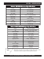
MT-74FA — SPECIFICATIONS
snoitacificepSremmaRAF47-TM.1elbaTsnoitacificepSremmaRAF47-TM.1elbaT
snoitacificepSremmaRAF47-TM.1elbaT
snoitacificepSremmaRAF47-TM.1elbaTsnoitacificepSremmaRAF47-TM.1elbaT
LEDOMAF47-TM
thgieHllarevO)mm5501(ni5.14
htdiWllarevO)mm014(ni1.61
htgneLrevO)mm537(ni9.82
)WxL(eziSeohS)mm582
x043(ni2.11x4.31
etunim/swolB086-046
ecroFtcapmI)gk004,1(bl001,3
ekortS)mm08(.ni51.3
deepSlevarT)nim/m21-9(ni
m/tf4.93-5.92
thgieWgnitarepO)gk18(sbl971
Specifications are general and are subject to change without notice. If exact
measurements are required, equipment should be weighed and measured.
NOTE
snoitacificepSenignE02464D2-21HE.2elbaTsnoitacificepSenignE02464D2-21HE.2elbaT
snoitacificepSenignE0246
4D2-21HE.2elbaT
snoitacificepSenignE02464D2-21HE.2elbaTsnoitacificepSenignE02464D2-21HE.2elbaT
LEDOM02464D2-21HENIBOR
epyTenignEenilosaGekortS4delooC-riA
tnemecalpsiDnotsiPmc121(.ni.uc83.7
3
)
tuptuO.xaM)wk6.2(PH5.3
deepSgnitteSmpr006,3-004,3
metsySgnilooCdelooC-riA
metsySnoitacirbuLliOrotoM03W01-htaBliO
yticapaCknaTliO)retil4.0(tnip8.0
leuFenilosagdedaelnU
yticapaCknaTleuF)sretil2(trauq1.2
metsySgnitratSr
etratSlioceR
metsySroterubraCmgarhpaiD

PAGE 14 — MT-74FA — OPERATION AND PARTS MANUAL — REV. #3 (11/08/07)
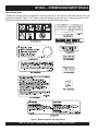
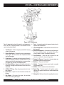
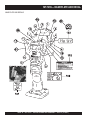
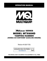
Figure 2 shows the location of the controls and components
for the MT-74FA Tamping Rammer. The functions of each
control is described below:
L1. A Returned Material Authorization must be approved by Multiquip prior to shipment. A copy of the Authorization must
accompany the shipment to the designated Warehouse. A copy of the original Multiquip invoice to the customer must
also accompany the shipment.
1. Throttle Lever – Controls engine speed and the tamping
action of the rammer.
2. Engine Stop Switch – Controls the starting and stopping
of the engine. Switch must be in the "ON" position when
starting the engine.
3. Choke Lever – Used when starting the engine. Normally
used in cold weather conditions. In cold weather turn the
choke lever to the fully closed position, in warm weather
set choke lever half way or completely open.
4. Fuel Shut-Off Valve – Supplies fuel from the fuel tank to
the engine. To begin fuel flow move the fuel shut-off valve
downward.
5. Oil Bath Fill Plug – Open this plug to add oil to the oil
bath reservoir.
6. Drain Valve – Open this valve to remove oil from the
bellows.
7. Pre-Cleaner – Pre-cleans (first stage) dirt and other
debris from entering the engine.
8. Foot – Laminated wood with tempered steel plate for
superior shock absorption.
9. Oil Level Sight Glass – Indicates the level of oil in the oil
bath reservoir.
10. Recoil Starting Handle – Used when starting the engine.
Pull starter handle sharply and quickly, then return
starter handle to starter case before releasing.
11. Fuel Tank/Cap – Poly fuel tank to avoid rust and
corrosion, remove this cap to add gasoline.
12. Engine Air Cleaner – Prevents dirt (second stage) and
other debris from entering the engine.
13. Bellows – Reservoir for oil bath.
14. Handle – To operate rammer, grip
handle assembly
firmly on both sides.
15. Muffler– Used to reduce noise and emissions.
16. Spark Plug – Provides spark to the ignition system,
replace with engine manufactures recommended type
spark plug.
17. Nameplate – Displays information regarding the rammer.
Figure 2. MT-74FA Rammer
MT-74FA — CONTROLS AND COMPONENTS

MT-74FA — OPERATION AND PARTS MANUAL — REV. #3 (11/08/07) — PAGE 15
MT-74FA — BASIC ENGINE
WARNING
WARNING
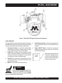
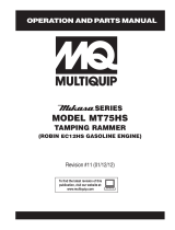
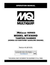
Figure 3. Robin EH-12-2D Engine Controls and Components
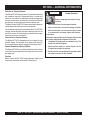
INITIAL SERVICING
The engine (Figure 3) must be checked for proper lubrication and
filled with fuel prior to operation. Refer to the manufacturer's Engine
manual for instructions & details of operation and servicing.
1. Secondary Air Cleaner – Prevents dirt and other debris
from entering the fuel system. Remove wing-nut on top of
air filter cannister to gain access to filter element.
2. Choke Lever –Used when starting the engine. Normally
used in cold weather conditions. In cold weather turn the
choke lever to the fully closed position, in warm weather
set choke lever half way or completely open.
3. Spark Plug – Provides spark to the ignition system. Set
spark plug gap to 0.6 - 0.7 mm (0.024 - 0.028 inch). Clean
spark plug once a week.
4. Muffler – Used to reduce noise and emissions.
Operating the engine without an
air filter, with a damaged air filter,
or a filter in need of replacement
will allow dirt to enter the engine,
causing rapid engine wear.
5. Recoil Starter (pull rope) – Manual-starting method. Pull
the starter grip until resistance is felt, then pull briskly and
smoothly.
6. Engine ON/OFF Switch – Controls the starting and
stopping of the engine. Switch must be in the "ON" position
when starting the engine.
NOTE
WARNING
Engine components can generate extreme heat.
To prevent burns, DO NOT touch these areas
while the engine is running or immediately after operating. NEVER
operate the engine with the muffler removed.

PAGE 16 — MT-74FA — OPERATION AND PARTS MANUAL — REV. #3 (11/08/07)
Failure to understand the operation of
the MT-74FA Tamping Rammer could
result in severe damage to the trowel
or personal injury.
Rammer Gearbox and Spring Cylinder Oil Bath
This unit uses an oil bath lubrication system. Perform the following:
1. Check the oil level through the oil level sight glass (Figure 4)
at the rear of the tamper foot.
This section is intended to assist the operator with the initial
start-up of the MT-74FA Tamping Rammer. It extremely important
that this section be read carefully before attempting to operate
the rammer.
DO NOT use your rammer until this section is thoroughly
understood.
The oil level should be kept at the half
way point of the sight glass.
2. Low levels of oil may result in engine seizure due to high
levels of consumption during operations.
3. Check the engine oil level and if the engine oil level is low, it
should be refilled. Use the proper motor oil as suggested in
the Table 3 below.
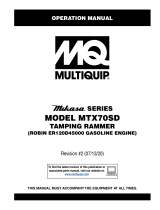
Figure 6. Engine Oil Dipstick
Figure 4. Foot Housing Sight Glass
2. If oil is not visible, add 10W-30 motor oil into the oil fill plug
opening (Figure 4). The bath contains approximately 0.8
pints (0.4 liters)
Figure 5. Fuel Tank
Engine
1. Fill the fuel tank (Figure 5) with unleaded gasoline. At the
same time, check the engine oil and make it a habit to
replenish it often.
MT-74FA — OPERATION
edarGliOrotoM3elbaT
erutarepmeTronosaeS
liorotomfoedarG
)ssalcSMnahtrehgih(
nmutuAroremmuS,gnirpS
F°51+otF°021+
03EAS
retniW
F°5
1+otF°04+
03EAS
F°51+woleB03-W01EAS
NOTE
CAUTICAUTI
CAUTICAUTI
CAUTION
Read Manual

MT-74FA — OPERATION AND PARTS MANUAL — REV. #3 (11/08/07) — PAGE 17
MT-74FA — OPERATION
Inspection
1 . Check all nuts, bolts fasteners for tightness. Retighten as
necessary.
2. Clean any dirt from the recoil starter and foot pedestal. Wipe
the entire unit clean before operating.
3. Replace any missing or damaged Safety Operation decals.
4. Adjust height of handle. Adjust handle by loosening nuts and
moving handle to suit operation. Retighten nuts.
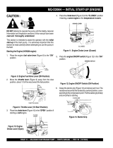
Initial Start-up
When starting the MT-74FA Tamping Rammer perform the
following:
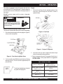
1. Open the fuel shut-off valve by moving the
fuel cock
lever
to the
open
position (Figure 7) then set the engine start/
stop switch (Figure 6) to the "START" position.
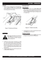
3. Close the choke lever (Figure 9) and move the throttle lever
to the "Full Open" position. Turning the choke lever 90
degrees clockwise closes the choke . In cold weather, start the
unit with choke fully closed. In warm weather or when the
engine is warm, the unit can be started with choke halfway
or completely open.
Figure 8. On Off Switch
Figure 7. Fuel Cock
2. Set the engine ON/OFF switch (Figure 8) to the "ON"
position (start).
Figure 9. Choke Lever
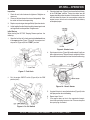
4. Grip the recoil starter (Figure10) handle and pull it until you
feel a slight resistance. Then pull sharply and quickly. Return
the recoil starter handle to the starter case before releasing.
5. If engine fails to start, move the choke lever (Figure 9) to the
half open position to avoid flooding.
6. Repeat steps 1 thru 4.
7. If the engine does not start after repeated attempts,
check the spark plug for excess fuel. Clean and replace
the spark plug as needed.
Figure 10. Recoil Starter

PAGE 18 — MT-74FA — OPERATION AND PARTS MANUAL — REV. #3 (11/08/07)
Operation
1. To start the rammer tamping action, move the throttle lever
(Figure 11) quickly from IDLE (close) to the FULL OPEN
position . DO NOT move the throttle lever slowly as this may
cause damage to the clutch or spring.
Stopping The Engine
Normal Shutdown
1. Move throttle lever quickly from the FULL OPEN to IDLE
position (Figure 12) and run the engine for three minutes at
low speed. After the engine
cools
, turn the engine start/stop
switch to the “STOP” position (Figure 8) until engine comes
to a complete stop.
2. Close the fuel shut- off valve by moving the fuel cock lever to
the CLOSED position. See Figure 5.
Emergency Showdown
1. Move the throttle lever quickly to the
IDLE
position, and turn
the engine start/stop switch to the
STOP
position.
Figure 12. Throttle Lever (Idle)
MT-74FA — OPERATION
CAUTION:CAUTION:
CAUTION:CAUTION:
CAUTION:
Make sure that the throttle lever is moved to the
FULL OPEN position. Operating the rammer at
less than full speeds can result in damage to
the clutch springs or foot
2. The MT-74FA tamping rammer is designed to run at 4,000
rpm. At optimum rpm the foot hits at the rate of 680 impacts
per minute. Increasing throttle speed past factory set rpm
does not increase impacts and may damage unit. The
MT-74FA is designed to advance while tamping. For faster
advance, pull back slightly on the handle so that rear of foot
contacts soil first.
3. To stop the tamping action, move throttle lever quickly from
the FULL OPEN to IDLE position.
Figure 11. Throttle Lever (Full Open)

MT-74FA — OPERATION AND PARTS MANUAL — REV. #3 (11/08/07) — PAGE 19
Maintenance
Perform the scheduled maintenance procedures as indicated:
DAILY
■
Thoroughly remove dirt and oil from the engine and control
area. Clean or replace the air cleaner elements as necessary.
Check and retighten all fasteners as necessary. Check the
spring box and bellows for oil leaks. Repair or replace as
needed.
WEEKLY
■
Remove the fuel filter cap and clean the inside of the fuel
tank.
■
Remove or clean the filter at the bottom of the tank.
■
Remove and clean the spark plug, then adjust the spark gap
to 0.02~0.03 inch (0.6~0.7 mm). This unit has electronic
ignition, which requires no adjustments.
■
Clean air cleaner cover.
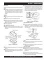
200 - 300 HOURS (Pre-Cleaner)
■
Remove the element from the pre-cleaner (Figure 11) at the
top of the crankcase (body side) and clean it with cleaning oil
(kerosene).
MT-74FA — MAINTENANCE
Figure 11. Pre-Cleaner
■
Lubricate the top element (yellow) with 2~5 cc of engine oil
SAE-30.
■
Lubricate bottom element (gray) with 13 ~15 cc of engine oil
SAE-30 and completely squeeze out the excess oil from the
element before installing.
200 - 300 HOURS (Oil Bath)
■
Drain oil reservoir on foot housing (Figure 13). Refill with
approximately 1.7 pt. (800cc) of 10W-30 motor oil. Oil should
be midway in sight glass. Break in oil should be changed
after first 50 hours.
■
The air cleaner (Figure 12 ) on the engine side will hardly
be contaminated, if it is, however after cleaning the element
with kerosene, dip it in mixed oil consisting of 3 parts of
gasoline and 1 part of engine oil. Then tightly squeeze outer
primary element (sponge) and shake off well the inner
secondary element before installing them.
Figure 12. Engine Air Cleaner
Yearly
■
Check the fuel line and the oil line regularly for damage and
to ensure that there are no leaks.
■
Replace the oil and fuel lines every two years to maintain the
performance and flexibility lines.
Long Term Storage
■
Drain fuel from fuel tank, fuel line and carburetor.
■
Remove spark plug and pour a few drops of motor oil into
cylinder. Crank engine 3 to 4 times so that oil reaches all
internal parts.
■
Clean exterior with a cloth soaked in clean oil.
■
Store unit covered with plastic sheet in moisture free and
dust free location out of direct sunlight
Figure 13. Foot Housing Drain Plug
YELLOW
GRAY
13 -15 CC
SAE 30
2-5 CC
SAE 30
PRE-CLEANER

PAGE 20 — MT-74FA — OPERATION AND PARTS MANUAL — REV. #3 (11/08/07)
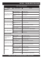
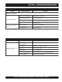
MT-74FA — TROUBLESHOOTING GUIDE
GNITOOHSELBUORTENIGNE.4ELBAT
MOTPMYS MELBORPELBISSOP NOITULOS
tratsottluciffiD
gulpkrapstubelbaliavasileuF
elbaliavarewoP(.etingitonlliw
.)elbacnoisnethgihta
?egdirbgniebgulpnoitingI .metsysnoitingikcehC
?noitingitatisopednobraC .noitingiecalperronaelC
evitcefedoteudtiucrictrohS
?srotalusni
.srotalusniecalpeR
?pagkrapsreporpmI .pagtcerrocehtotpaggulpkrapsteS
gulpkrapstubelbaliavasileuF
rewoP(.etingitonlliw
TON
.)elbacnoisnethgihtaelbaliava
?hctiwspotstatiucrictrohS .evitcefedfihctiwspotsecalpeR.tiucrichctiwspotskcehC
?evitcefedliocnoitingI .liocnoitingiecalpeR
gulpkrapsdnaelbaliavasileuF
noisserpmoc(setingi
)lamron
.
nobrachtiwdeggolcrelffuM
?stisoped
.relffumecalperronaelC
,retaw(etauqedaniesunileuF
?)tsud
.leufhserfhtiwecalperdnametysleufhsulF
?deggolcrenaelCriA .renaelcriaecalperronaelC
gulpkrapsdnaelbaliavasileuF
noisserpmoc(setingi
wol
.)
?teksagdaehrednilycevitcefeD .teksagdaehecalperrostlobdaehrednilycnethgiT
?nrowrednilyC .rednilycecalpeR
?esoolgulpkrapS .gulpkrapsnehgiT
yrotcafsitastonnoitarepO
elbaliavarewophguonetoN
on,lamronnoisserpmoc(
.)gnirifsim
?deggolcrenaelcriA .renaelcriaecalperronaelC
?enilleufniriA .enilleufmorf)riaevomer(deelB
?rednilycnistisopednobraC .rednilycecalperronaelC
elbaliavarewophguonetoN
.)gnirifsim,lamronnoisserpmoc(
?evitcefedliocnoitingI .leufhserfhtiwecalperdnametysleufhsulF
?strohsnetfogulpnoitingI .noitinginaelc,seriwnoitingiecalpeR
,retaw(etauqedaniesunileuF
?)tsud
.leufhserfhtiwecalperdnametysleufhsulF
.staehrevoenignE
?etauqedanisiytilauqleufdeniM .erutximliootleufkcehC
nistisopednobracevissecxE
?rebmahcnoitsubmoc
.esacknarcecalperronaelC
htiwdeggolcrelffumrotsuahxE
?nobrac
.relffumecalperronaelC
?tcerrocnieulavtaehgulpkrapS .gulpkrapsepyttcerrochtiwgulpkrapsecalpeR
Page is loading ...
Page is loading ...
Page is loading ...
Page is loading ...
Page is loading ...
Page is loading ...
Page is loading ...
Page is loading ...
Page is loading ...
Page is loading ...
Page is loading ...
Page is loading ...
Page is loading ...
Page is loading ...
Page is loading ...
Page is loading ...
Page is loading ...
Page is loading ...
Page is loading ...
Page is loading ...
Page is loading ...
Page is loading ...
Page is loading ...
Page is loading ...
Page is loading ...
Page is loading ...
Page is loading ...
Page is loading ...
Page is loading ...
Page is loading ...
-
 1
1
-
 2
2
-
 3
3
-
 4
4
-
 5
5
-
 6
6
-
 7
7
-
 8
8
-
 9
9
-
 10
10
-
 11
11
-
 12
12
-
 13
13
-
 14
14
-
 15
15
-
 16
16
-
 17
17
-
 18
18
-
 19
19
-
 20
20
-
 21
21
-
 22
22
-
 23
23
-
 24
24
-
 25
25
-
 26
26
-
 27
27
-
 28
28
-
 29
29
-
 30
30
-
 31
31
-
 32
32
-
 33
33
-
 34
34
-
 35
35
-
 36
36
-
 37
37
-
 38
38
-
 39
39
-
 40
40
-
 41
41
-
 42
42
-
 43
43
-
 44
44
-
 45
45
-
 46
46
-
 47
47
-
 48
48
-
 49
49
-
 50
50


MULTIQUIP Chainsaw MT-74FA User manual
- Category
- Engine
- Type
- User manual
- This manual is also suitable for
Ask a question and I''ll find the answer in the document
Finding information in a document is now easier with AI
Related papers
-
 MULTIQUIP MT55F User manual
-
 MULTIQUIP MT-62HS User manual
-
 MULTIQUIP GX390K1SM32 User manual
-
 MULTIQUIP MT-86D2 User manual
-
 MQ Multiquip MTX70HD Installation guide
-
 MULTIQUIP MT-86D User manual
-
 MULTIQUIP MQ-D206H User guide
-
 MULTIQUIP MT-84F User manual
-
 MULTIQUIP Drums MT75HS User manual
-
 MULTIQUIP Drums MTR40SF User manual


Other documents
-
 MQ Multiquip MT74FA Operating instructions
-
 MQ Multiquip MT55F Operating instructions
-
 MQ Multiquip MT85HS Operating instructions
-
 MQ Multiquip MTX60HF Operating instructions
-
 MQ Multiquip MTR40HF Operating instructions
-
 MQ Multiquip MT74FAF Operating instructions
-
 MQ Multiquip MTX60HD Operating instructions
-
 MQ Multiquip MT62HS Operating instructions
-
 MQ Multiquip MTX50HD Operating instructions
-
 MQ Multiquip MTX70SD Operating instructions


