
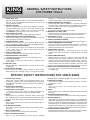
GENERAL SAFETY INSTRUCTIONS
FOR POWER TOOLS
1. KNOW YOUR TOOL
Read and understand the owners manual and labels affixed to
the tool. Learn its application and limitations as well as its
specific potential hazards.
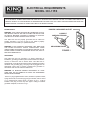
2. GROUND THE TOOL.
This tool is equipped with an approved 3-conductor cord and a
3-prong grounding type plug to fit the proper grounding type
receptacle. The green conductor in the cord is the grounding
wire.
NEVER connect the green wire to a live terminal.
3. KEEP GUARDS IN PLACE.
Keep in good working order, properly adjusted and aligned.
4. REMOVE ADJUSTING KEYS AND WRENCHES.
Form habit of checking to see that keys and adjusting wrenches
are removed from tool before turning it on.
5. KEEP WORK AREA CLEAN.
Cluttered areas and benches invite accidents. Make sure the
floor is clean and not slippery due to wax and sawdust build-up.
6. AVOID DANGEROUS ENVIRONMENT.
Don’t use power tools in damp or wet locations or expose them
to rain. Keep work area well lit and provide adequate
surrounding work space.
7. KEEP CHILDREN AWAY.
All visitors should be kept a safe distance from work area.
8. MAKE WORKSHOP CHILD-PROOF.
-with padlocks, master switches or by removing starter keys.
9. USE PROPER SPEED.
A tool will do a better and safer job when operated at the
proper speed.
10. USE RIGHT TOOL.
Don’t force the tool or the attachment to do a job for which it was
not designed.
11. WEAR PROPER APPAREL.
Do not wear loose clothing, gloves, neckties or jewelry (rings,
watch) because they could get caught in moving parts. Non-slip
footwear is recommended. Wear protective hair covering to
contain long hair. Roll up long sleeves above the elbows.
12. ALWAYS WEAR SAFETY GLASSES.
Always wear safety glasses (ANSI Z87.1). Everyday eyeglasses
only have impact resistant lenses, thet are
NOT safety glasses.
Also use a face or dust mask if cutting operation is dusty.
13. DON’T OVERREACH.
Keep proper footing and balance at all times.
14. MAINTAIN TOOL WITH CARE.
Keep tools sharp and clean for best and safest performance.
Follow instructions for lubricating and changing accessories.
15. DISCONNECT TOOLS.
Before servicing, when changing accessories or attachments.
16. AVOID ACCIDENTAL STARTING.
Make sure the switch is in the ‘’OFF’’ position before plugging in.
17. USE RECOMMENDED ACCESSORIES.
Consult the manual for recommended accessories. Follow the
instructions that accompany the accessories. The use of
improper accessories may cause hazards.
18. NEVER STAND ON TOOL.
Serious injury could occur if the tool tips over. Do not store
materials such that it is necessary to stand on the tool to reach
them.
19. CHECK DAMAGED PARTS.
Before further use of the tool, a guard or other parts that are
damaged should be carefully checked to ensure that they will
operate properly and perform their intended function. Check for
alignment of moving parts, breakage of parts, mounting, and any
other conditions that may affect its operation. A guard or other
parts that are da -maged should be properly repaired or replaced.
20. NEVER LEAVE MACHINE RUNNING UNATTENDED.
Turn power ‘’OFF’’. Don’t leave any tool running until it comes to
a complete stop.
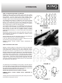
1. ALWAYS USE A GUARD.
Always use a guard, splitter and anti-kickback fingers on all
“thru-sawing” operations. Thru-sawing operations are those when
the blade cuts completely through the workpiece as in ripping or
crosscutting.
2. ALWAYS HOLD THE WORK.
Always hold the work firmly against the miter gauge or fence.
3. ALWAYS USE A PUSH STICK.
For ripping narrow stock. Refer to ripping applications in
instruction manual where push sticks are covered in detail.
4. NEVER.
Never perform any operations “free-hand” which means using
your hands to support or guide the workpiece. Always use either
the fence or the miter gauge to position and guide the workpiece.
5. NEVER.
Never stand or have any part of your body in line with the path of
the saw blade.
6. NEVER REACH BEHIND.
Never reach behind or over the cutting tool with either hand for
any reason.
7. MOVE THE RIP FENCE.
Move the rip fence out of the way when crosscutting.
8. WHEN CUTTING MOULDINGS.
Never run the stock between the fence and the moulding
cutterhead. Refer to moulding applications in the manual for details.
9. DIRECTION OF FEED.
Feed work into the blade or cutter against the direction or rotation
of the blade or cutter.
10. NEVER.
Never use the fence as a cut-off gauge when you are
crosscutting.
11. NEVER.
Never attempt to free a stalled saw blade without first turning the
saw OFF.
12. PROVIDE ADEQUATE SUPPORT.
To the rear and sides of the table saw for wide or long workpieces.
13. AVOID KICKBACKS.
Avoid kickbacks (work thrown back towards you) by keeping the
blade sharp, by keeping the rip fence parallel to the saw blade, by
keeping the splitter and anti-kickback fingers and guard in place
and operating, by nor releasing work before it is pushed all the
way past the saw blade, and by not ripping work that is twisted or
warped or does not have a straight edge to guide along the fence.
14. AVOID AWKWARD OPERATIONS.
A
void awkward operations and hand positions where a sudden
slip could cause your hand to move into the cutting tool.
SPECIFIC SAFETY INSTRUCTIONS FOR TABLE SAWS


 1
1
 2
2
 3
3
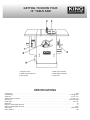 4
4
 5
5
 6
6
 7
7
 8
8
 9
9
 10
10
 11
11


King Canada KC-10FX User manual
King Industrial KC-10GC User manual
King Canada KC-10KX/U50 User manual
Stanley STST1825 User manual
Hitachi C 10FR User manual
 Tradesman BTS10BW Owner's manual
COMPANION 137232040 Owner's manual
Craftsman 137221940 Owner's manual
Rikon Power Tools 11-300 User manual
