Page is loading ...

3M™ 3-Conductor In-line Splice Kits,
5750 Series
For Armored or Non-armored Cables 1000 Volts or Less
Installation Instructions
Kit Contents:
5751 5752 5753 5751 5752 5753
2 3 4 Spacer Webs 3 3 3 Cold Shrink Insulator Assemblies
2 7* 16
Size C Bags 3M™ Scotchcast™ Flame-Retardant
Compound 2131
1 1 2 Roll(s) Scotch® Electrical Semi-conducting Tape 13
1 1 2 Roll(s) Scotch® Linerless Rubber Splicing Tape 130C
1 1 1
Strip 3M™ Three-M-Ite™ Elek-Tro-Cut™ Abrasive Cloth
80J Grit
2 2 2 Strips Scotch® Electrical Shielding Tape 24
1 1 1 Wrap-around Mold 1 1 1 Roll Scotch® Super 33+™ Vinyl Electrical Tape
2 2 3 Mold Straps 1 1 1 3M™ Cable Cleaning Preparation Kit CC-2
2 2 3 Funnels 1 1 1 Coil of Scotch® Electrical Grounding Braid 25
2 2 3 Funnel Supports 2 2 2 Constant Force Springs
*6 Size C and 1 Size B
Main Illustration
(Larger image on page 2)
DANGER: BEFORE ATTEMPTING ANY CABLE REPAIRS, MAKE SURE THAT THE PROPER CABLE IS DISCONNECTED, LOCKED OUT AND
SUITABLY TAGGED.
Technical Information:
For use on armored or non-armored 3-conductor cables:
1000 Volts or Less: Copper 6 AWG-750 kcmil
Aluminum 6 AWG-750 kcmil
Mine Safety and Health Administration Acceptance: 07-KA060007-MSHA
August, 2011
3
78-8126-9795-7 A
1 of 11

Main Illustration
78-8126-9795-7 A
2 of 11

3 of 11
Kit No.
Insulation
O.D. Range
1 kV Conductor Sizes
Copper or Aluminum
5751
0.50 – 0.95 in.
(13 – 24 mm)
1 – 3/0 AWG
(50 – 95 mm
2
)
5752
0.66 – 1.25 in.
(17 – 31 mm)
4/0 AWG – 350 kcmil
(120 -185 mm
2)
5753
0.95 – 1.80 in.
(24 46 mm)
350 – 750 kcmil
(185 – 400 mm
2
)
Table 1
3M™ 3-Co
nductor In-line Splice Kit
Selection Table
Prepare Cables
1. Position cables and cut so conductor ends butt squarely.
2. Remove armor (or jacket if non-armored cable) from cable “A” and “B” for distances A and B. (Table 2 and Main Illustration)
NOTE: IF ARMOR IS JACKETED, REMOVE JACKET1-1/4” (31,8 mm) BEYOND DIMENSIONS A AND B. IF CABLE DOES NOT
HAVE ARMOR, PROCEED TO STEP A.4.
Kit No. A B Total Opening
5751
9”
4” 13”
5752
13”
7” 20”
5753
18”
12” 30”
Table 2
Dimensions
3.
File rough edges of armor smooth.
4. Scuff jacket ends for 4” (101,6 mm) with coarse #80 abrasive provided. Clean dust from scuffed area.
5. Remove cable fillers back to ends of armor or jacket.
6. Remove any color-coding material from conductors, back to ends of armor or jacket.
7. Select 3M™ Scotchlok™ Connectors for conductor joining or their dimensional equivalent. (Refer to table at the end of this
instruction for 3M™ Scotchlok™ Connector crimping information).
8. Remove insulation from conductor ends according to connector type:
Copper Connectors: Remove insulation for 1/2 connector length.
Aluminum Connectors: Remove insulation for 1/2 connector length plus 1/4” (6,4 mm).
B. Connecting Conductors
1. Slide cold shrink insulator assemblies onto Cable “A” power conductors, placing loose core end on first. (Figure 1)
2.
Phase match conductors to appropriate color codes.
3. Join power conductors with proper connectors and appropriate crimping tool and die. For 3M™ Scotchlok™ Connectors, refer to
table at the end of this instruction.
NOTE: GROUND WIRES (if any) WILL BE JOINED LATER.
78-8126-9795-7 A

C. Apply Cold Shrink Insulators
1. Slide insulator assembly over connector area. As the core is removed, the rubber tube will elongate 1/4” (6,4 mm). Position
assembly so insulator tube is centered over connection when core is removed. (Figure 2)
2. Remove cores by UNWINDING COUNTERCLOCKWISE. (Figure 2)
NOTE: AN OCCASIONAL TUG OF THE STRAND WHILE UNWINDING WILL AID IN REMOVAL OF CORE.
D. Connect Ground Wires
1. If there are ground wires, join ground wires with proper connectors and appropriate crimping tool and die. If 3M™ Scotchlok™
Connectors are used, see table at end of these instructions for crimping information.
E. Connect Armor Continuity Jumper (Armored cable only)
1. Cut the coil of Scotch® Electrical Grounding Braid 25 into 3 equal lengths.
2. Position the 3 braids across splice opening and hold in place with Scotch®
Super 33+™ Vinyl Electrical Tape at 3” (76 mm)
beyond ends of cable armor. (Figure 3)
78-8126-9795-7 A
4 of 11

3. At ends of exposed armor, wrap several layers of Scotch® Electrical Shielding Tape 24 over the Scotch®
Electrical Grounding Braid
25 filling a valley in the corrugated armor. Tie off end of Scotch® Tape 24. (Figure 4)
4. Remove Scotch®
Super 33+™ Vinyl Electrical Tape holding the braids in position.
5. Fold ends of braids back over the Scotch® Tape 24. (Figure 4)
6. Unwrap about 2” (5 mm) of constant force spring.
7. With thumb, hold the end of the constant force spring in place over the Scotch® Tape 24 and folded back Scotch® Braid 25. The
rolled up extended spring should be facing downward (away from you). Pull the spring around the cable allowing it to unwrap and
rewrap around the cable and itself. (Figure 5)
NOTE: SYNCH (TIGHTEN) THE APPLIED CONSTANT FORCE SPRING AFTER FINAL WRAP.
NOTE: ON INTERLOCKED ARMOR, WRAP THE SPRING IN THE SAME DIRECTION AS THE SPIRALED ARMOR.
8. Wrapping in the same direction as the applied spring, wrap two layers of Scotch®
Super 33+™ Tape over the
spring.
NOTE: CUT OFF EXCESS BRAID AT EACH END, 1/2” (12,7 mm) FROM SPRING.
78-8126-9795-7 A
5 of 11

F. Install Spacer Web
1. Overwrap the entire splice opening with 1 half-lapped layer of Scotch®
Super 33+™ Vinyl Electrical Tape, starting and ending at
springs on cable armor (or at ends of cable jackets on non-armored cable). (Figure 6)
2. Wrap spacer web collars around splice at locations shown: Build all of them to an equal diameter slightly greater than the diameter
of the springs previously wrapped with Scotch®
Super 33+™ Tape. Wrap collars to desired diameter plus 1/4 wrap. Cut off
excess. DO NOT STRETCH WHEN APPLYING. (Figure 7)
3. Split the overlapping 1/4 layer of 3M™ Scotchcast™ Spacer Web and press into sides of the collar. (Figure 8)
78-8126-9795-7 A
6 of 11

G. Install Mold
1. With cable straight, center mold over repair area with vent slits on top (printing on mold should be readable). Wrap snugly around,
tucking one edge under. (Figure 9)
2. On small cables, where mold overlaps mold fill-holes, reduce mold width by folding, then cutting on appropriate score marks.
(Figure 10)
3. Place funnel support into hole of mold strap.
4. Position funnel supports over mold holes and secure with mold straps. (Figure 11)
MOLD, FUNNEL SUPPORTS AND MOLD STRAPS MAY BE MOVED AROUND AT THIS TIME TO ADJUST FOR FINAL POSITION.
NOTE: 3M™ SCOTCHCAST™ SPACER WEB COLLARS MUST NOT BLOCK MOLD FILL HOLES.
NOTE: SEAL EDGE MUST BE STRAIGHT TO OBTAIN SEAL.
78-8126-9795-7 A
7 of 11

5. Bundle mold’s notched ends evenly around cable, maintaining cable centering. Starting 1/2” (12,7 mm) on cable jacket, apply 1
half-lapped layer of Scotch®
Super 33+™ Vinyl Electrical Tape or Scotch® Linerless Rubber Splicing Tape 130C over notches.
(Figure 12)
NOTE: TENSION TAPE ONLY ENOUGH TO CONFORM TO MOLD.
6. Install funnels into funnel support holes. (Figure 11)
H. Pour Compound
1. Premix BLACK side of 3M™ Scotchcast™ Flame-Retardant Compound 2131 pouch by squeezing to a smooth consistency and
uniform color.
2. Firmly grasp each flat side of the closed mixing pouch near the center barrier; at the same time, pull sides of barrier apart and roll
sides of thumbs through barrier. Break the barrier all the way across to the side seals. (Figure 13)
3. Alternately squeeze ends of pouch forcing compound rapidly back and forth, strip compound from corners of pouch between
fingers. Mix until color is completely uniform – 30 to 40 VIGOROUS SQUEEZES.
DO NOT EXCEED 1 MINUTE.
(Figure 14)
4. Clip off a corner of pouch and immediately pour into funnels, alternating back and forth between them.
5. Fill mold until compound fills funnels to half full.
78-8126-9795-7 A
8 of 11

6. Allow compound to cure.
7. Check compound in funnels for curing.
NOTE: REPAIR MAY BE DE-MOLDED WHEN COMPOUND IS NO LONGER TACKY.
Typical Cure Time: 16 – 24 hrs. @ 70ºF (21ºC)
24 – 30 hrs. @ 50ºF (10ºC)
36 hrs. @ 32ºF (0ºC)
Typical De-mold Time: 1.5 hrs. @ 70ºF (21ºC)
4 hrs. @ 50ºF (10ºC)
6 – 8 hrs. @ 32ºF (0ºC)
NOTE: VALUES ARE TYPICAL, NOT TO BE CONSIDERED MINIMUM OR MAXIMUM. ALWAYS CONFIRM BASED ON TACK
AND HARDNESS OF COMPOUND.
I. De-mold
1. Remove funnel by twisting and lifting, breaking off from compound. (Figure 15)
2. Remove mold straps and funnel supports. (Figure 15)
3. Carefully cut off spout compound protrusions from repair, using a knife. (Figure 15)
4. Remove Scotch® Super 33+™ Vinyl Electrical Tape from mold ends.
5. Remove mold from cable repair, working from ends towards center.
78-8126-9795-7 A
9 of 11

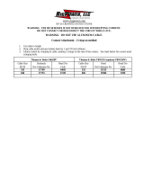
Tooling Index for 3M™ 3-Conductor In-line Splice Kits, 5750 Series, for Armored or Non-Armored Cables 1000 Volts or Less
Copper/Aluminum Connectors
CRIMPING TOOL/DIE SETS (NO. OF CRIMPS/END)
Connector dimensions
in Inches and
(millimeters)
Burndy Corporation Thomas & Betts Corporation
Square D Co.
Anderson Div.
ITT
Blackburn
Co.
Kearney-
Nat’l Inc.
Cable
Size
3M™
Scotchlok™
Aluminum
Connector
Number
Length Outside Dis. MD6 MY29 Y34A Y35, Y39, Y45*, Y46* Y1000** TBM5 TBM 8 TBM15 VC6-3, VC6-FT** OD58 Type 0
6 20001 1.620 (41,2) .344 (8,8) W161 (1) 6AWG (1) A6CAB (1) U6CABT (1) Universal (1) Grey (1) Grey (1) 29 (1) Universal (1) BY19 (3) J (3)
4 20002 1.880 (47,8) .468 (11,9) W162 (3) 4AWG (1) A4CAB (1) U4CABT (1) Universal (1) Green (2) Green (2) 37 (1) Universal (1) BY53 (3) P (3)
2 20003 2.000 (50,8) .531 (13,5) W163 (3) 2AWG (1) A2CAB (1) U2CABT (1) Universal (1) Pink (2) Pink (2) 42H (2) Universal (1) BY23 (3) 1/2 (3)
1 20004 2.000 (50,8) .531 (13,5) W163 (3) 1 AWG (1) A1CAR (1) U1CART (1) Universal (1) Gold (2) Gold (2) 45 (1) Universal (1) BY23 (3) 1/2 (3)
1/0 20005 2.120 (53,9) .640 (16,3) W241 (2) 1/0 (1) A25AR (1) U25ART (1) Universal (1) Tan (2) Tan (2) 50 (1) Universal (1) BY25 (3) 5/8-1 (3)
2/0 20006 2.310 (58,7) .687 (17,5) BG (4) 2/0 (1) A26AR (2) U26ART (2) Universal (1) Olive (2) Olive (2) 54H (2) Universal (2) BY31C (3) 5/8-1 (3)
3/0 20007 2.620 (86,6) .760 (19,3) W166 (4) 3/0 (1) A27AR (2) U27ART (2) Universal (1) Ruby (2) Ruby (2) 60 (2) Universal (2) ---- 737 (3)
4/0 20008 2.750 (86,9) .875 (22,2) W660 (4) 4/0 (2) A28AR (2) U28ART (2) Universal (1) --- White (4) 66 (4) Universal (2) BY35C (4) 840 (4)
250 20009 2.940 (74,7) .906 (23,0) W249 (3) --- A29AR (2) U29ART (2) Universal (1) --- Red (3) 71H (2) Universal (2) --- ---
300 20010 3.120 (79,3) 1.010 (25,7) --- --- A30AR (2) U30ART (2) --- --- Blue (4) 76 (1) --- --- ---
350 20011 3,380 (85,9) 1.105 (28,1) --- --- --- U31AR (2) --- --- Brown (4) 87H (2) --- --- ---
400 20012 3.750 (95,3) 1.187 (30,2) --- --- --- U32ART (4) --- --- --- 94H (1) --- --- ---
500 20014 3.880 (98,6) 1.320 (33,5) --- --- --- U34ART (4) --- --- --- 106H (3) --- --- ---
600 20016 4.120 (104,7) 1.438 (36,5) --- --- --- U36ART (4) --- --- --- 115H (2) --- --- ---
750 20019 4.620 (117,4) 1.510 (39,3) --- --- ---
Y39, Y45, Y46:
U39RT - 2 (4)
--- --- --- 125H (3) --- --- ---
*Y45 and Y46 accept all Y35 dies (“U” Series). For Y45 use PT515 adapter.
**Anderson VC6-3 and VC6-FT and Burndy Y1000 require no die set.
78-8126-9795-7 A
10 of 11

Tooling Index for 3M™ 3-Conductor In-line Splice Kits, 5750 Series, Non-Shielded, Armored or Non-Armored Cables 5 kV Rated
Copper Connectors
CRIMPING TOOL/DIE SETS (NO. OF CRIMPS/END)
Connector dimensions
in Inches and
(millimeters)
Burndy Corporation Thomas & Betts Corporation
Square D Co.
Anderson Div.
Cable
Size
3M™
Scotchlok™
Aluminum
Connector
Number
Length Outside Dis. MD6 MY29 Y34A Y35, Y39, Y45*, Y46* TBM5 TBM8 TBM15
V
C6-3, VC6-FT**
6 10001 1.75 (44,4) .290 (7,3) --- 6AWG (1) --- U5CRT (1) Blue (1) Blue (1) --- Universal (1)
4 10002 1.75 (44,4) .340 (8,6) W161 (1) 4AWG (1) A4CR (1) U4CRT (1) Grey (1) Grey (1) --- Universal (1)
2 10003 1.88 (47,7) .416 (10,6) W162 (2) 2AWG (1) A2CR (1) U2CRT (2) Brown (1) Brown (1) 33 (1) Universal (2)
1 10004 1.88 (47,7) .462 (11,7) --- 1AWG (1) A1CR (1) U1CRT (2) Green (1) Green (1) 37 (1) Universal (2)
1/0 10005 1.88 (47,7) .512 (13,0) W163 (2) 1/0 (1) A25R (1) U25RT (1) Pink (2) Pink (2) 42 (2) Universal (1)
2/0
10006
11006
2.00 (50,8)
3.13 (79,4)
,560 (14,2)
.560 (14,2)
W241 (2)
W241 (3)
2/0 (1)
2/0 (2)
A
26R (1)
A26R (2)
U26RT (2)
U26RT (3)
Black (2)
Black (3)
Black (2)
Black (3)
45 (1)
45 (2)
Universal (1)
Universal (2)
3/0
10007
11007
2.13 (54,0)
3.38 (79,4)
.617 (15,7)
.617 (15,7)
W243 (2)
W243 (3)
3/0 (1)
3/0 (2)
A
27R (1)
A27R (2)
U27RT (2)
U27RT (3)
Orange (2)
Orange (3)
Orange (2)
Orange (3)
50 (1)
50 (2)
Universal (1)
Universal (2)
4/0
10008
11008
2.13 (54,0)
3.38 (85,8)
.687 (17,4)
.687 (17,4)
BG (3)
BG (4)
4/0 (1)
4/0 (2)
A
28R (2)
A28R (3)
U28RT (2)
U28RT (3)
Purple (2)
Purple (3)
Purple (2)
Purple (3)
54H (2)
54H (3)
Universal (2)
Universal (3)
250
10009
11009
2.25 (57,2)
3.38 (85,8)
.750 (19,0)
.750 (19,0)
W166 (3)
W166 (4)
250 (1)
250 (2)
A
29R (2)
A29R (3)
U29RT (2)
U29RT (3)
Y
ellow (2)
Yellow (3)
Y
ellow (2)
Yellow (3)
62 (2)
62 (3)
Universal (2)
Universal (3)
300
10010
11010
2.25 (57,2)
4.13 (104,8)
.813 (20,7)
.813 (20,7)
--- ---
A
30R (2)
A30R (3)
U30RT (2)
U30RT (3)
---
White (2)
White (3)
66 (2)
66 (3)
Universal (2)
Universal (3)
350
10011
11011
2.38 (60,4)
4.13 (104,8)
.875 (22,2)
.875 (22,2)
--- ---
A31R (2)
A31R (3)
U31RT (2)
U31RT (3)
---
Red (3)
Red (4)
71H (3)
71H (4)
---
500
10014
11014
2.88 (73,1)
4.63 (117,5)
1.060 (27,0)
1.060 (27,0)
--- ---
A
34R (2)
A34R (4)
U34RT (2)
U34RT (3)
---
Brown (3)
Brown (4)
87H (3)
87H (4)
---
750
10019
11019
3.88 85,8)
5.88 (149,3)
1.299 (33,0)
1.299 (33,0)
--- --- ---
Y39, Y45, Y46: U39RT (3)
Y39, Y45, Y46: U39RT (5)
---- ---
106H (3)
106H (4)
---
*Y45 and Y46 accept all Y35 dies (“U” Series). For Y45 use PT515 adapter.
**Anderson VC6-3 and VC6-FT require no die set.
3M, Scotch, Scotchcast, Scotchlok, Super 33+, Three-M-Ite and Elek-Tro-Cut are trademarks of 3M Company.
Important Notice:
All statements, technical information, and recommendations related to 3M’s products are based on information believed to be reliable, but the accuracy or
completeness is not guaranteed. Before using this product, you must evaluate it and determine if it is suitable for your intended application. You assume all
risks and liability associated with such use. Any statements related to the product, which are not contained in 3M’s current publications, or any contrary
statements contained on your purchase order, shall have no force or effect unless expressly agreed upon, in writing, by an authorized officer of 3M.
Warranty; Limited Remedy; Limited Liability:
This product will be free from defects in material and manufacture at the time of purchase. 3M MAKES NO OTHER WARRANTIES INCLUDING, BUT NOT
LIMITED TO, ANY IMPLIED WARRANTY OF MERCHANTABILITY OR FITNESS FOR A PARTICULAR PURPOSE. If this product is defective within the
warranty period stated above, your exclusive remedy shall be, at 3M’s option, to replace or repair the 3M product or refund the purchase price of the 3M
product. Except where prohibited by law, 3M will not be liable for any indirect, special, incidental or consequential loss or damage arising from
this 3M product, regardless of the legal theory asserted.
3
Electrical Markets Division
6801 River Place Blvd.
Austin, TX 78726-9000
800.245.3573 Please Recycle. Printed in USA.
Fax 800.245.0329 © 3M 2011 All Rights Reserved.
www.3M.com/electrical 78-8126-9795-7 A
11 of 11
/