Page is loading ...

Crestron
®
DM-MD6X4/DM-MD6X6
DigitalMedia™ Distribution Center
Installation & Operation Guide

This document was prepared and written by the Technical Publications department at:
Crestron Electronics, Inc.
15 Volvo Drive
Rockleigh, NJ 07647
1-888-CRESTRON
The product warranty can be found at www.crestron.com/warranty
.
The specific patents that cover Crestron products can be found at patents.crestron.com
.
Certain Crestron products contain open source software. For more information, please visit www.crestron.com/opensource
.
Crestron, the Crestron logo, Auto-Locking, Crestron Toolbox, DigitalMedia, DigitalMedia 8G, DigitalMedia 8G+, DM, DM 8G+, QuickSwitch HD,
PROCISE, and SystemBuilder are either trademarks or registered trademarks of Crestron Electronics, Inc. in the United States and/or other countries.
Blu-ray Disc is either a trademark or a registered trademark of the Blu-ray Disc Association in the United States and/or other countries. Dolby and
Dolby Digital are either trademarks or registered trademarks of Dolby Laboratories in the United States and/or other countries. DTS, DTS HD, and
DTS HD Master Audio are either trademarks or registered trademarks of DTS, Inc. in the United States and/or other countries. HDBaseT and the
HDBT logo are either trademarks or registered trademarks of the HDBaseT Alliance in the United States and/or other countries. HDMI and the
HDMI logo are either trademarks or registered trademarks of HDMI Licensing, LLC in the United States and/or other countries. Windows is either a
trademark or a registered trademark of Microsoft Corporation in the United States and/or other countries. UL and the UL logo are either trademarks or
registered trademarks of Underwriters Laboratories, Inc., in the United States and/or other countries. Other trademarks, registered trademarks, and
trade names may be used in this document to refer to either the entities claiming the marks and names or their products. Crestron disclaims any
proprietary interest in the marks and names of others. Crestron is not responsible for errors in typography or photography.
©2017 Crestron Electronics, Inc.

Crestron DM-MD6X4/DM-MD6X6 DigitalMedia Distribution Center
Installation & Operation Guide – DOC. 7196B Contents • i
Contents
DigitalMedia™ Distribution Center: DM-MD6X4/DM-MD6X6 1
Introduction ............................................................................................................................... 1
Features and Functions ................................................................................................ 1
Applications................................................................................................................. 5
Internal Block Diagram ............................................................................................... 6
Specifications .............................................................................................................. 7
Physical Description .................................................................................................. 10
Setup ........................................................................................................................................ 16
Network Wiring ......................................................................................................... 16
Ethernet Setup ........................................................................................................... 16
Identity Code ............................................................................................................. 17
Installation ................................................................................................................. 17
Hardware Hookup ..................................................................................................... 19
Configuration and Status ......................................................................................................... 21
Accessing Installer Mode .......................................................................................... 21
Inputs ......................................................................................................................... 23
Outputs ...................................................................................................................... 24
Network ..................................................................................................................... 25
Control ....................................................................................................................... 29
Exiting Installer Mode ............................................................................................... 31
Programming Software ............................................................................................................ 32
Earliest Version Software Requirements for the PC ................................................. 32
Programming with SystemBuilder ............................................................................ 32
Programming with SIMPL Windows ........................................................................ 32
Uploading and Upgrading ........................................................................................................ 36
Establishing Communication ..................................................................................... 36
Programs and Firmware ............................................................................................ 37
Program Checks ........................................................................................................ 38
DMTool ..................................................................................................................... 38
Operation ................................................................................................................................. 39
Routing an Input Signal to Output(s) ........................................................................ 39
Disconnecting Routed Signal(s) ................................................................................ 40
Problem Solving ...................................................................................................................... 41
Troubleshooting ......................................................................................................... 41
Reference Documents ................................................................................................ 42
Further Inquiries ........................................................................................................ 42
Future Updates .......................................................................................................... 42


Crestron DM-MD6X4/DM-MD6X6 DigitalMedia Distribution Center
Installation & Operation Guide – DOC. 7196B DigitalMedia Distribution Center: DM-MD6X4/DM-MD6X6 • 1
• Provides a low-cost, high-performance multiroom HD AV signal
routing solution
• Distributes uncompressed digital video and audio over CAT5e
(or better) twisted-pair wire
1
• Affords a true one-wire solution using DigitalMedia 8G+ technology
• HDBaseT
®
Alliance Certified–Enables direct connection to other
HDBaseT certified equipment
• Features independently switchable HDBaseT or DM 8G+
®
outputs for
three (DM-MD6X4) or five (DM-MD6X6) remote displays
• Allows up to a 330-foot (100-meter) wire distance to each display
• Includes one HDMI
®
output for a local display or audio processor
• Provides inputs for six HDMI, DVI, or DisplayPort Multimode sources
2
• Handles video resolutions up to Full HD 1080p
• Handles computer resolutions up to WUXGA
• Handles 3D video and Deep Color
• Handles Dolby
®
TrueHD audio, DTS HD
®
audio, and uncompressed 7.1
linear PCM audio
• HDCP compliant
• QuickSwitch HD™ technology manages HDCP keys for fast, reliable
switching
DigitalMedia™ Distribution Center:
DM-MD6X4/DM-MD6X6
Introduction
The Crestron
®
DM-MD6X4 and DM-MD6X6 DigitalMedia™ distribution centers
distribute multiple high-definition sources to up to four rooms (DM-MD6X4) or up
to six rooms (DM-MD6X6) as part of a complete Crestron system. Featuring
DigitalMedia 8G+
®
technology, the DM-MD6X4 and DM-MD6X6 deliver
ultra high-bandwidth signal routing over CAT5e (or better) wiring
1
.
Features and Functions
(Continued on following page)
1. For DM 8G+ or HDBaseT wiring up to 330 feet (100 meters) between devices, use Crestron
DM-CBL-8G DigitalMedia 8G™ cable or generic CAT5e (or better) UTP or STP. Shielded cable and
connectors are recommended to safeguard against unpredictable environmental electrical noise that
may impact performance at resolutions above 1080p. For complete system design guidelines, refer to
the Crestron DigitalMedia Design Guide (Doc. 4546) at www.crestron.com/manuals
. All wire and
cables are sold separately.
2. HDMI requires an appropriate adapter or interface cable to accommodate a DVI or DisplayPort
Multimode signal. Crestron CBL-HD-DVI interface cables are sold separately.

DigitalMedia Distribution Center Crestron DM-MD6X4/DM-MD6X6
2 • DigitalMedia Distribution Center: DM-MD6X4/DM-MD6X6 Installation & Operation Guide – DOC. 7196B
• Auto-Locking
®
technology achieves rapid switching between disparate
sources
• Performs automatic AV signal format management via EDID
• Allows independent scaling for every display through select
DM
®
receivers
3
• Enables USB HID mouse and keyboard signal extension
• Expanded USB routing capabilities available using USB-EXT-DM USB
over Ethernet extenders
4
• Includes integrated Ethernet switch
• Private Network Mode–Requires only one IP address for the complete
DM system
• Provides Power over DM for PoDM compatible receivers
• Provides setup and diagnostics tools via front panel or software
• Includes built-in universal power supply
• Allows native Crestron system integration via Ethernet
• Standard component width or two-space rack mountable
Features and Functions
(Continued)
HD Matrix Switcher
The DM-MD6X4 and DM-MD6X6 provide six HDMI
®
inputs to handle HDTV
receivers, DVD or Blu-ray Disc
®
players, media servers, computers, and other HD
digital sources. Outputs include one HDMI and three (DM-MD6X4) or five
(DM-MD6X6) DigitalMedia ports, furnishing simple one-wire connectivity for a
local display or audio processor, and three (DM-MD6X4) or five (DM-MD6X6)
additional displays anywhere in the house. QuickSwitch HD™ matrix switching
allows any display to view any source at any time.
DigitalMedia 8G+
Crestron exclusive DM 8G+
®
technology affords the ultimate in simplicity,
providing a true one-wire interface for distributing high-definition video, audio, and
control signals to multiple displays throughout a residence or commercial structure.
Simply connect a DM 8G+ receiver
(sold separately) at each flat-panel display or
projector for a complete AV and control interface. Only one CAT5e (or better) wire
run to each receiver transports pure, uncompressed HD video, 7.1 surround sound
audio, 10/100 Ethernet, power, and control signals for a fully integrated media
system with minimal wiring. DM 8G+ allows for wire runs up to 330 feet (100
meters) using CAT5e (or better) or Crestron DigitalMedia 8G™ cable.
*
3. DM 8G+ receivers with built-in scaling include the DM-RMC-SCALER-C, DM-RMC-200-C,
DM-RMC-4K-SCALER-C, and DM-RMC-4K-SCALER-C-DSP. For the HDMI output, use the
HD-SCALER-HD-E or the HD-SCALER-VGA-E.
4. USB-EXT DM USB over Ethernet extender modules are sold separately. Refer to the USB-EXT-
DM spec sheet on the product webpage for more information.
* For DM 8G+ or HDBaseT wiring up to 330 feet (100 meters) between devices, use Crestron
DM-CBL-8G DigitalMedia 8G cable or generic CAT5e (or better) UTP or STP. Shielded cable and
connectors are recommended to safeguard against unpredictable environmental electrical noise that
may impact performance at resolutions above 1080p. For complete system design guidelines, refer to
the Crestron DigitalMedia Design Guide (Doc. 4546). All wire and cables are sold separately.

Crestron DM-MD6X4/DM-MD6X6 DigitalMedia Distribution Center
Installation & Operation Guide – DOC. 7196B DigitalMedia Distribution Center: DM-MD6X4/DM-MD6X6 • 3
HDBaseT
®
Alliance Certified
Crestron DigitalMedia 8G+ technology is designed using HDBaseT Alliance
specifications, ensuring interoperability with other HDBaseT certified products. Via
its DM 8G+ outputs, the DM-MD6X4 and DM-MD6X6 can be connected directly to
HDBaseT compliant display devices without requiring any DM
®
receivers.
Quickswitch HD
Handling high-definition digital media means handling HDCP (High-bandwidth
Digital Content Protection), which is the encryption scheme that content providers
use to protect their DVDs, Blu-ray Discs, and broadcast signals against unauthorized
copying. Viewing HDCP encrypted content requires the source device to
"authenticate" each display in the system and to issue it a key before the content can
be viewed. Ordinarily, this process causes a complete loss in signal for up to
15 seconds each time a new source or display is selected anywhere in the system.
Additionally, every source device has a limited number of keys available, so if too
many devices are connected, the source stops outputting a signal without warning.
Crestron Quickswitch HD solves this problem by managing keys for every
HDCP-compliant device in the system, maintaining continuous authentication for
each device to ensure fast, reliable routing of any source to any number of display
devices.
Auto-Locking
®
Technology
Crestron Auto-Locking technology enables high-speed signal switching by
instantaneously configuring every device in the signal path as soon as the signal
reaches the first device. Whether switching between sources or TV channels,
Auto-Locking significantly reduces the time it takes each device to sense the new
signal and to configure itself to handle the changes, virtually eliminating any
noticeable gap while switching.
EDID Format Management
The DM-MD6X4 and DM-MD6X6 manage the EDID (Extended Display
Identification Data) that modern digital devices use to communicate their
capabilities. Through the DM-MD6X4 and DM-MD6X6, the format and resolution
capabilities of each device can be assessed, allowing the installer to configure EDID
signals appropriately for the most desirable and predictable behavior.
A Scaler for Every Display
Scaling capability can be added to the DM-MD6X4 and DM-MD6X6 using select
DM 8G+ receivers (sold separately) with built-in HD and 4K scalers.
*
By placing an
independent high-performance scaler at every display device, DigitalMedia truly
delivers the most flexible and user-friendly solution for routing multiple disparate
sources to many different display devices. This “Distributed Scaler Approach”
ensures an optimal image on every screen no matter what sources are selected.
Distributed scaling allows a high-resolution computer source to be viewed on any
display in the building, and allows a high-definition 3D source to be viewed on lower
resolution 2D displays without compromising the original signal, such as letting a
home theater’s Full HD 1080p 3D image be shared with smaller, lesser displays in
other rooms.
* DM 8G+ receivers with built-in scaling include the DM-RMC-SCALER-C, DM-RMC-200-C,
DM-RMC-4K-SCALER-C, and DM-RMC-4K-SCALER-C-DSP. For the HDMI output, use the HD-
SCALER-HD-E or HD-SCALER-VGA-E.

DigitalMedia Distribution Center Crestron DM-MD6X4/DM-MD6X6
4 • DigitalMedia Distribution Center: DM-MD6X4/DM-MD6X6 Installation & Operation Guide – DOC. 7196B
Multi-Channel HD Audio Routing
The DM-MD6X4 and DM-MD6X6 allow for the routing of signals containing
multichannel surround sound audio, supporting high-bitrate formats such as
Dolby
®
TrueHD and DTS HD Master Audio™ technology, as well as uncompressed
linear PCM (pulse-code modulation).
Built-In Ethernet Switch
In addition to transporting digital video and audio, DigitalMedia can also extend
high-speed Ethernet to display devices that require a LAN connection. Ethernet is
also utilized internally by the Crestron control bus to manage all of the DM devices
in the system and provide display control in each room. Through the 10/100 Ethernet
port, the DM-MD6X4/DM-MD6X6 provides a single-point connection to a home
network or corporate LAN, requiring only one IP address for the complete DM
system, including all connected DM receivers.
USB Signal Routing
With built-in USB HID (Human Interface Device) signal routing, the
DM-MD6X4 and DM-MD6X6 can control a centralized computer or media server
using a mouse or keyboard in another room. The mouse and keyboard can be
connected to any DM 8G+ receiver (sold separately) that includes a USB HID port,
while the host computer is connected to the USB HID port on the rear panel of the
DM-MD6X4 or DM-MD6X6. Crestron also offers USB over Ethernet extenders
(USB-EXT-DM, sold separately), which may be used to enable the routing of
multiple USB devices of virtually any type that are managed seamlessly through the
DigitalMedia system.
*
CEC Embedded Device Control
The primary objective of every Crestron system is to enable precisely the control
desired for a seamless user experience. DigitalMedia provides an alternative to
conventional IR and RS-232 device control by harnessing the CEC (Consumer
Electronics Control) signal embedded in HDMI. Through a connection to a Crestron
control system, the DM-MD6X4 and DM-MD6X6 provides a gateway for
controlling many devices directly through their HDMI connections, which may
eliminate the need for any dedicated control wires or IR emitters.
Easy Setup
Setup for the DM-MD6X4 and DM-MD6X6 is designed to be quick and easy using
the device's front panel or Crestron Toolbox™ software, configuring inputs and
outputs automatically while letting the installer make intelligent design decisions
along the way. Out of the box, the DM-MD6X4 and DM-MD6X6 front panel
supports basic signal routing for testing and troubleshooting during installation. The
front panel label strips can be customized using Crestron Engraver software or
standard 3/8" tape labels, allowing for the clear designation of each input and output.
Inputs and outputs may also be designated by name through the software to appear
on the LCD display.
* USB-EXT DM USB over Ethernet extender modules are sold separately. Refer to the
USB-EXT-DM spec sheet on the product webpage for more information.

Crestron DM-MD6X4/DM-MD6X6 DigitalMedia Distribution Center
Installation & Operation Guide – DOC. 7196B DigitalMedia Distribution Center: DM-MD6X4/DM-MD6X6 • 5
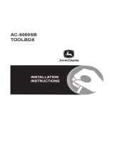
Applications
The diagram below shows a DM-MD6X6 in a typical application.
DM-MD6X6 in a Typical Application

DigitalMedia Distribution Center Crestron DM-MD6X4/DM-MD6X6
6 • DigitalMedia Distribution Center: DM-MD6X4/DM-MD6X6 Installation & Operation Guide – DOC. 7196B
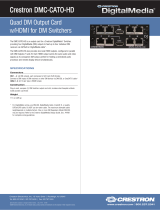
Internal Block Diagrams
The following diagrams represent the switching abilities of the DM-MD6X4 and
DM-MD6X6.
Internal Block Diagram of the DM-MD6X4
Internal Block Diagram of the DM-MD6X6

Crestron DM-MD6X4/DM-MD6X6 DigitalMedia Distribution Center
Installation & Operation Guide – DOC. 7196B DigitalMedia Distribution Center: DM-MD6X4/DM-MD6X6 • 7
Specifications
Specifications for the DM-MD6X4 and DM-MD6X6 are listed in the below table.
DM-MD6X4/DM-MD6X6 Specifications
SPECIFICATION DETAILS
Video
Switcher
6X4 (DM-MD6X4) or 6x6 (DM-MD6X6)
digital matrix switch, Crestron
QuickSwitch HD
Input Signal Types HDMI, DVI
1
, DisplayPort Multimode
1
Output Signal Types
HDMI, DVI
1
, DM 8G+ (DigitalMedia over
one CAT5e or better twisted pair copper
wire)
2
, HDBaseT
2
Formats
DM 8G+, HDBaseT, HDMI with Deep
Color and 3D; DVI; HDCP content
protection support
Input Resolutions
Progressive
640 x 480 @ 60 Hz
720 x 480 @ 60 Hz (480p)
720 x 576 @ 50 Hz (576p)
800 x 600 @ 60 Hz
848 x 480 @ 60 Hz
852 x 480 @ 60 Hz
854 x 480 @ 60 Hz
1024 x 768 @ 60 Hz
1024 x 852 @ 60 Hz
1024 x 1024 @ 60 Hz
1280 x 720 @ 50 Hz (720p50)
1280 x 720 @ 60 Hz (720p60)
1280 x 768 @ 60 Hz
1280 x 800 @ 60 Hz
1280 x 960 @ 60 Hz
1280 x 1024 @ 60 Hz
1360 x 768 @ 60 Hz
1365 x 1024 @ 60 Hz
1366 x 768 @ 60 Hz
1400 x 1050 @ 60 Hz
1440 x 900 @ 60 Hz
1600 x 900 @ 60 Hz
1600 x 1200 @ 60 Hz
1680 x 1050 @ 60 Hz
1920 x 1080 @ 24 Hz (1080p24)
1920 x 1080 @ 25 Hz (1080p25)
1920 x 1080 @ 50 Hz (1080p50)
1920 x 1080 @ 60 Hz (1080p60)
1920 x 1200 @ 60 Hz
2048 x 1080 @ 24 Hz
2048 x 1152 @ 60 Hz
plus any other resolution allowed by
HDMI up to 165 MHz pixel clock
Interlaced
720 x 480 @ 30 Hz (480i)
720 x 576 @ 25 Hz (576i)
1920 x 1080 @ 25 Hz (1080i25)
1920 x 1080 @ 30 Hz (1080i30)
plus any other resolution allowed by
HDMI up to 165 MHz pixel clock
(Continued on following page)

DigitalMedia Distribution Center Crestron DM-MD6X4/DM-MD6X6
8 • DigitalMedia Distribution Center: DM-MD6X4/DM-MD6X6 Installation & Operation Guide – DOC. 7196B
DM-MD6X4/DM-MD6X6 Specifications (Continued)
SPECIFICATION DETAILS
Video (Continued)
Output Resolutions Matched to inputs
Audio
Switcher
6x4 (DM-MD6X4) or 6x6 (DM-MD6X6)
digital matrix switch, audio-follow-video
Input Signal Types HDMI, DisplayPort Multimode
1
Output Signal Types HDMI, DM 8G+. HDBaseT
Formats
Dolby Digital
®
audio, Dolby Digital EX,
Dolby Digital Plus, Dolby TrueHD,
DTS
®
audio, DTS ES, DTS 96/24, DTS
HD High Res, DTS HD Master Audio, up
to 8ch PCM
Communications
DigitalMedia
DM 8G+, HDCP
3
, EDID
3
, CEC
3
, PoDM,
Ethernet
Ethernet
10/100 Mbps, auto-switching,
auto-negotiating, auto-discovery, full/half
duplex, DHCP, Private Network Mode
HDBaseT HDCP
3
, EDID
3
, PoH, Ethernet
HDMI HDCP
3
, EDID
3
, CEC
3
USB
Supports signal extension and routing of
USB HID class devices, expandable to
support almost any USB 1.1 or 2.0 device
using Crestron USB-EXT-DM USB over
Ethernet extenders
4
; USB device port for
computer console (setup)
Power Requirements
Main Power
Power over DM (PoDM)
2 Amps @ 100-240 Volts AC, 50/60 Hz
PoDM PSE (Power Sourcing Equipment),
each DM 8G+ port supplies up to 15.4
Watts (Class 0–3) to one PoDM Powered
Device
Power over HDBaseT (PoH)
PoH PSE (Power Sourcing Equipment),
each DM 8G+ port supplies up to 15.4
Watts (Class 0–3) to one PoDM Powered
Device
Environmental
Temperature 32 ºF to 104 ºF (0 ºC to 40 ºC)
Humidity 10% to 90% RH (non-condensing)
Heat Dissipation 310 BTU/hr
(Continued on following page)

Crestron DM-MD6X4/DM-MD6X6 DigitalMedia Distribution Center
Installation & Operation Guide – DOC. 7196B DigitalMedia Distribution Center: DM-MD6X4/DM-MD6X6 • 9
DM-MD6X4/DM-MD6X6 Specifications (Continued)
SPECIFICATION DETAILS
Enclosure
Chassis
Metal with black finish, vented sides,
fan cooled
Faceplate
Metal, black finish with polycarbonate
label overlay
Mounting
Freestanding or 2U 19-inch rack
mountable (adhesive feet and rack ears
included)
Dimensions
Height 3.47 in (89 mm) without feet
Width
17.03 in (433 mm) without ears,
19.00 in (483 mm) with ears
Depth 13.38 in (340 mm)
Weight 12.0 lb (5.5 kg)
Available Accessories
CBL Series Crestron Certified Interface Cables
DM-8G-CONN DigitalMedia 8G Cable Connectors
DM-8G-CONN-WG
DigitalMedia 8G Cable Connectors with
Wire Guide
DM-8G-CRIMP Crimping Tool for DM-8G-CONN
DM-8G-CRIMP-WG Crimping Tool for DM-8G-CONN-WG
DM-CBL-8G DigitalMedia 8G Cable
DM-RMC-200-C
DigitalMedia 8G+ Receiver & Room
Controller 200
DM-RMC-4K-100-C
4K DigitalMedia 8G+ Receiver & Room
Controller 100
DM-RMC-4K-SCALER-C
4K DigitalMedia 8G+ Receiver & Room
Controller with Scaler
DM-RMC-4K-SCALER-C-DSP
4K DigitalMedia 8G+ Receiver & Room
Controller with Scaler
DM-RMC-SCALER-C
DigitalMedia 8G+ Receiver & Room
Controller with Scaler & Downmixing
HD-SCALER-HD-E
High-Definition Video Scaler, HDMI In
and HDMI Out
HD-SCALER-VGA-E
High Definition Video Scaler, VGA In,
HDMI Out
MP-WP(I) Series
Media Presentation Wall Plates (U.S. and
International Versions)
USB-EXT DM USB over Ethernet Extender with Routing
1. HDMI requires an appropriate adapter or interface cable to accommodate a DVI or DisplayPort
Multimode signal. Crestron CBL-HD-DVI interface cables are sold separately.
2. For DM 8G+ or HDBaseT wiring up to 330 feet (100 meters) between devices, use Crestron
DM-CBL-8G DigitalMedia 8G cable or generic CAT5e (or better) UTP or STP. Shielded cable and
connectors are recommended to safeguard against unpredictable environmental electrical noise that
may impact performance at resolutions above 1080p. For complete system design guidelines, refer to
the Crestron DigitalMedia Design Guide (Doc. 4546). All wire and cables are sold separately.
3. The DM-RM6X4 and DM-RM6X6 support management of HDCP and EDID; the devices also
support management of CEC between the connected HDMI devices and a control system.
4. USB-EXT DM USB over Ethernet extender modules are sold separately. Refer to the USB-EXT-DM
spec sheet on the product webpage for more information.

DigitalMedia Distribution Center Crestron DM-MD6X4/DM-MD6X6
10 • DigitalMedia Distribution Center: DM-MD6X4/DM-MD6X6 Installation & Operation Guide – DOC. 7196B
Physical Description
This section provides information on the connections, controls, and indicators
available on the DM-MD6X4 and DM-MD6X6.
DM-MD6X4 Physical Views (Front and Rear)
DM-MD6X6 Physical Views (Front and Rear)

Crestron DM-MD6X4/DM-MD6X6 DigitalMedia Distribution Center
Installation & Operation Guide – DOC. 7196B DigitalMedia Distribution Center: DM-MD6X4/DM-MD6X6 • 11
DM-MD6X4/DM-MD6X6 Overall Dimensions (Top View)
17.03 in
(433 mm)
13.00 in
(331 mm)
16.79 in
(427 mm)
0.35 in
(9 mm)
DM-MD6X4/DM-MD6X6 Overall Dimensions (Front View, DM-MD6X6 Shown)
19.00 in
(483 mm)
18.31 in
(466 mm)
3.00 in
(77 mm)
3.47 in
(89 mm)
0.24 in
(7 mm)

DigitalMedia Distribution Center Crestron DM-MD6X4/DM-MD6X6
12 • DigitalMedia Distribution Center: DM-MD6X4/DM-MD6X6 Installation & Operation Guide – DOC. 7196B
DM-MD6X4 Connectors, Controls, and Indicators (Front and Rear Views)
1
54
3
2 6
7 8
9 10 11
12
14
15
13
DM-MD6X6 Connectors, Controls, and Indicators (Front and Rear Views)
9 10
11
12
14
15
13
1
543
2 6
7 8

Crestron DM-MD6X4/DM-MD6X6 DigitalMedia Distribution Center
Installation & Operation Guide – DOC. 7196B DigitalMedia Distribution Center: DM-MD6X4/DM-MD6X6 • 13
Connectors, Controls, and Indicators
# CONNECTORS,
CONTROLS &
INDICATORS
DESCRIPTION
1 HW-R Button
(1) Recessed miniature push button for
hardware reset
2
COMPUTER
Pin
4
Pin
1
Pin 3
Pin 2
(1) USB Type B female;
USB computer console port (setup only)
(6 foot [~1.8 meters] cable included)
PIN DESCRIPTION
1 +5 VDC
2
Data -
3
Data +
4
Ground
3
Liquid Crystal Display
(LCD)
(1) 16-bit TFT active matrix color LCD;
2 inch (52 mm) diagonal;
220 x 176 pixel resolution;
Displays setup menus, EDID and HDCP
details for source and destination
devices, audio/video signal information,
and other details;
Allows custom naming of inputs and
outputs
4
Navigation Pad
(1) 5-way navigation pad for menu
navigation and parameter adjustment:
Up, Down, Left, and Right navigation
buttons;
Select button: Executes highlighted
menu item or value
5 HOME Button
(1) Push button, returns to the home
screen
6 BACK Button
(1) Push button, steps menu back one
menu level
7
INPUT Buttons and LEDs,
1–6
(6) Push buttons and green LEDs, select
input for routing
8
OUTPUT Buttons and
LEDs, 1–4/1–6
DM-MD6X4 (4) or DM-MD6X6 (6) push
buttons and green LEDs, select output
destination(s)
9
INPUT
HDMI 1 – HDMI 6
(6) 19-pin Type A HDMI female,
digital video/audio inputs;
Signal Types: HDMI, DVI, or DisplayPort
Multimode
1
10
OUTPUT
HDMI 1
(1) 19-pin Type A HDMI female,
digital video/audio output;
Signal Types: HDMI, DVI
1
(Continued on following page)

DigitalMedia Distribution Center Crestron DM-MD6X4/DM-MD6X6
14 • DigitalMedia Distribution Center: DM-MD6X4/DM-MD6X6 Installation & Operation Guide – DOC. 7196B
Connectors, Controls, and Indicators (Continued)
# CONNECTORS,
CONTROLS &
INDICATORS
DESCRIPTION
11
OUTPUT
DM2 – DM4/DM2 – DM6
2, 3
Green
LED
Amber
LED
Pin 8
Pin 1
DM-MD6X4 (3) or DM-MD6X6 (5)
8-pin RJ-45 female, shielded, with two
LED indicators;
DM 8G+ outputs, HDBaseT compliant
PoDM and PoH PSE (Power Sourcing
Equipment) ports
4
Connects to DM 8G+ inputs of DM
receivers/room controllers or other DM
devices, or to an HDBaseT device, via
CAT5e (or better) or Crestron DM-CBL-
8G cable.
5
Green LED indicates DM link
status; Solid amber LED indicates HDCP
video; Blinking amber LED indicates non-
HDCP video
12
USB HID
Pin 2
Pin 3
Pin 1
Pin 4
(1) USB Type B female;
Supports signal extension and routing of
USB HID class devices, expandable to
support almost any USB 1.1 or 2.0
device using Crestron USB-EXT-DM
USB over Ethernet extenders
6
PIN DESCRIPTION
1
+5 VDC
2
Data -
3
Data +
4
Ground
13
LAN
2
Green
LED
Amber
LED
Pin 8
Pin 1
(1) 8-pin RJ-45 female, shielded, with
two LED indicators;
10BASE-T/100BASE-TX Ethernet port,
Green LED indicates Ethernet link status;
Amber LED indicates Ethernet activity
PIN
SIGNAL
PIN
SIGNAL
1
TX +
5
N/C
2
TX -
6
RX -
3
RX +
7
N/C
4
N/C
8
N/C
14
G
(1) 6-32 screw, chassis ground lug
15
100–240V ~ 2.0A MAX
50/60 Hz
(1) IEC C14 male chassis plug, main
power input:
Mates with removable power cord
(included)
1. HDMI requires an appropriate adapter or interface cable to accommodate a DVI or DisplayPort
Multimode signal. Crestron CBL-HD-DVI interface cables are sold separately.
2. To determine which is pin 1 on the cable, hold the cable so the end of the eight pin modular jack is
facing away from you, with the clip down and copper side up. Pin 1 is on the far left.
3. A DM output port consists of an RJ-45 connector. Refer to the table on the following page for the
connector pinouts.

Crestron DM-MD6X4/DM-MD6X6 DigitalMedia Distribution Center
Installation & Operation Guide – DOC. 7196B DigitalMedia Distribution Center: DM-MD6X4/DM-MD6X6 • 15
DM Output Connector Pinouts
1 8
PIN # WIRE COLOR PIN # WIRE COLOR
1 Orange/White 5 Blue/White
2 Orange 6 Green
3 Green/White 7 Brown/White
4 Blue 8 Brown
4. Any wiring that is connected to a PoDM or PoH PSH port is for intra-building use only and should
not be connected to a line that runs outside of the building in which the PSE is located.
5. For DM 8G+ or HDBaseT wiring up to 330 feet (100 meters) between devices, use Crestron
DM-CBL-8G DigitalMedia 8G cable or generic CAT5e (or better) UTP or STP. Shielded cable and
connectors are recommended to safeguard against unpredictable environmental electrical noise that
may impact performance at resolutions above 1080p. For complete system design guidelines, refer to
the Crestron DigitalMedia Design Guide (Doc. 4546). All wire and cables are sold separately.
6. USB-EXT DM USB over Ethernet extender modules are sold separately. Refer to the
USB-EXT-DM spec sheet on the product webpage for more information.

DigitalMedia Distribution Center Crestron DM-MD6X4/DM-MD6X6
16 • DigitalMedia Distribution Center: DM-MD6X4/DM-MD6X6 Installation & Operation Guide – DOC. 7196B
Setup
Network Wiring
When wiring the DM network, consider the following:
• Use Crestron Certified Wire.
• Use Crestron power supplies for Crestron equipment.
CAUTION: Failure to use Crestron power supplies could cause equipment
damage or void the Crestron warranty.
• Provide sufficient power to the system.
• For DM 8G+ or HDBaseT wiring up to 330 feet (100 meters) between
devices, use Crestron DM-CBL-8G DigitalMedia 8G cable or generic
CAT5e (or better) UTP or STP. Shielded cable and connectors are
recommended to safeguard against unpredictable environmental electrical
noise that may impact performance at resolutions above 1080p. For
complete system design guidelines, refer to the Crestron DigitalMedia
Design Guide (Doc. 4546). All wire and cables are sold separately.
The DM-MD6X4 and DM-MD6X6 also use high-speed Ethernet for
communications between the device and a control system, computer, media server
and other IP-based devices. For information related to Ethernet connectivity using
DigitalMedia devices, refer to the IP Considerations Guidelines for the IT
Professional Design Guide (Doc. 4579) at www.crestron.com/manuals.
Ethernet Setup
The DM-MD6X4 and DM-MD6X6 are designed to control the Ethernet settings of
DM endpoints in order to reduce the amount of IP configuration necessary and make
the DM endpoints swappable without reconfiguration. For the DM-MD6X4 and
DM-MD6X6, DM endpoints consist of DM 8G+ receivers/room controllers such as
the DM-RMC-SCALER-C, DM-RMC-200-C, DM-RMC-4K-SCALER-C, and
DM-RMC-4K-SCALER-C-DSP.
IP Configuration
The DM-MD6X4 and DM-MD6X6 can operate in DHCP or Static IP Address mode.
The DM-MD6X4 and DM-MD6X6 also control the IP addressing information of
DM 8G+ receivers/room controllers. When the DM-MD6X4 and DM-MD6X6
operate in DHCP mode, the DM 8G+ receivers/room controllers also operate in
DHCP mode. When the DM-MD6X4 and DM-MD6X6 operate in Static IP Address
mode, the DM 8G+ receivers/room controllers receive a static IP configuration
equivalent to the DM-MD6X4 or DM-MD6X6 IP address plus their slot number.
This configuration is sent when the DM-MD6X4 or DM-MD6X6 starts up. Refer to
the following table for information about static IP address configuration of DM 8G+
receivers/room controllers.
/