Page is loading ...
Visit our website at
www.MillerWelds.com
Processes
Description
Stick (SMAW) Welding
MIG (GMAW) Welding
Secondary Contactor
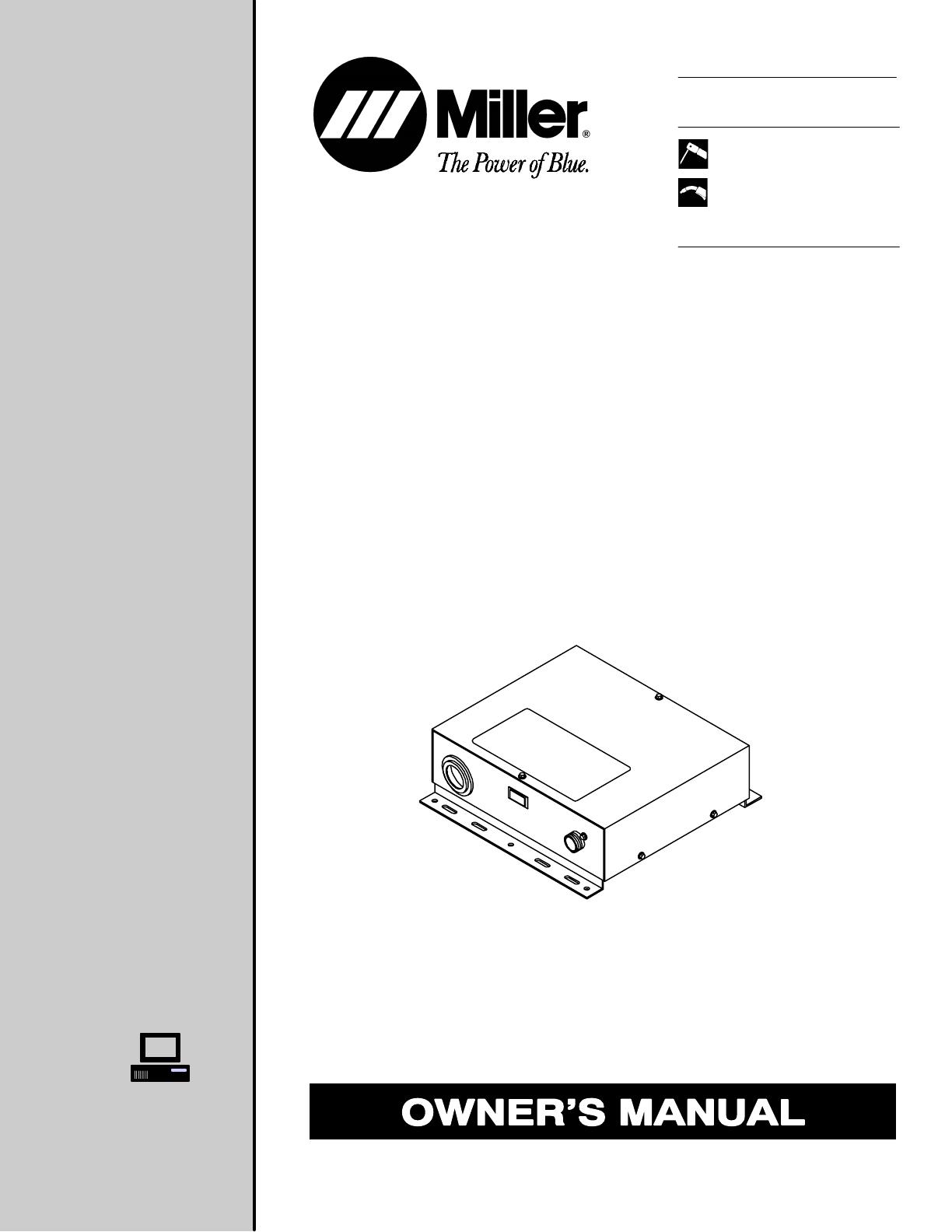
OM-534 109 946B
June 1996
Secondary Contactor

Miller Electric manufactures a full line
of welders and welding related equipment.
For information on other quality Miller
products, contact your local Miller distributor
to receive the latest full line catalog or
individual catalog sheets. To locate your nearest
distributor or service agency call 1-800-4-A-Miller,
or visit us at www.MillerWelds.com on the web.
Thank you and congratulations on choosing Miller. Now
you can get the job done and get it done right. We know
you don’t have time to do it any other way.
That’s why when Niels Miller first started building arc
welders in 1929, he made sure his products offered
long-lasting value and superior quality. Like you, his
customers couldn’t afford anything less. Miller products
had to be more than the best they could be. They had to
be the best you could buy.
Today, the people that build and sell Miller products continue the
tradition. They’re just as committed to providing equipment and service
that meets the high standards of quality and value established in 1929.
This Owner’s Manual is designed to help you get the most out of your
Miller products. Please take time to read the Safety precautions. They will
help you protect yourself against potential hazards on the worksite. We’ve
made installation and operation quick and easy.
With Miller you can count on years of reliable
service with proper maintenance. And if for
some reason the unit needs repair, there’s a
Troubleshooting section that will help you
figure out what the problem is. The parts list
will then help you to decide which exact part
you may need to fix the problem. Warranty and
service information for your particular model
are also provided.
Miller is the first welding
equipment manufacturer in
the U.S.A. to be registered to
the ISO 9001 Quality System
Standard.
Working as hard as you do
– every power source from
Miller is backed by the most
hassle-free warranty in the
business.
From Miller to You
Miller offers a Technical
Manual which provides
more detailed service and
parts information for your
unit. To obtain a Technical
Manual, contact your local
distributor. Your distributor
can also supply you with
Welding Process Manuals
such as SMAW, GTAW,
GMAW, and GMAW-P.

The following terms are
used interchangeably
throughout this manual:
Stick = SMAW
TABLE OF CONTENTS
SECTION 1 – SAFETY PRECAUTIONS - READ BEFORE USING 1. . . . . . . . . . . . . . . . . . . . . . . . . . . .
1-1. Symbol Usage 1. . . . . . . . . . . . . . . . . . . . . . . . . . . . . . . . . . . . . . . . . . . . . . . . . . . . . . . . . . . . . . . .
1-2. Arc Welding Hazards 1. . . . . . . . . . . . . . . . . . . . . . . . . . . . . . . . . . . . . . . . . . . . . . . . . . . . . . . . . .
1-3. Additional Symbols For Installation, Operation, And Maintenance 3. . . . . . . . . . . . . . . . . . . . .
1-4. Principal Safety Standards 3. . . . . . . . . . . . . . . . . . . . . . . . . . . . . . . . . . . . . . . . . . . . . . . . . . . . .
1-5. EMF Information 4. . . . . . . . . . . . . . . . . . . . . . . . . . . . . . . . . . . . . . . . . . . . . . . . . . . . . . . . . . . . . .
SECTION 2 – SPECIFICATIONS 5. . . . . . . . . . . . . . . . . . . . . . . . . . . . . . . . . . . . . . . . . . . . . . . . . . . . . . . . .
2-1. Secondary Contactor 5. . . . . . . . . . . . . . . . . . . . . . . . . . . . . . . . . . . . . . . . . . . . . . . . . . . . . . . . . .
2-2. Duty Cycle 5. . . . . . . . . . . . . . . . . . . . . . . . . . . . . . . . . . . . . . . . . . . . . . . . . . . . . . . . . . . . . . . . . . .
SECTION 3 – INSTALLATION 6. . . . . . . . . . . . . . . . . . . . . . . . . . . . . . . . . . . . . . . . . . . . . . . . . . . . . . . . . . .
3-1. Overall Dimensions And Installation 6. . . . . . . . . . . . . . . . . . . . . . . . . . . . . . . . . . . . . . . . . . . . . .
3-2. Making Internal Weld Cable Connections 7. . . . . . . . . . . . . . . . . . . . . . . . . . . . . . . . . . . . . . . . .
3-3. Trigger Hold Jumper Link 8. . . . . . . . . . . . . . . . . . . . . . . . . . . . . . . . . . . . . . . . . . . . . . . . . . . . . . .
3-4. SMAW Connections 9. . . . . . . . . . . . . . . . . . . . . . . . . . . . . . . . . . . . . . . . . . . . . . . . . . . . . . . . . . .
3-5. GMAW Connections 10. . . . . . . . . . . . . . . . . . . . . . . . . . . . . . . . . . . . . . . . . . . . . . . . . . . . . . . . . . .
3-6. Connecting Input Power 11. . . . . . . . . . . . . . . . . . . . . . . . . . . . . . . . . . . . . . . . . . . . . . . . . . . . . . . .
SECTION 4 – OPERATION 12. . . . . . . . . . . . . . . . . . . . . . . . . . . . . . . . . . . . . . . . . . . . . . . . . . . . . . . . . . . . .
4-1. Contactor Operation 12. . . . . . . . . . . . . . . . . . . . . . . . . . . . . . . . . . . . . . . . . . . . . . . . . . . . . . . . . . .
SECTION 5 – MAINTENANCE & TROUBLESHOOTING 12. . . . . . . . . . . . . . . . . . . . . . . . . . . . . . . . . . . .
5-1. Routine Maintenance 12. . . . . . . . . . . . . . . . . . . . . . . . . . . . . . . . . . . . . . . . . . . . . . . . . . . . . . . . . .
5-2. Overload Protection: Fuse F1 13. . . . . . . . . . . . . . . . . . . . . . . . . . . . . . . . . . . . . . . . . . . . . . . . . . .
5-3. Troubleshooting 13. . . . . . . . . . . . . . . . . . . . . . . . . . . . . . . . . . . . . . . . . . . . . . . . . . . . . . . . . . . . . .
SECTION 6 – ELECTRICAL DIAGRAM 14. . . . . . . . . . . . . . . . . . . . . . . . . . . . . . . . . . . . . . . . . . . . . . . . . . .
SECTION 7 – PARTS LIST 16. . . . . . . . . . . . . . . . . . . . . . . . . . . . . . . . . . . . . . . . . . . . . . . . . . . . . . . . . . . . . .
WARRANTY

OM-534 Page 1
SECTION 1 – SAFETY PRECAUTIONS - READ BEFORE USING
som _nd_5/97
1-1. Symbol Usage
Means Warning! Watch Out! There are possible hazards
with this procedure! The possible hazards are shown in
the adjoining symbols.
Y Marks a special safety message.
. Means “Note”; not safety related.
This group of symbols means Warning! Watch Out! possible
ELECTRIC SHOCK, MOVING PARTS, and HOT PARTS hazards.
Consult symbols and related instructions below for necessary actions
to avoid the hazards.
1-2. Arc Welding Hazards
Y The symbols shown below are used throughout this manual to
call attention to and identify possible hazards. When you see
the symbol, watch out, and follow the related instructions to
avoid the hazard. The safety information given below is only
a summary of the more complete safety information found in
the Safety Standards listed in Section 1-4. Read and follow all
Safety Standards.
Y Only qualified persons should install, operate, maintain, and
repair this unit.
Y During operation, keep everybody, especially children, away.
ELECTRIC SHOCK can kill.
Touching live electrical parts can cause fatal shocks
or severe burns. The electrode and work circuit is
electrically live whenever the output is on. The input
power circuit and machine internal circuits are also
live when power is on. In semiautomatic or automatic wire welding, the
wire, wire reel, drive roll housing, and all metal parts touching the
welding wire are electrically live. Incorrectly installed or improperly
grounded equipment is a hazard.
D Do not touch live electrical parts.
D Wear dry, hole-free insulating gloves and body protection.
D Insulate yourself from work and ground using dry insulating mats
or covers big enough to prevent any physical contact with the work
or ground.
D Do not use AC output in damp areas, if movement is confined, or if
there is a danger of falling.
D Use AC output ONLY if required for the welding process.
D If AC output is required, use remote output control if present on
unit.
D Disconnect input power or stop engine before installing or
servicing this equipment. Lockout/tagout input power according to
OSHA 29 CFR 1910.147 (see Safety Standards).
D Properly install and ground this equipment according to its
Owner’s Manual and national, state, and local codes.
D Always verify the supply ground – check and be sure that input
power cord ground wire is properly connected to ground terminal in
disconnect box or that cord plug is connected to a properly
grounded receptacle outlet.
D When making input connections, attach proper grounding conduc-
tor first – double-check connections.
D Frequently inspect input power cord for damage or bare wiring –
replace cord immediately if damaged – bare wiring can kill.
D Turn off all equipment when not in use.
D Do not use worn, damaged, undersized, or poorly spliced cables.
D Do not drape cables over your body.
D If earth grounding of the workpiece is required, ground it directly
with a separate cable – do not use work clamp or work cable.
D Do not touch electrode if you are in contact with the work, ground,
or another electrode from a different machine.
D Use only well-maintained equipment. Repair or replace damaged
parts at once. Maintain unit according to manual.
D Wear a safety harness if working above floor level.
D Keep all panels and covers securely in place.
D Clamp work cable with good metal-to-metal contact to workpiece
or worktable as near the weld as practical.
D Insulate work clamp when not connected to workpiece to prevent
contact with any metal object.
D Do not connect more than one electrode or work cable to any
single weld output terminal.
SIGNIFICANT DC VOLTAGE exists after removal of
input power on inverters.
D Turn Off inverter, disconnect input power, and discharge input
capacitors according to instructions in Maintenance Section
before touching any parts.
Welding produces fumes and gases. Breathing
these fumes and gases can be hazardous to your
health.
FUMES AND GASES can be hazardous.
D Keep your head out of the fumes. Do not breathe the fumes.
D If inside, ventilate the area and/or use exhaust at the arc to remove
welding fumes and gases.
D If ventilation is poor, use an approved air-supplied respirator.
D Read the Material Safety Data Sheets (MSDSs) and the
manufacturer’s instructions for metals, consumables, coatings,
cleaners, and degreasers.
D Work in a confined space only if it is well ventilated, or while
wearing an air-supplied respirator. Always have a trained watch-
person nearby. Welding fumes and gases can displace air and
lower the oxygen level causing injury or death. Be sure the breath-
ing air is safe.
D Do not weld in locations near degreasing, cleaning, or spraying op-
erations. The heat and rays of the arc can react with vapors to form
highly toxic and irritating gases.
D Do not weld on coated metals, such as galvanized, lead, or
cadmium plated steel, unless the coating is removed from the weld
area, the area is well ventilated, and if necessary, while wearing an
air-supplied respirator. The coatings and any metals containing
these elements can give off toxic fumes if welded.

OM-534 Page 2
Arc rays from the welding process produce intense
visible and invisible (ultraviolet and infrared) rays
that can burn eyes and skin. Sparks fly off from the
weld.
ARC RAYS can burn eyes and skin.
D Wear a welding helmet fitted with a proper shade of filter to protect
your face and eyes when welding or watching (see ANSI Z49.1
and Z87.1 listed in Safety Standards).
D Wear approved safety glasses with side shields under your
helmet.
D Use protective screens or barriers to protect others from flash and
glare; warn others not to watch the arc.
D Wear protective clothing made from durable, flame-resistant mate-
rial (leather and wool) and foot protection.
Welding on closed containers, such as tanks,
drums, or pipes, can cause them to blow up. Sparks
can fly off from the welding arc. The flying sparks, hot
workpiece, and hot equipment can cause fires and
burns. Accidental contact of electrode to metal objects can cause
sparks, explosion, overheating, or fire. Check and be sure the area is
safe before doing any welding.
WELDING can cause fire or explosion.
D Protect yourself and others from flying sparks and hot metal.
D Do not weld where flying sparks can strike flammable material.
D Remove all flammables within 35 ft (10.7 m) of the welding arc. If
this is not possible, tightly cover them with approved covers.
D Be alert that welding sparks and hot materials from welding can
easily go through small cracks and openings to adjacent areas.
D Watch for fire, and keep a fire extinguisher nearby.
D Be aware that welding on a ceiling, floor, bulkhead, or partition can
cause fire on the hidden side.
D Do not weld on closed containers such as tanks, drums, or pipes,
unless they are properly prepared according to AWS F4.1 (see
Safety Standards).
D Connect work cable to the work as close to the welding area as
practical to prevent welding current from traveling long, possibly
unknown paths and causing electric shock and fire hazards.
D Do not use welder to thaw frozen pipes.
D Remove stick electrode from holder or cut off welding wire at
contact tip when not in use.
D Wear oil-free protective garments such as leather gloves, heavy
shirt, cuffless trousers, high shoes, and a cap.
D Remove any combustibles, such as a butane lighter or matches,
from your person before doing any welding.
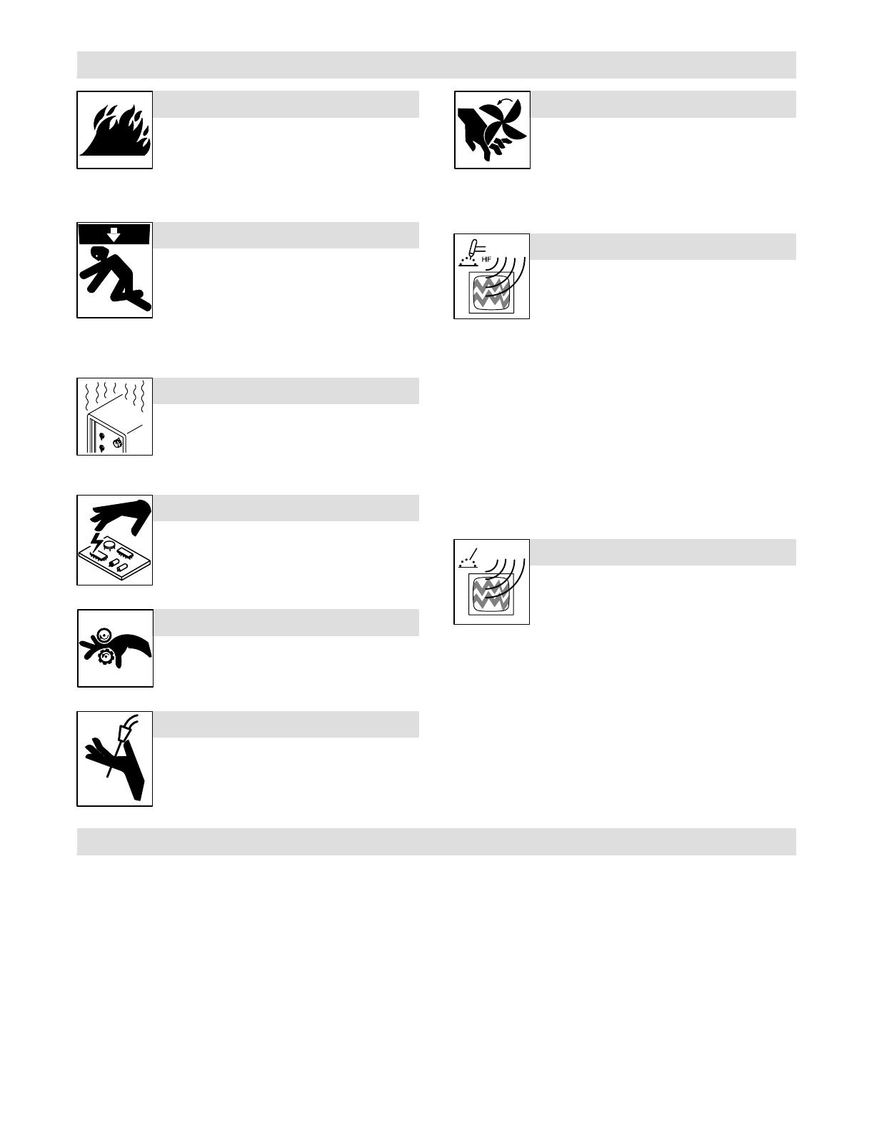
FLYING METAL can injure eyes.
D Welding, chipping, wire brushing, and grinding
cause sparks and flying metal. As welds cool,
they can throw off slag.
D Wear approved safety glasses with side
shields even under your welding helmet.
BUILDUP OF GAS can injure or kill.
D Shut off shielding gas supply when not in use.
D Always ventilate confined spaces or use
approved air-supplied respirator.
HOT PARTS can cause severe burns.
D Do not touch hot parts bare handed.
D Allow cooling period before working on gun or
torch.
MAGNETIC FIELDS can affect pacemakers.
D Pacemaker wearers keep away.
D Wearers should consult their doctor before
going near arc welding, gouging, or spot
welding operations.
NOISE can damage hearing.
Noise from some processes or equipment can
damage hearing.
D Wear approved ear protection if noise level is
high.
Shielding gas cylinders contain gas under high
pressure. If damaged, a cylinder can explode. Since
gas cylinders are normally part of the welding
process, be sure to treat them carefully.
CYLINDERS can explode if damaged.
D Protect compressed gas cylinders from excessive heat, mechani-
cal shocks, slag, open flames, sparks, and arcs.
D Install cylinders in an upright position by securing to a stationary
support or cylinder rack to prevent falling or tipping.
D Keep cylinders away from any welding or other electrical circuits.
D Never drape a welding torch over a gas cylinder.
D Never allow a welding electrode to touch any cylinder.
D Never weld on a pressurized cylinder – explosion will result.
D Use only correct shielding gas cylinders, regulators, hoses, and fit-
tings designed for the specific application; maintain them and
associated parts in good condition.
D Turn face away from valve outlet when opening cylinder valve.
D Keep protective cap in place over valve except when cylinder is in
use or connected for use.
D Read and follow instructions on compressed gas cylinders,
associated equipment, and CGA publication P-1 listed in Safety
Standards.
OM-534 Page 3
1-3. Additional Symbols For Installation, Operation, And Maintenance
FIRE OR EXPLOSION hazard.
D Do not install or place unit on, over, or near
combustible surfaces.
D Do not install unit near flammables.
D Do not overload building wiring – be sure power supply system is
properly sized, rated, and protected to handle this unit.
FALLING UNIT can cause injury.
D Use lifting eye to lift unit only, NOT running
gear, gas cylinders, or any other accessories.
D Use equipment of adequate capacity to lift and
support unit.
D If using lift forks to move unit, be sure forks are
long enough to extend beyond opposite side of
unit.
OVERUSE can cause OVERHEATING
D Allow cooling period; follow rated duty cycle.
D Reduce current or reduce duty cycle before
starting to weld again.
D Do not block or filter airflow to unit.
STATIC (ESD) can damage PC boards.
D Put on grounded wrist strap BEFORE handling
boards or parts.
D Use proper static-proof bags and boxes to
store, move, or ship PC boards.
MOVING PARTS can cause injury.
D Keep away from moving parts.
D Keep away from pinch points such as drive
rolls.
WELDING WIRE can cause injury.
D Do not press gun trigger until instructed to do
so.
D Do not point gun toward any part of the body,
other people, or any metal when threading
welding wire.
MOVING PARTS can cause injury.
D Keep away from moving parts such as fans.
D Keep all doors, panels, covers, and guards
closed and securely in place.
H.F. RADIATION can cause interference.
D High-frequency (H.F.) can interfere with radio
navigation, safety services, computers, and
communications equipment.
D Have only qualified persons familiar with
electronic equipment perform this installation.
D The user is responsible for having a qualified electrician prompt-
ly correct any interference problem resulting from the installa-
tion.
D If notified by the FCC about interference, stop using the
equipment at once.
D Have the installation regularly checked and maintained.
D Keep high-frequency source doors and panels tightly shut, keep
spark gaps at correct setting, and use grounding and shielding to
minimize the possibility of interference.
ARC WELDING can cause interference.
D Electromagnetic energy can interfere with
sensitive electronic equipment such as
computers and computer-driven equipment
such as robots.
D Be sure all equipment in the welding area is
electromagnetically compatible.
D To reduce possible interference, keep weld cables as short as
possible, close together, and down low, such as on the floor.
D Locate welding operation 100 meters from any sensitive elec-
tronic equipment.
D Be sure this welding machine is installed and grounded
according to this manual.
D If interference still occurs, the user must take extra measures
such as moving the welding machine, using shielded cables,
using line filters, or shielding the work area.
1-4. Principal Safety Standards
Safety in Welding and Cutting, ANSI Standard Z49.1, from American
Welding Society, 550 N.W. LeJeune Rd, Miami FL 33126
Safety and Health Standards, OSHA 29 CFR 1910, from Superinten-
dent of Documents, U.S. Government Printing Office, Washington, D.C.
20402.
Recommended Safe Practices for the Preparation for Welding and Cut-
ting of Containers That Have Held Hazardous Substances, American
Welding Society Standard AWS F4.1, from American Welding Society,
550 N.W. LeJeune Rd, Miami, FL 33126
National Electrical Code, NFPA Standard 70, from National Fire Protec-
tion Association, Batterymarch Park, Quincy, MA 02269.
Safe Handling of Compressed Gases in Cylinders, CGA Pamphlet P-1,
from Compressed Gas Association, 1235 Jefferson Davis Highway,
Suite 501, Arlington, VA 22202.
Code for Safety in Welding and Cutting, CSA Standard W117.2, from
Canadian Standards Association, Standards Sales, 178 Rexdale
Boulevard, Rexdale, Ontario, Canada M9W 1R3.
Safe Practices For Occupation And Educational Eye And Face
Protection, ANSI Standard Z87.1, from American National Standards
Institute, 1430 Broadway, New York, NY 10018.
Cutting And Welding Processes, NFPA Standard 51B, from National
Fire Protection Association, Batterymarch Park, Quincy, MA 02269.

OM-534 Page 4
1-5. EMF Information
Considerations About Welding And The Effects Of Low Frequency
Electric And Magnetic Fields
Welding current, as it flows through welding cables, will cause electro-
magnetic fields. There has been and still is some concern about such
fields. However, after examining more than 500 studies spanning 17
years of research, a special blue ribbon committee of the National
Research Council concluded that: “The body of evidence, in the
committee’s judgment, has not demonstrated that exposure to power-
frequency electric and magnetic fields is a human-health hazard.”
However, studies are still going forth and evidence continues to be
examined. Until the final conclusions of the research are reached, you
may wish to minimize your exposure to electromagnetic fields when
welding or cutting.
To reduce magnetic fields in the workplace, use the following
procedures:
1. Keep cables close together by twisting or taping them.
2. Arrange cables to one side and away from the operator.
3. Do not coil or drape cables around your body.
4. Keep welding power source and cables as far away from opera-
tor as practical.
5. Connect work clamp to workpiece as close to the weld as possi-
ble.
About Pacemakers:
Pacemaker wearers consult your doctor first. If cleared by your doctor,
then following the above procedures is recommended.
OM-534 Page 5
SECTION 2 – SPECIFICATIONS
2-1. Secondary Contactor
Specification Description
Rating 250 Amperes At 60% Duty Cycle
Type Of Input Power 115 Volts AC, 50 – 100 Hz; Or 12 Volts DC
Welding Processes SMAW, GMAW
Input Power Cord 10 ft (3 m)
Overall Dimensions See Section 3-1
Weight Net: 14 lb (6.3 kg); Ship: 17 lb (7.7 kg)
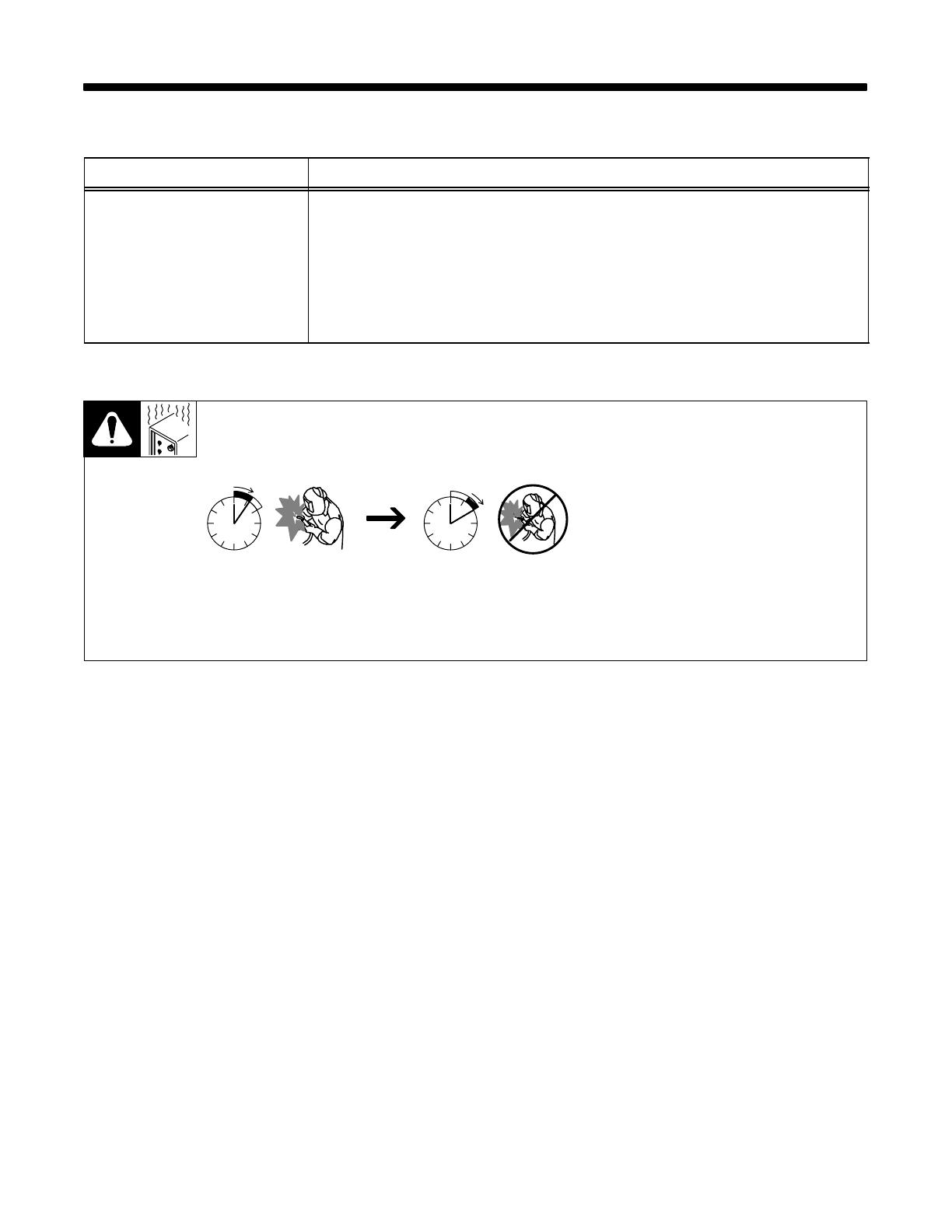
2-2. Duty Cycle
Duty Cycle is percentage of 10 min-
utes that unit can weld at rated load
without overheating.
If unit overheats, thermostat(s)
opens, output stops, and cooling
fan runs. Wait fifteen minutes for
unit to cool. Reduce amperage or
duty cycle before welding.
Y Exceeding duty cycle can
damage unit and void
warranty.
60% Duty Cycle At 250 Amperes
6 Minutes Welding 4 Minutes Resting
OM-534 Page 6
SECTION 3 – INSTALLATION
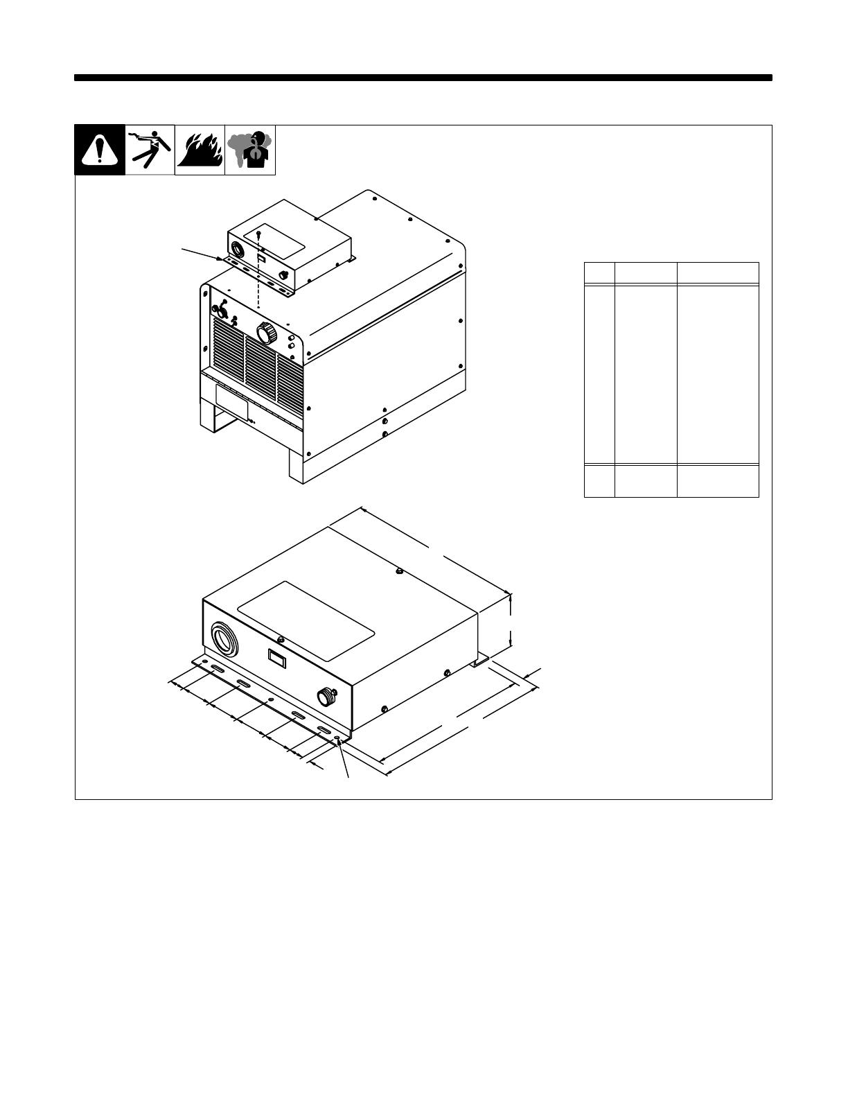
Inches Millimeters
A1 25
B2 51
C 1/2 13
D 10-3/4 273
E 11-1/2 292
F 3/8 10
G 3-5/8 92
H 11-5/8 295
J 1/4 Dia. 6 Dia.
14 Holes 14 Holes
ST-110 489-A / ST-110 488-B
1 Mounting Bracket
Use mounting bracket to secure
unit to welding power source or oth-
er convenient location.
1
A
C
D
E
G
H
J
A
B
B
B
B
F
3-1. Overall Dimensions And Installation
OM-534 Page 7
ST- 800 525 / ST-800 524
Remove wrapper.
1 Weld Cable
2 Positive (+) Terminal
3 Negative (–) Terminal
4 Reed Relay
See welding power source Owner’s
Manual for proper size weld cable.
Except for AC SMAW, route cable
through reed relay as shown.
For AC SMAW, reed relay is not
used. Remove relay by removing
two screws from bottom. Retain
relay for future use by reinstalling
where shown using existing mount-
ing holes.
Secure weld cables to terminals as
shown. Make remaining external
weld cable connections according
to Sections 3-4 and 3-5.
1
Tools Needed:
11/16 in
1/4 in
AC SMAW
To Welding Power Source
Electrode Output Terminal
All Other Connections
To Electrode Holder
2
3
1
4
1
2
3
1
4
3-2. Making Internal Weld Cable Connections
OM-534 Page 8
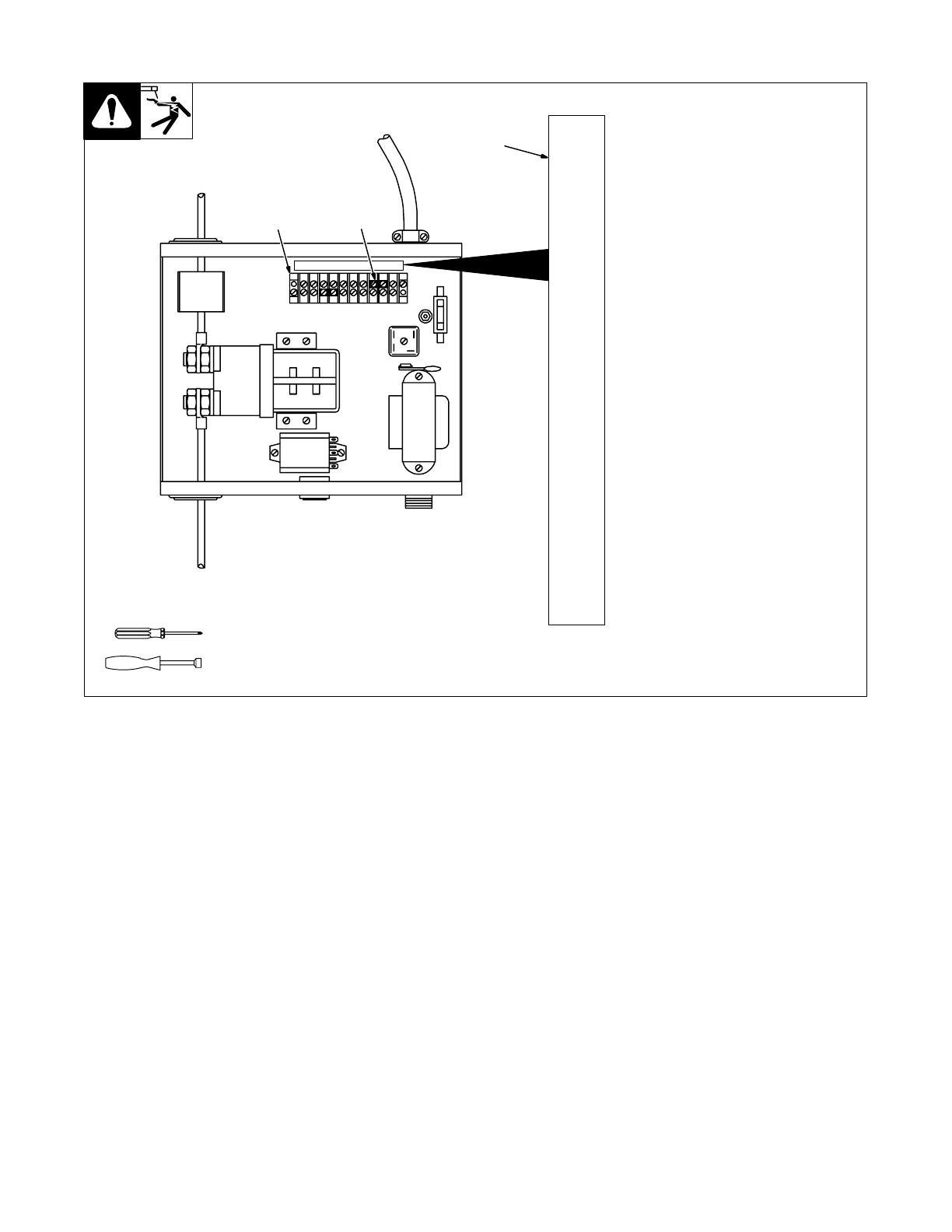
ST-800 524
1 Terminal Strip 1T
2 Connection Label
3 Trigger Hold Jumper Link
Use trigger hold only for DC SMAW.
Jumper link must be installed be-
tween terminals H and J as shown
for trigger hold.
Trigger hold operation: After arc
starts, contactor switch can be re-
leased and output stays on until arc
is broken.
Do not use trigger hold for AC
SMAW and GMAW. Remove jump-
er link to disable trigger hold.
Unit is shipped with jumper link in-
stalled.
Reinstall wrapper after all internal
connections are made.
1
Tools Needed:
1T
A
B
C
D
E
F
G
H
J
S-080 200-A
K
2
3
1/4 in
3-3. Trigger Hold Jumper Link

OM-534 Page 9
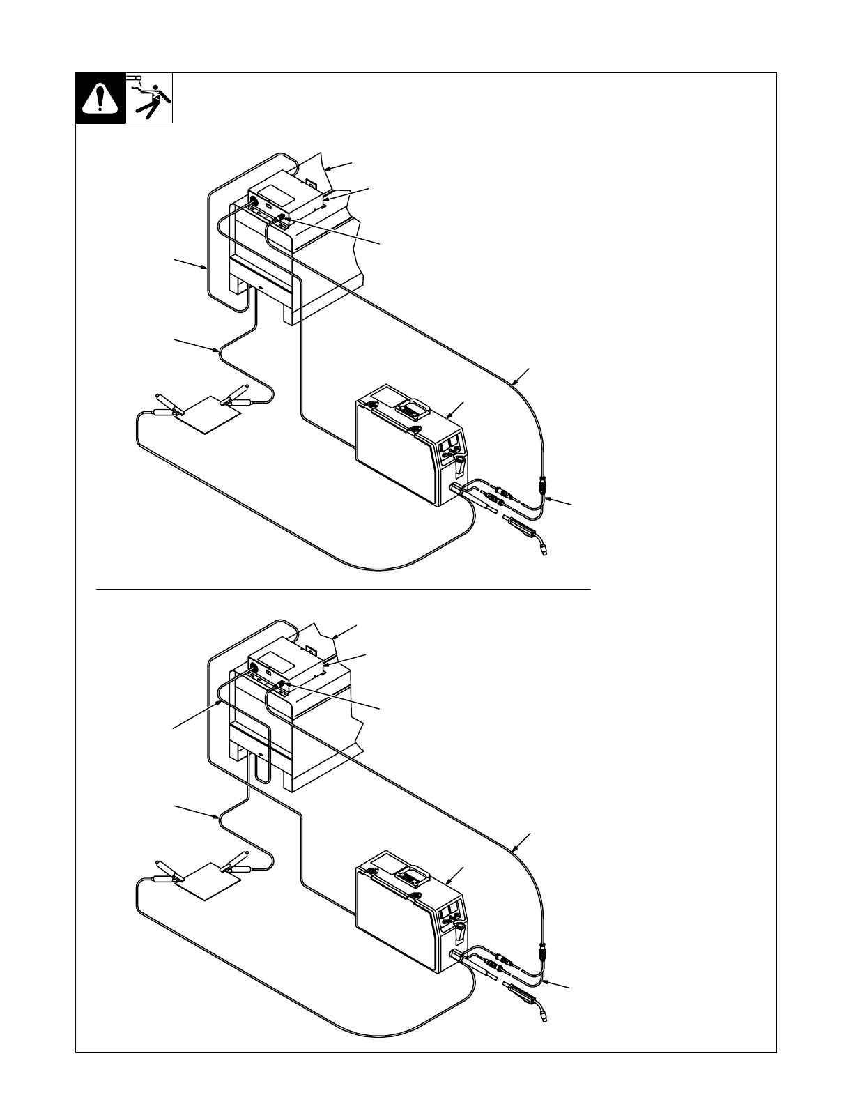
Ref. ST-800 529 / Ref. ST-800 530
1 Welding Power Source
2 Secondary Contactor
3 Positive (+) Weld Output
Cable
4 Negative (–) Weld Output
Cable
Make weld cable connections as
shown.
5 Trigger Receptacle
6 Electrode Holder With
Contactor Switch
Insert plug on contactor switch cord
into trigger receptacle, and tighten
threaded collar.
1
DC Electrode Positive
DC Electrode Negative
2
1
2
4
3
5
6
6
5
3
4
AC SMAW connections are
similar: Connect welding
power source electrode weld
cable to secondary contactor
positive (+) terminal, and
electrode holder cable to
negative (–) terminal (see
Section 3-2).
3-4. SMAW Connections
OM-534 Page 10
Ref. ST-800 527 / Ref. ST-800 528
1 Welding Power Source
2 Secondary Contactor
3 Voltage Sensing Wire Feeder
4 Positive (+) Weld Output
Cable
5 Negative (–) Weld Output
Cable
Make weld cable connections as
shown.
6 Interconnecting Cord
7 Remote Contactor Cord
8 Trigger Receptacle
Select and obtain proper remote
contactor and interconnecting
cords to make wire feeder, gun, and
trigger receptacle connections as
shown.
Match plugs and receptacles. To
connect, insert plug into receptacle,
and tighten threaded collar.
DC Electrode Positive
DC Electrode Negative
1
3
8
4
5
2
3
8
5
4
1
2
7
6
7
6
3-5. GMAW Connections
OM-534 Page 11
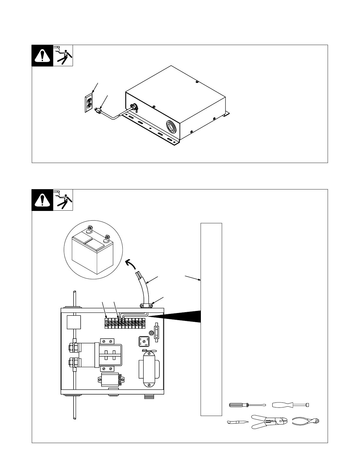
3-6. Connecting Input Power
A. 115 Volts AC Input Power
1 115 VAC Cord/Plug
2 115 VAC Grounded
Receptacle
Connect input power plug to weld-
ing power source or other 115 volts
ac receptacle.
ST-110 492-B
2
1
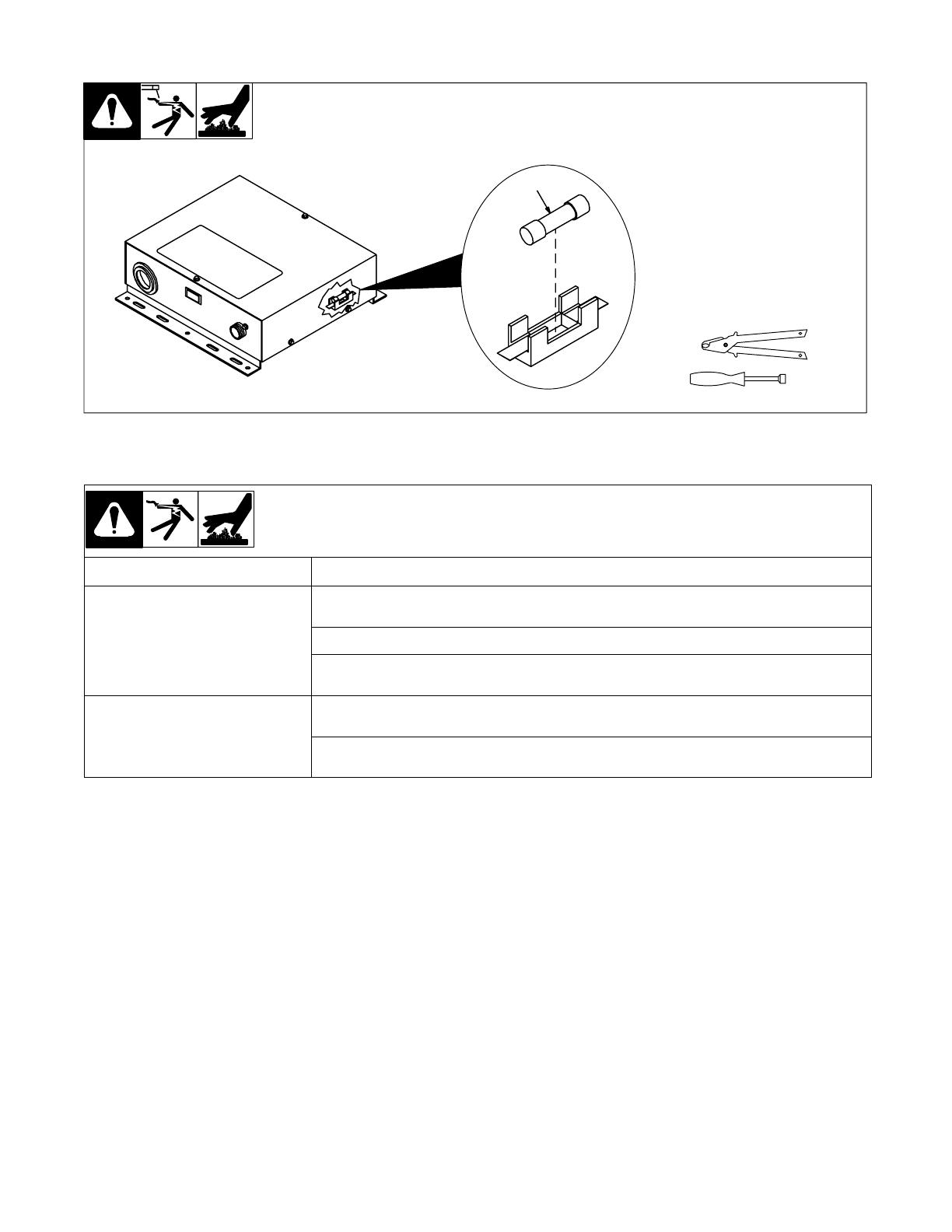
B. Optional 12 Volts DC Input Power Connections
ST-800 526
Have only qualified persons make
this installation.
Remove wrapper.
1 Terminal Strip 1T
2 Connection Label
3 Jumper Link Location
4 Strain Relief
5 Two-Conductor Cord
(Customer-Supplied)
Remove jumper link between 1T
terminals C and D.
Remove existing 115 volts ac pow-
er cord as follows: Loosen strain re-
lief, and disconnect power cord
leads to 1T and ground stud.
Obtain proper two-conductor cord.
Prepare leads, install connectors,
and route cord through strain relief.
Connect leads to terminals D and E
as shown. Tighten strain relief.
Connect leads on remaining end of
cord to 12 volts dc power supply;
polarity is not important.
Reinstall wrapper.
1
1T
A
B
C
D
E
F
G
H
J
S-080 200-A
K
2
3
5
4
Tools Needed:
1/4 in

OM-534 Page 12
SECTION 4 – OPERATION
ST-110 488-B / Ref. S-0621-C
1 Pilot Light
Pilot light goes on only when con-
tactor is energized.
SMAW operation: Press electrode
holder contactor switch to energize
contactor and start welding. Re-
lease switch or break arc to stop
welding.
If using trigger hold, switch can be
released after arc starts and weld-
ing continues. Break arc to stop
welding.
GMAW operation: Press gun trig-
ger to energize contactor and start
welding. Release trigger to stop
welding.
1
Trigger released: Contactor and pilot
light off, welding wire or electrode cold.
Trigger pressed: Contactor and pilot light
on, welding wire or electrode hot.
4-1. Contactor Operation
SECTION 5 – MAINTENANCE & TROUBLESHOOTING
Turn Off all power before maintaining.
ST-110 488-B
3 Months
OR
Blow Out
Or
Vacuum
Inside
Clean
And
Tighten
Weld
Terminals
Replace
Unreadable
Labels
6 Months
Tape Or
Replace
Cracked
Cables
5-1. Routine Maintenance
OM-534 Page 13
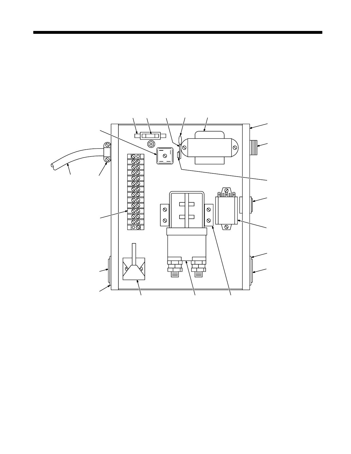
ST-800 531
Turn Off welding power source and
disconnect input power.
Remove wrapper.
1 Fuse F1 (See Parts List For
Rating)
If F1 opens, unit shuts down. Pull
fuse from fuse holder. To reinstall,
push fuse into fuse holder.
Reinstall wrapper.
1
Tools Needed:
1/4 in
5-2. Overload Protection: Fuse F1
5-3. Troubleshooting
Trouble Remedy
Secondary contactor does not close
when trigger switch is pressed.
Check fuse F1 and replace if needed (see Section 5-2).
Check all trigger connections (see Sections 3-4 and 3-5).
Have Factory Authorized Service Station/Service Distributor check trigger switch and contactor W, and
replace if necessary.
Secondary contactor does not open
when arc is broken.
Check for proper jumper link position on terminal strip 1T (see Section 3-3).
Have Factory Authorized Service Station/Service Distributor check control relay CR1, contactor W and
trigger switch, and replace if necessary.

OM-534 Page 14
SECTION 6 – ELECTRICAL DIAGRAM
SA-110 364
Figure 6-1. Circuit Diagram For Secondary Contactor

OM-534 Page 15
Notes
OM-534 Page 16
SECTION 7 – PARTS LIST
ST-110 490-A
12 3 4 5
6
7
8
9
10
11
12
15 14 13
18 17
16
12
11
19
. Hardware is common and
not available unless listed.
Figure 7-1. Complete Assembly
/