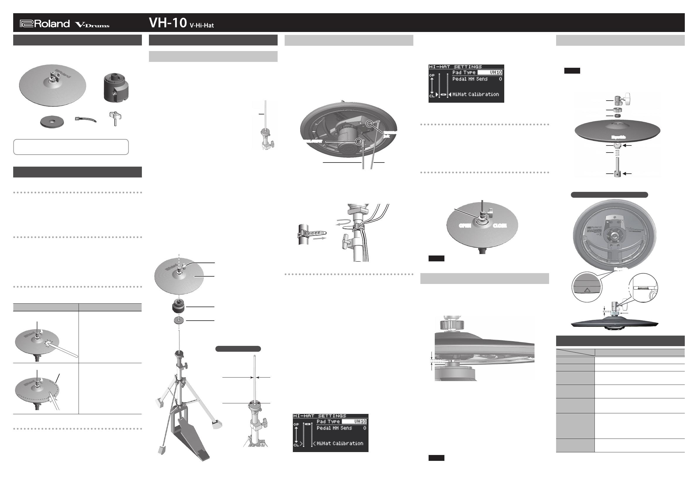
Check the Included Items
After opening the package, check that all of the included items
are present. If anything is missing, contact your dealer.
Hi-Hat
Motion Sensor
Unit
Drum keyLockable tieInsulating Plate
5 Owner’s Manual
5 Leaet “USING THE UNIT SAFELY”
* Hi-hat stand is not included.
Main Features
The Same Strike Feel as an Acoustic Hi-Hat
Since the VH-10 uses a single-cymbal oating design that can be
mounted on a commercially available hi-hat stand, it provides the
same playing feel as an acoustic hi-hat; when you strike it, the stick will
rebound and the cymbal will sway, and the cymbal moves up and down
in response to your pedal movement. The striking surface uses rubber
for good silencing.
Open/Close
The depth to which you advance the pedal of the hi-hat stand smoothly
varies the tonal character from open to closed. You can also use
techniques such as foot-close (pressing the pedal to sound the hi-hat)
or foot-splash (pressing the pedal and immediately opening it to sound
the hi-hat). With the VH-10 connected to a TD-50/TD-25 drum sound
module, you can express the tonal change that occurs when you strike
the hi-hat in the close state and then immediately open it.
Edge Shots Can Be Played
Since an edge sensor is built into the edge, you can dierentiate
between strikes on the bow (upper surface) and edge (circumference).
Playing method Explanation
Bow Shot
This playing method
involves striking the
middle area of the hi-hat. It
corresponds to the sound
of the “head-side” of the
connected trigger input.
Edge Shot
This playing method
involves striking the edge of
the hi-hat with the shoulder
of the stick. When played
as shown in the gure, the
“rim-side” sound of the
connected trigger input is
triggered.
Edge Sensor
Natural Pedal Feeling
By adjusting the depth of the pedal and the strength of the hi-hat
stand's spring, you can obtain the pedal feeling that you prefer.
Setup
Mounting the VH-10 on a Hi-Hat Stand
1. Remove the clutch included with the hi-hat
stand from the cymbal rod.
* The clutch included with the hi-hat stand will not be used.
* It is not necessary to remove the felt (or rubber) pad on the hi-hat
stand used for supporting the bottom cymbal.
2. Conrm that the cymbal rod is
rmly secured.
For instructions on tightening the cymbal rod, refer to
the owner’s manual for your cymbal stand.
* Looseness or play in the cymbal rod can make the
top hi-hat unstable, causing it to shake or turn, and
prevent proper functioning.
3. Place the insulating plate on the
hi-hat stand with the cymbal rod
passing through the hole of the insulating
plate.
Set the insulating plate with the sponge side facing up.
4. Place the motion sensor unit on the
insulating plate with the cymbal rod passing
through the hole of the motion sensor unit.
Position the CONTROL OUT jack on the farther side, as viewed from
the player.
5. Loosen the clutch screw and place the hi-hat
on the motion sensor unit with the cymbal
rod passing through the hi-hat hole.
The hi-hat should be oriented correctly. Positioning the “Roland” logo
at the back (as seen by the player) will provide the best sensitivity.
Clutch Screw
Hi-Hat
Motion Sensor Unit
CONTROL OUT jack on the
farther side
“Roland” logo on the
farther side
Sponge side up
Insulating Plate
* When turning the VH-10 upside down, protect the clutch and the
sensor from damage. Handle the unit with care so that it is not
dropped or overturned.
Connecting to a Sound Module
To prevent malfunction and equipment failure, always turn down the
volume, and turn o all the units before making any connections.
1. Connect the VH-10’s TRIGGER OUTPUT jack to
the sound module’s HI-HAT jack or cable, and
connect the VH-10’s CONTROL OUTPUT jack
to the sound module’s HH CTRL jack or cable.
TRIGGER OUTPUT
jack
CONTROL OUTPUT
jack
to the sound
module’s TRIGGER
INPUT HI-HAT jack
to the sound
module’s HH
CTRL jack
* Use stereo (TRS) cables to make the connections. If mono cables are
used, edge shots cannot be supported.
2. Allowing some slack in the cable, secure it
with the lockable tie.
Wind the
lockable tie
once
Tighten it not
to slip
Leave some slack in
the cables
Turn back to x the
cables
Adjusting the VH-10’s Oset for the TD-17
The VH-10’s oset must be adjusted so that open/close and
pedal movements can be detected correctly.
Here we explain how to make adjustments when using the
VH-10 in conjunction with the TD-17.
1. Conrm that the VH-10 and TD-17 are
connected properly.
2. After making the hi-hat settings, release your
foot from the pedal, and while keeping your
foot o the pedal, turn on the power to the
TD-17.
* The oset cannot be adjusted correctly if the hi-hat is making
contact with the motion sensor unit when the power is turned on.
3. Loosen the clutch screw and let the hi-hat
rest naturally on the motion sensor unit.
4. Press the [SETUP] button.
5. Use the dial to select “Hi-Hat Settings,” and
press the [ENTER] button.
6. Turn the dial to set Pad Type to “VH10.”
7. While reading the meter displayed on the
screen, adjust the oset with the VH-10’s
oset adjustment screw.
Adjust the oset so that [
JK
]appears in the meter.
8. Adjust other parameters as necessary.
Settings for other sound modules
1.
Set “Trigger Type” to “VH-11.”
2. As in step 7 above, turn the oset adjustment
screw to make adjustments.
3. Adjust other parameters as necessary.
Oset Adjustment Points
If the closed hi-hat sound is dicult to attain, rotate the oset
adjustment screw towards “CLOSE.”
If the open hi-hat sound is dicult to attain, rotate the screw
towards “OPEN.”
Oset
adjustment
screw
OPEN CLOSE
NOTE
If the sound cuts o when you strike the hi-hat forcefully, rotate the VH
oset adjustment screw towards “OPEN.”
Adjusting the Hi-Hat
1. Make adjustments so that the formed part in
the lower middle of the hi-hat is 3 mm away
from the center tip of the sensor, and then
tighten the clutch screw.
3mm3mm
* Although the gap can be adjusted to a clearance that makes
playing the hi-hat easier, setting too narrow or wide a gap can cause
improper function of the unit and prevent the hi-hat from sounding
as you intend. Setting the gap to 3 mm provides the most natural
feel when playing the VH-10.
2. Change the spring tension by adjusting the
hi-hat stand.
For instructions on adjusting the tension, refer to the
owner’s manual for your hi-hat stand.
* If the spring tension is too strong or too weak, the unit will malfunction, and
you might not be able to play the hi-hat as you intend.
* The tension may not be adjustable on some stands.
NOTE
The hi-hat should be oriented correctly. Positioning the “Roland” logo
at the back (as seen by the player) will provide the best sensitivity.
If the Clutch Was Apart from the Hi-Hat
If the hi-hat clutch is inadvertently removed from the hi-hat,
use the following procedure to reassemble and attach the
clutch.
NOTE
Due to the dierent shape, the clutch included with the hi-hat stand
cannot be used with the VH-10. Be sure to use the special VH-10
clutch.
Clutch Top
Rubber Washer
Player Side
Stopper (Upper) Be sure to orient it correctly.
Set the screw to front.
Spring
Stopper (Lower)
Oset Adjustment Screw
Position the “Roland” logo at the
back as seen by the player
* Orient the stopper (upper) so that it matches the groove in the
hi-hat.
Hi-Hat Being Properly Assembled
3 - 4mm
The oset adjustment screw
being fully tightened
The upper end of
the screw pipe of
the stopper can
be seen
Player Side
Main Specications
Roland VH-10: V-Hi-Hat
Size 12 inches
Trigger 2 (Bow, Edge)
Connectors
TRIGGER OUTPUT jack
CONTROL OUTPUT jack
Dimensions
314 (W) x 314 (D) x 103 (H) mm
12-3/8 (W) x 12-3/8 (D) x 4-1/16 (H) inches
Weight
1.2 kg 2 lbs 11 oz
(Excluding motion sensor unit)
Accessories
Owner’s Manual, Leaet “USING THE
UNIT SAFELY,” Motion sensor unit,
Insulating Plate, Drum key, Lockable tie,
Connection cable (only sold individually)
Options
(sold separately)
Noise Eater (NE-10, NE-1)
* The hi-hat’s rubber surface may turn white, but this has no eect on
the hi-hat’s function.
* This document explains the specications of the product at the
time that the document was issued. For the latest information, refer
to the Roland website.
Before using this unit, carefully read the leaet “USING THE UNIT SAFELY” and “IMPORTANT NOTES.”After reading, keep the
document(s) where it will be available for immediate reference.
English
Cymbal
Rod
Diameter: 6.0–7.0 mm
(1/4 to 5/16 inches)
Diameter: 11.7 mm
(1/2 inches) Max.
Compatible Stands
Copyright © 2018 ROLAND CORPORATION
Owner’s Manual