
INS #
Brand Logo
reversed out of
black
INS #
IB521008EN
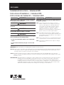
Installation Instructions – Celesteon LED
Instructions d’installation – Celesteon DEL
Instrucciones de instalación – Celesteon LED
IMPORTANT: Read carefully before installing fi xture. Retain for future reference.
WARNING
Make certain power is OFF before starting installation
or attempting any maintenance.
WARNING
Risk of Fire/Electric Shock. If not qualified, consult an
electrician.
WARNING
Risk of Electric Shock – Disconnect power at fuse or
circuit breaker before installing or servicing.
WARNING
Risk of Personal Injury – Fixture may become damaged
and/or unstable if not installed properly.
- Do not mount luminaire within 6” of a combustible
surface.
- Do not handle luminaire by the glass. Do not touch
LEDs.
WARNING
Risk of Burn – Disconnect power and allow fixture to
cool before servicing.
ote: N These instructions do not claim to cover all
details or variations in the equipment, procedure,
or process described, nor to provide directions
for meeting every possible contingency during
installation, operation or maintenance. When
additional information is desired to satisfy a
problem not covered sufficiently for user’s purpose,
please contact your nearest representative.
ote: N This lighting fixture has been shipped complete
with one of several mounting options. Please follow
the installation instructions specific to the catalog
part that you ordered.
ote: N Care must be taken not to set lighting fixture down
on optical lenses or lift the fixture in the lens area.
ote: N Specifications and dimensions subject to change
without notice.
General: Upon receipt of the fi xture, thoroughly inspect for any freight damage which should be brought to the attention
of the delivery carrier. Compare the catalog description listed on the packing slip with the fi xture label on the
housing to assure you have received the correct material.
Safety: This fi xture must be wired in accordance with the National Electrical Code and applicable local codes and
ordinances. Proper grounding is required to insure personal safety. Carefully observe grounding procedure under
installation section.
APPLICATIONS: This lighting fi xture is designed for outdoor lighting services, and should not be used in area of limited
ventilation or inside high ambient temperature enclosures. It must be stored in a dry location prior
to installation. Do not expose lighting fi xture to rain, dust or other environmental conditions prior to
installation and insertion of photo control or shorting cap (if so equipped). Do not install the fi xture near
combustible materials or locate next to airfl ow blocking surfaces within 6 inches. Best results will be
obtained if installed and maintained according to the following recommendations.

2
EATON IB521008EN Installation instructions
Installation Instructions – Celesteon LED
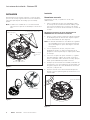
INSTALLATION
This lighting fixture has been shipped complete with one
of several mounting options. Please follow the installation
instructions specific to the catalog part that you ordered.
ote: N Care must be taken not to set lighting fixture down
on optical lenses or lift the fixture in the lens area.
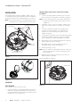
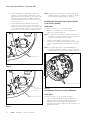
Figure 1.
Figure 2.
Figure 3.
Installation
Tools Required
3/8” socket, ¾” socket, Torque wrench
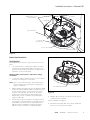
1. Use lowering device to bring the luminaire mounting
ring down to working height. Make a visual check of
the pole and anchor bolts. Determine the placement of
luminaires on the mounting ring.
1/4-20 Captive Bolts (4x)
1/2” Hex
Bolts (4x)
Vertical Adjustment Steps
Hinge Option
5/16 Bolts (4x)
Safety Chain
Warning: Make certain power is OFF before starting
installation
2. Loosen four captive ¼-20 hex head screws to remove
driver housing cover using 3/8” socket driver. (Figure 1.)
ote: N Cover is tethered with a 12 inch safety chain unless
luminaire has a hinge option. Hinge option is shown
in (Figure2.)
3. Using 3/4” socket, loosen the four pipe clamps ½ inch
hex bolts enough to allow for clearance for mounting
arm.
4. Select the desired +/-5 degree vertical adjustment
steps for the mounting arm to sit on and slide the
luminaire onto the mounting arm. Support it until
clamps can hold it.
5. Check that the luminaire is level (level indicator provided
as optional inside the luminaire see Figure 2). Tighten
all four clamps down evenly and tighten to 35 ft lbs.
6. Recheck the level of luminaire after bolts are torqued to
assure alignment was not affected.
7. Pull supply wires out of mounting arm. Connect
luminaire leads per wiring section below.
8. Ensure all wiring is secure.
ote: N Check to make sure that supply wires are connected
within the junction box on the mounting ring of the
lowering device.
9. Replace driver housing cover and re-secure the four
¼-20 hex bolts to 10 in lbs.
Caution: DO NOT over tighten.

3
EATON IB521008EN Installation instructions
Installation Instructions – Celesteon LED
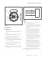
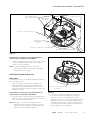
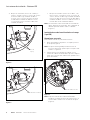
Figure 4.
Figure 5.
Optical Orientation
Tools Required
½” Socket; Torque wrench
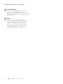
1. With the driver housing cover opened, loosen four
5/16” hex head bolts no more than two turns using ½”
socket.
Caution: DO NOT loosen more than two turns and do not
loosen the three tamper proof safety bolts.
2. Rotate the LED optical casting as desired. Follow the
angle markings on the cap during rotation.
ote: N From the 0 degree point denoted by arrow on
the cap, the LED optical assembly will rotate 180
degrees in one direction and 165 degrees in opposite
direction. See (Figure 4).
Caution: Ensure wires do not get strained during rotation.
3. Retighten the four hex bolts to 25 ft lbs and ensure
LED optical assembly will not rotate.
4. Tighten the two ¼-20 Allen set screws to 12 ft lbs.
ote: N Follow this step even if optical orientation adjustment
is not needed as these set screws are not factory
tightened.
Wiring
1. Pull service wires through the mounting arm and into
the housing approximately 10 inch.
a. Three-terminal block (2-wire service): Connect line
service lead to terminal that is connected to black
factory-installed wire. Connect neutral service wire
to terminal that is connected to white factory-
installed wire.
b. Three-terminal block (3-wire service, 1 lines, 1
ground): Connect line service lead to terminal
that is connected to black factory-installed wire.
Connect other line service lead to terminal that
is connected to white factory installed wire.
Connect the ground service lead to terminal that is
connected to green factory installed wire.
c. Three-terminal block (3-wire service, 1 line, 1
neutral, 1 ground): Connect line service lead to
terminal that is connected to black factory installed
wire. Connect neutral service wire to terminal
that is connected to white factory installed wire.
Connect ground service wire to terminal that is
green factory installed wire.
d. No terminal block (3 wire service, 2 lines, 1
ground): Connect 1 line service lead to black
factory installed wire. Connect other line service
lead to white factory installed wire. Connect
ground service lead to green factory installed wire.
e. No terminal block (3 wire service, 1 line, 1 neutral,
1 ground): Connect line service lead to black
factory installed wire. Connect neutral service wire
to white factory installed wire. Connect ground
service wire to green factory installed wire.
ote: N Terminals are numbered at wire entrance of the
terminal block. See wiring diagram for additional wire
details. (Figure 5.)
(+) Line
(-) Common
Ground
Wiring Diagram
Black
White
Fixture
Green
Traffic Direction
165 ° rotation
this direction
1/4-20 Set
Screws (2X)
5/16 Bolts (4X)
1/4-20
Safety
Bolts (3X)
180 ° rotation
this direction

4
EATON IB521008EN Installation instructions
Installation Instructions – Celesteon LED
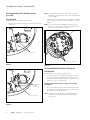
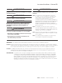
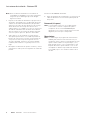
Field Installed House Side Shield Installation
(1perLED)
Tools Required
#2 Phillips head screw driver, torque wrench
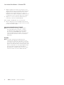
1. Remove two plastic push pins on the back side of optic
(Figure 6).
ote: N The optics are permanently secured to the fixture.
DO NOT try to remove the optics. The individual optic
is not rotatable.
2. Install house side shield with provided #10 X ½” Phillips
screws. Tighten until house shield is snug. Do not over
Tighten.
ote: N House side shield must ONLY be installed on the
back side of the optics as shown. DO NOT install on
the other side of the optic. (Figure 7).
Figure 6.
Figure 7.
Figure 8.
Field Installed Shield Installation (180degree)
Tools Required
#2 Phillips head screw driver, torque wrench
1. Use lowering device to bring the luminaire mounting
ring down to working height. Make a visual check of
the pole and anchor bolts. Determine the placement of
luminaires on the mounting ring.
Warning: Make certain power is OFF before starting
installation
2. Once the shield location has been determined, mount
the shield onto the LED plate using four 10-24 screws
provided and torque to 20 in lbs.
ote: N 180 degree shield can be mounted at 45 degree
increments onto the LED plate via eight different
mount points.
Push Pins
Back
Front
House Side Shield
#10-24 X 1/2” Screws (4x)
#10-24 X 5/8”
Phillips
Screws (2x)

5
EATON IB521008EN Installation instructions
Installation Instructions – Celesteon LED
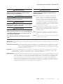
Figure 10.
Figure 9.
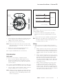
Nature Guard Installation
Tools Required
#2 Phillips head screw driver, torque wrench, 3/8” socket,
pliers
1. Use lowering device to bring the luminaire mounting
ring down to working height. Make a visual check of
the pole and anchor bolts. Determine the placement of
luminaires on the mounting ring.
Warning: Make certain power is OFF before starting
installation
2. Loosen four captive ¼-20 hex screws to remove driver
housing cover using 3/8” socket driver.
ote: N Note: cover is tethered with a 12 inch safety chain
unless luminaire has a hinge option. Hinge option
Figure 2 mechanical.
3. Nature guard is provided in two pieces, labeled A and B
(Figure 9). Slide the Nature Guard A, top tabs (2x), over
the two mount location of the housing cover mount
locations. Carefully align the cutouts on the nature
guard over the led housing fins and install the two
10-24X3/8” screws to hold the first guard in place.
Tighten to 20 in lbs.
4. Follow step 3 with the other piece on opposite side of
the first piece. Carefully align the locking tab from one
guard and insert into slots of the other guard. Once
tabs are in place and aligned, install remaining two
#10-24 screws to hold the second guard in place.
#10-24 x 3/8” Screws
(2X per Guard)
Locking Tab
Nature Guard (A)
Locking Tab
(4x per guard)
Slots for locking tab
Nature Guard (B)
Top Tab (2x
per Guard)
5. Replace driver housing cover and re-secure the four
¼-20 hex bolts to 10 in lbs.
Caution: DO NOT over tighten.
6. Bend the interlocking tabs on the nature guard with
pliers to lock the two pieces in place.
Assembled Nature Guard

6
EATON IB521008EN Installation instructions
Installation Instructions – Celesteon LED
Photocontrol (If Equipped)
ote: N If your luminaire is equipped with a photocontrol
receptacle, see IB525002EN Photocontrol
Receptacle Supplement to identify your photocontrol
and follow the instructions on the diagram and all the
applicable notes.
Maintenance
ote: N A regular maintenance schedule should be
followed to retain optimal light output and thermal
performance. Optical lens cleaning should be
performed with a clean dry cloth to remove any
dust or other contaminants. Additional cleaning
can be performed with using a non-abrasive to
polycarbonate cleaner. Remove any dirt, leaves or
other foreign debris from the housing.
Page is loading ...
Page is loading ...
Page is loading ...
Page is loading ...
Page is loading ...
Page is loading ...
Page is loading ...
Page is loading ...
Page is loading ...
Page is loading ...
Page is loading ...
Page is loading ...

Eaton
1121 Highway 74 South
Peachtree City, GA 30269
P: 770-486-4800
www.eaton.com/lighting
Canada Sales
5925 McLaughlin Road
Mississauga, Ontario L5R 1B8
P: 905-501-3000
F: 905-501-3172
© 2018 Eaton
All Rights Reserved
Printed in USA
Imprimé aux États-Unis
Impreso en los EE. UU.
Publication No. IB521008EN
February 26, 2018
Eaton is a registered trademark.
All trademarks are property
of their respective owners.
Eaton est une marque de commerce
déposée. Toutes les autres marques
de commerce sont la propriété de leur
propriétaire respectif.
Eaton es una marca comercial
registrada. Todas las marcas
comerciales son propiedad de sus
respectivos propietarios.
Product availability, specifications,
and compliances are subject to
change without notice
La disponibilité du produit, les
spécifications et les conformités
peuvent être modifiées sans préavis
La disponibilidad de productos, las
especificaciones y los cumplimientos
están sujetos a cambio sin previo aviso
Warranties and Limitation of Liability
Please refer to www.eaton.com/LightingWarrantyTerms for our terms and conditions.
Garanties et limitation de responsabilité
Veuillez consulter le site www.eaton.com/LightingWarrantyTerms pour obtenir les conditions générales.
Garantías y Limitación de Responsabilidad
Visite www.eaton.com/LightingWarrantyTerms para conocer nuestros términos y condiciones.
-
 1
1
-
 2
2
-
 3
3
-
 4
4
-
 5
5
-
 6
6
-
 7
7
-
 8
8
-
 9
9
-
 10
10
-
 11
11
-
 12
12
-
 13
13
-
 14
14
-
 15
15
-
 16
16
-
 17
17
-
 18
18
-
 19
19


Cooper Lighting CST Celesteon Installation guide
- Type
- Installation guide
- This manual is also suitable for
Ask a question and I''ll find the answer in the document
Finding information in a document is now easier with AI
in other languages
Related papers
-
Cooper Lighting QD Quadcast Installation guide
-
Eaton VRDN Installation guide
-
-
-
-
Eaton SDL LED Arm Mount Installation guide
-
-
-
-
Other documents
-
Faro 20040-122 Operating instructions
-
Howard FLL Series LED Flood Light User manual
-
SATCO NUVO 65-534R1 User manual
-
Halco SDD-WS-CS-U-GR-3PR Installation guide
-
Metalux 24FP6440C Installation guide
-
 Lumark NFFLD-S-C15-T-UNV Installation guide
-
Cooper USSL Installation Instructions Manual
-
-
-
C-LITE C-LITE C-CP-B-BRQ Series User manual
