Page is loading ...

Cover photo may show optional equipment
not supplied with standard unit.
© Copyright 2007 Printed
Read the Operator’s manual entirely. When
you see this symbol, the subsequent
instructions andwarnings are serious - follow
without exception. Your life and the lives of
others depend on it!
!
Table of Contents
24864
3/21/07
309-523M
Operator’s Manual
FM3188 & FM4188
Flail Mowers

Table of Contents
© Copyright 2007 All rights Reserved
Land Pride provides this publication “as is” without warrantyof any kind, eitherexpressedor implied.While every precautionhas beentaken in the preparation ofthis manual, Land
Pride assumesnoresponsibilityfor errorsoromissions.Neitheris anyliabilityassumed fordamagesresultingfromthe use oftheinformation containedherein. Land Pride reserves
the rightto reviseandimprove itsproductsas it seesfit.This publicationdescribes thestateof this productatthe time ofitspublication,andmay notreflect the productinthefuture.
Land Pride is aregistered trademark.
All other brands and product names are trademarks or registered trademarks oftheir respective holders.
Printed in the United States of America.
Land Pride
Table of Contents
FM3188 & FM4188 Flail Mowers 309-523M
3/21/07
Important Safety Information . . . . . . . . . . .1
Safety at All Times . . . . . . . . . . . . . . . . . . . . . . . . . 1
Look For The Safety Alert Symbol . . . . . . . . . . . . .1
Safety Labels . . . . . . . . . . . . . . . . . . . . . . . . . . . . . 4
Introduction . . . . . . . . . . . . . . . . . . . . . . . .7
Application . . . . . . . . . . . . . . . . . . . . . . . . . . . . . . . 7
Using This Manual . . . . . . . . . . . . . . . . . . . . . . . . . 7
Terminology . . . . . . . . . . . . . . . . . . . . . . . . . . . 7
Definitions . . . . . . . . . . . . . . . . . . . . . . . . . . . . . 7
Owner Assistance . . . . . . . . . . . . . . . . . . . . . . . . . 7
Serial Number Plate . . . . . . . . . . . . . . . . . . . . .7
Further Assistance . . . . . . . . . . . . . . . . . . . . . . 8
Section 1: Assembly and Set-up . . . . . . . .9
Tractor Requirements . . . . . . . . . . . . . . . . . . . . . . 9
Hitch Assembly . . . . . . . . . . . . . . . . . . . . . . . . . . . 9
Tractor Hook-Up . . . . . . . . . . . . . . . . . . . . . . . . . 10
Driveline Installation . . . . . . . . . . . . . . . . . . . . . . . 10
Driveline Minimum Length . . . . . . . . . . . . . . . .11
Driveline Maximum Allowable Length . . . . . . .11
Section 2: Operating Instructions . . . . . .12
Transporting . . . . . . . . . . . . . . . . . . . . . . . . . . . . 12
Mowing Instructions . . . . . . . . . . . . . . . . . . . . . . . 12
Brush Rake Teeth . . . . . . . . . . . . . . . . . . . . . . . . 12
Operating Instructions . . . . . . . . . . . . . . . . . . . . . 12
General Operating Instructions . . . . . . . . . . . . . .13
Section 3: Adjustments . . . . . . . . . . . . . .14
Leveling the Mower . . . . . . . . . . . . . . . . . . . . . . . 14
Cutting Height Adjustment . . . . . . . . . . . . . . . . . . 14
Mower Hitch Adjustments . . . . . . . . . . . . . . . . . . 14
Belt Tension Adjustment . . . . . . . . . . . . . . . . . . . 15
Brush Rake Teeth Adjustment . . . . . . . . . . . . . . . 15
Section 4: Maintenance and Lubrication 16
Maintenance . . . . . . . . . . . . . . . . . . . . . . . . . . . .16
Trash Removal & Rotor Knife Access . . . . . . . . .16
Rotor Knife Replacement . . . . . . . . . . . . . . . . . . .16
FM3188 Cutting Knife Replacement . . . . . . . .17
FM4188 Hammer Knife Replacement . . . . . . .17
V-Belt Installation . . . . . . . . . . . . . . . . . . . . . . . . .17
Storage . . . . . . . . . . . . . . . . . . . . . . . . . . . . . . . .17
Lubrication . . . . . . . . . . . . . . . . . . . . . . . . . . . . . .18
Driveline Shaft U-Joints . . . . . . . . . . . . . . . . . .18
Driveline Profiles . . . . . . . . . . . . . . . . . . . . . . .18
Inner Tube Bearings . . . . . . . . . . . . . . . . . . . .18
Gearbox . . . . . . . . . . . . . . . . . . . . . . . . . . . . .19
3-Point Hitch Slide . . . . . . . . . . . . . . . . . . . . . .19
Roller Bearing (Both Ends) . . . . . . . . . . . . . . .20
Cutter Rotor Bearing (Both Ends) . . . . . . . . . .20
Section 5: Specifications & Capacities . .21
Section 6: Features and Benefits . . . . . .22
Section 7: Troubleshooting . . . . . . . . . . .23
Section 8: Appendix . . . . . . . . . . . . . . . . .24
Torque Values Chart . . . . . . . . . . . . . . . . . . . . . .24
Warranty . . . . . . . . . . . . . . . . . . . . . . . . . . . . . . .25

1
Important Safety Information
3/21/07
FM3188 & FM4188 Flail Mowers 309-523M
Land Pride
Table of Contents
Important Safety Information
Safety at All Times
Thoroughly read and understand
the instructions given in this
manual before operation. Refer to
the “Safety Label” section, read
all instructions noted on them.
Do not allow anyone to operate
this equipment who has not fully
read and comprehended this
manual and who has not been
properly trained in the safe
operation of the equipment.
▲ Operator should be familiar with
all functions of the unit.
▲ Operate implement from the
driver’s seat only.
▲ Make sure all guards and shields
are in place and secured before
operating the implement.
▲ Do not leave tractor or implement
unattended with engine running.
▲ Dismounting from a moving
tractor could cause serious injury
or death.
▲ Do not stand between the tractor
and implement during hitching.
▲ Keep hands, feet, and clothing
away from power-driven parts.
▲ Wear snug fitting clothing to avoid
entanglement with moving parts.
▲ Watch out for wires, trees, etc.,
when raising implement. Make
sure all persons are clear of
working area.
▲ Turning tractor too tight may
cause implement to ride up on
wheels. This could result in injury
or equipment damage.
!
Look For The Safety Alert Symbol
The SAFETY ALERT SYMBOL indicates there is a
potential hazard to personal safety involved and extra
safety precaution must be taken. When you see this
symbol, be alert and carefully read the message that
follows it. In addition to design and configuration of
equipment, hazard control and accident prevention
are dependent upon the awareness, concern,
prudence and proper training of personnel involved in
the operation, transport, maintenance and storage of
equipment.
Be Aware of
Signal Words
A Signal word designates a degree or
level of hazard seriousness. The
signal words are:
Indicates an imminently hazardous
situation which, if not avoided, will
result in death or serious injury. This
signal word is limited to the most
extreme situations, typically for
machine components that, for
functional purposes, cannot be
guarded.
!
DANGER
Indicates a potentially hazardous
situation which, if not avoided, could
result in death or serious injury, and
includes hazards that are exposed
when guards areremoved. It may also
be used to alert against unsafe
practices.
Indicates a potentially hazardous
situation which, if not avoided, may
result in minor or moderate injury. It
may also be used to alert against
unsafe practices.
!
WARNING
!
CAUTION
For Your Protection
▲ Thoroughly read and understand
the “Safety Label” section, read all
instructions noted on them.
Shutdown and Storage
▲ Lower machine to ground, put
tractor in park, turn off engine, and
remove the key.
▲ Detach and store implements in a
area where children normally do
not play. Secure implement by
using blocks and supports.
OFF
REMO
VE
These are common practices that may or may not be applicable to the products described in
this manual.

2
Important Safety Information
FM3188 & FM4188 Flail Mowers 309-523M
3/21/07
Land Pride
Table of Contents
Transport
Machinery Safely
▲ Comply with state and local laws.
▲ Maximum transport speed for
implement is 20 mph. DO NOT
EXCEED. Never travel at a speed
which does not allow adequate
control of steering and stopping.
Some rough terrain require a
slower speed.
▲ Sudden braking can cause a
towed load to swerve and upset.
Reduce speed if towed load is not
equipped with brakes.
▲ Use the following maximum
speed - tow load weight ratios as
a guideline:
20 mph when weight is less
than or equal to the weight of
tractor.
10 mph when weight is double
the weight of tractor.
▲ IMPORTANT: Do not tow a load
that is more than double the
weight of tractor.
Use Safety
Lights and Devices
▲ Slow moving tractors, self-
propelled equipment, and towed
implements can create a hazard
when drivenonpublicroads.They
are difficult to see, especially at
night.
▲ Flashing warning lights and turn
signals are recommended
whenever driving on public roads.
Use lights and devices provided
with implement.
Practice Safe Maintenance
▲ Understand procedure before
doing work. Use proper tools and
equipment, refer to Operator’s
Manual for additional information.
▲ Work in a clean dry area.
▲ Lower the implement to the
ground, put tractor in park, turn off
engine, and remove key before
preforming maintenance.
▲ Allow implement to cool
completely.
▲ Do not grease or oil implement
while it is in operation.
▲ Inspect all parts. Make sure parts
are in good condition & installed
properly.
▲ Remove buildup of grease, oil or
debris.
▲ Remove all tools and unused
parts from implement before
operation.
These are common practices that may or may not be applicable to the products described in
this manual.

3
Important Safety Information
3/21/07
FM3188 & FM4188 Flail Mowers 309-523M
Land Pride
Table of Contents
Prepare for Emergencies
▲ Be prepared if a fire starts.
▲ Keep a first aid kit and fire
extinguisher handy.
▲ Keep emergency numbers for
doctor, ambulance, hospital and
fire department near phone.
911
Wear
Protective Equipment
▲ Protectiveclothing and equipment
should be worn.
▲ Wear clothing and equipment
appropriate for the job. Avoid
loose fitting clothing.
▲ Prolonged exposure to loud noise
can cause hearing impairment or
hearing loss. Wear suitable
hearing protection such as
earmuffs or earplugs.
▲ Operating equipment safely
requires the full attention of the
operator. Avoid wearing radio
headphones while operating
machinery.
Keep Riders
Off Machinery
▲ Riders obstruct the operator’s
view, they could be struck by
foreign objects or thrown from the
machine.
▲ Never allow children to operate
equipment.
These are common practices that may or may not be applicable to the products described in
this manual.

4
Important Safety Information
FM3188 & FM4188 Flail Mowers 309-523M
3/21/07
Land Pride
Table of Contents
818-130C
Caution: To avoid injury
24864
Safety Labels
Your Flail Mower comes equipped with all safety labels in
place. They were designed to help you safely operate your
implement. Read and follow their directions.
1. Keep all safety labels clean and legible.
2. Replace all damaged or missing labels. To order new
labels go to your nearest Land Pride dealer or visit our
dealer locator at landpride.com.
3. Some new equipment installed during repair requires
safety labels to be affixed to the replaced component as
specified by Land Pride. When ordering new components
make sure the correct safety labels are included in the
request.
4. Refer to this section for proper label placement.
To install new labels:
a. Clean the area the label is to be placed.
b. Spray soapy water on the surface where the label is to
be placed.
c. Peel backing from label. Press firmly onto the surface.
d. Squeeze out air bubbles with the edge of a credit card.
24864
24864
818-543C
Danger: Guard Missing


7
Introduction
3/21/07
FM3188 & FM4188 Flail Mowers 309-523M
Land Pride
Table of Contents
Introduction
Terminology
“Right” or “Left” as used in this manual is determined by
facing the direction the machine will operate while in use
unless otherwise stated.
Definitions
Owner Assistance
The Warranty Registration card should be filled out by
the dealer at the time of purchase. This information is
necessary to provide you with quality customer service.
If customer service or repair parts are required contact a
LandPridedealer. Adealerhas trainedpersonnel,repair
parts and equipment needed to service the mower.
The parts on your Flail Mower have been specially
designedandshouldonlybereplacedwithgenuineLand
Pride parts. Therefore, should your mower require
replacement parts go to your Land Pride Dealer.
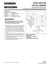
Serial Number Plate
For prompt service always use the serial number and
modelnumber when ordering partsfrom your Land Pride
dealer.Besuretoincludeyourserialandmodel numbers
incorrespondencealso.Referto Figure1 forthe location
of your serial number plate.
Serial Number Plate Location
Figure 1
NOTE: A special point of information that the
operator must be aware of before continuing.
IMPORTANT: A special point of information related
to its preceding topic. Land Pride’s intention is that
this information should be read and noted before
continuing.
24865
Land Pride welcomes you to the growing family of new
product owners. This implement has been designed with
care and built by skilled workers using quality materials.
Proper assembly, maintenance, and safe operating
practices will help you get years of satisfactory use from
this product.
Application
The heavy duty FM3188 and FM4188 Series Flail
Mowers are designed and built to provide excellent
cutting performance on gently sloping or slightly
contoured right-of ways, roadsides, ditches, pastures,
nurseries, and smaller fields of row crop debris, stalks,
and residual agricultural growth.
Both are capable of cutting 88” wide and 1/2" to 6" high.
The three-point Cat. I hitch is designed to be used on
tractorswithamaximum80PTOhorsepower.Theirhitch
isdesigned with a screw type crank adjustment for 7 3/4"
offset capability to the left or right making this mower
even more desirable for cutting in and around trees with
extremely low hanging branches. Its horizontal rotor
cutting design greatly reduces the potential of launching
projectiles out from under the mower making it an
excellent choice for state and municipal mowing
applications. Both models are complete with a 540 rpm
Cat. 4 driveline.
The FM3188 model equipped with fine cutting knives will
perform extremely well cutting material up to 1" in
diameter or provide a very respectable quality of cut for
grooming yards, municipal parks, medians, and right of
ways.
The FM4188 model equipped with forged hammer
knives and heavy duty brush rake teeth make this model
well suited for nursery and agricultural applications
where heavy grass, brush, prunings, saplings, small
stumps, corn stocks and other row crop debris are
present. The rake teeth will gather and aggressively
force material into the rotor hammer knives for a more
complete pulverization.
See “Specifications & Capacities” on page 21 and
“Features and Benefits” on page 22 for additional
information and performance enhancing options.
Using This Manual
•
This Operator’s Manual is designed to help familiarize
you with safety, assembly, operation, adjustments,
troubleshooting, and maintenance. Read this manual
and follow the recommendations to help ensure safe
and efficient operation.
• The information contained within this manual was
current at the time of printing. Some parts may change
slightly to assure you of the best performance.
• To order a new Operator’s or Parts Manual contact
your authorized dealer. Manuals can also be
downloaded, free-of-charge from our website at
www.landpride.com or printed from the Land Pride
Service & Support Center by your dealer.

8
Introduction
FM3188 & FM4188 Flail Mowers 309-523M
3/21/07
Land Pride
Table of Contents
Further Assistance
Your dealer wants you to be satisfied with your new Flail
Mower. If for any reason you do not understand any part
of this manual or are not satisfied with the service
received, the following actions are suggested:
1. Discuss the matter with your dealership service
manager making sure he is aware of any problems
youmay have and that he has had the opportunity to
assist you.
2. If you are still not satisfied, seek out the owner or
general manager of the dealership, explain the
problem and request assistance.
3. For further assistance write to:
Land Pride Service Department
1525 East North Street
P.O. Box 5060
Salina, Ks. 67402-5060
E-mail address
lpser[email protected]

9
Section 1: Assembly and Set-up
3/21/07
FM3188 & FM4188 Flail Mowers 309-523M
Land Pride
Table of Contents
Hitch Assembly
Figure 1-1
24866
Section 1: Assembly and Set-up
2. Remove lock nut (#13) and bolt (#12). Pull
adjustment rod (#7) back as shown.
3. Assemblehitch(#1)toFlailMowerbyinsertingupper
tube (#2) through hitch tube (A), spacer tube (B),
hitch tube (C) and into retaining collar (D).
4. Secure upper tube with bolt (#4) and lock nut (#5).
5. Insert lower tube (#3) through lower hitch tube (E)
and into retaining collar (F).
6. Secure lower tube with bolt (#4) and lock nut (#5).
7. With hand crank(#6), screw adjustment rod (#7) into
adjustment block (#8) until washer (#9) is tight
against the side panel.
8. Press washer (#10) against the side panel. Insert
bolt (#12) through retaining collar (#11) and
adjustment rod (#7). Secure with lock nut (#13).
9. Return hand crank (#6) to its carrying tube (G).
10. Tighten all hardware. Refer to “Torque Values
Chart for Common Bolt Sizes” Page 24.
Tractor Requirements
Tractor horse power rating should be between 35 & 80
PTO horsepower. Tractors outside this horsepower
range must not be used.
The rear power take-off (PTO) speed must be capable
540 RPM and have a 1 3/8”-6 spline.
A 3-Point Category I or ll hitch is required. The lower
3-Point arms must be stabilized to prevent side-to-side
movement.Mosttractors haveswayblocksoradjustable
chains for this purpose.
Hitch Assembly
Refer to Figure 1-1:
The hitch is disassembled for ease in shipping.
1. Remove lock nuts (#5) and bolts (#4).
Pull tubes (#2) and (#3) back as shown.
NOTE: Ballast may need to be added to your tractor
to maintain steering control. Refer to your tractor’s
operator manual to determine if additional ballast is
needed.

10
Section 1: Assembly and Set-up
FM3188 & FM4188 Flail Mowers 309-523M
3/21/07
Land Pride
Table of Contents
Maximum Allowable Driveline Movement
Figure 1-3
IMPORTANT: Some tractors are equipped with
multispeed PTO ranges. Be certain your tractor ‘s
PTO is set for 540 rpm.
IMPORTANT: See Figure 1-3 below. Avoid
premature driveline breakdown. A driveline that is
operating must not exceed an angle of 25 degrees
up or down while operating the 3-point lift.
24872
IMPORTANT: Always check driveline minimum
length and maximum allowable length during initial
setup and when connecting to a different tractor.
More than one driveline may be required to fit all
applications.
IMPORTANT: It is necessary to align the tractor’s
PTO shaft level with the gearbox shaft when
checking driveline minimum length. Too long a
driveline can damage tractor, gearbox and driveline.
Tractor Hook-Up
Figure 1-2
24867
Tractor Hook-Up
Refer to Figure 1-2:
1. Be certain tractor draw bar does not interfere. Move
draw bar ahead or remove if required. Draw bar
should also be checked for clearance when unit is
raised for the first time.
2. Remove all three clevis hitch pins.
3. Align ball swivels in the tractor’s lower 3-point arms
with pin holes in the mower’s lower hitch clevises.
Insert hitch pins and secure with hair pin cotters.
4. Alignthetop centerlinkwith themower’scenterhitch
clevis. Insert hitch pin and secure with hair pin cotter.
5. With tractor’s 3-point controls, lift mower up 1 to 2
inches and then raise jack stands fully up. Secure
stands with jack pins and hair pin cotters.
6. Level mower by adjusting lower 3-point arms and
upper center link. Refer to “Leveling the Mower” on
page 14.
Driveline Installation
An additional driveline may be required if the Flail Mower
is used on more than one tractor.
!
WARNING
Damaged drivelines can cause serious injury or death.
!
CAUTION
Tractor PTO shield and all mower guards must be in place at
all times during operation!
!
CAUTION
Always engage parking brake, shut off tractor and remove key
before dismounting from tractor.

11
Section 1: Assembly and Set-up
3/21/07
FM3188 & FM4188 Flail Mowers 309-523M
Land Pride
Table of Contents
Driveline Minimum Length
Refer to Figure 1-4:
1. Start tractor and slowly engage 3-point controls to
move lower arms until the gearbox shaft is
approximately level with the tractor's PTO shaft.
2. Slide inner yoke of driveline over the gearbox shaft
and secure with locking collar.
3. Slide outer yoke of driveline over the tractor PTO
shaft and secure with locking collar. Skip to
"Driveline Maximum Allowable Length" if driveline
fits.
4. The driveline will require shortening if it does not fit
between tractor and mower. Shorten driveline as
follows:
a. Raiseorlower3-pointlowerarmsuntilmowerand
tractor PTO shafts are approximately level with
each other. Securely block Flail Mower frame in
this position.
b. Settractorinpark,shuttractorengineoff,setpark
brake and remove switch key.
c. Pull driveline apart into two sections as shown in
Figure1-4.Attach outerdrivelineuniversaljointto
the tractor PTO shaft. Attach inner driveline
universal joint to the gearbox shaft. Pull on each
driveline section to be sure universal joints are
secured to the shafts.
d. Hold driveline sections parallel to each other to
determineiftheyaretoolong.Theinnerandouter
shieldsoneachsectionshouldendapproximately
1" short of reaching the universal joint shield on
the adjacent section (see “B” dimension). If they
are too long, measure 1" (“B” dimension) back
fromtheuniversaljointshield and make amark at
this location on the inner and outer driveline
shields.
e. Cut off inner shield at mark (“X” dimension). Cut
same amount off inner shaft (“X1” dimension).
Repeat cut off procedure (“Y”&“Y1” dimensions)
to cut outer driveline half.
f. Remove all burrs and cuttings.
Driveline Shortening
Figure 1-4
22009
Driveline Maximum Allowable Length
Be sure to check driveline minimum length before
checking driveline maximum allowable length.
Refer to Figure 1-5:
Driveline maximum allowable +length, when fully
extended, must have a minimum overlap of profile tubes
by not less than 1/3 the free length with both inner and
outer profile tubes being of equal length.
Driveline Maximum Length
Figure 1-5
1. Measure and record driveline free length.
2. Apply multi-purpose grease to the inside of the outer
driveline profile and reassemble the two profiles.
3. Move driveline halves together until profile tubes
overlap by 1/3 the free length. Measure and record
maximum allowable length shown in Figure 1-5.
4. Attach inner driveline yoke to gearbox shaft and
outer driveline yoke to tractor's PTO shaft.
5. Thedrivelineshould nowbe movedbackand forthto
insure that both ends are secured to the PTO shafts.
Reattach any end that is loose.
6. Hook one driveline safety chain in the hole on the
outer driveline yoke shield and the opposite end to
the tractor.
7. Hookthe second drivelinesafetychain inthe hole on
the inner driveline yoke shield and the opposite end
to the mower.
8. Start tractor and raise Flail Mower just enough to
remove support blocks used in step 4a.
9. Slowly engage tractor’s 3-point controls to lower
mower.Checkforsufficientdrawbarclearance.Move
drawbar ahead, aside or remove if required.
10. Raise and lower implement to find the maximum
possible extended driveline length. Check to make
certain that the driveline has not extended beyond
the maximum allowable length recorded in step 3 of
this section.
24513
Outer Shielding has been removed for clarity.
IMPORTANT: The two supplied safety chains must
be attached to outer and inner drivelineyokeshields
and to the mower deck and tractor to keep driveline
shields from rotating.

12
Section 2: Operating Instructions
FM3188 & FM4188 Flail Mowers 309-523M
3/21/07
Land Pride
Table of Contents
Section 2: Operating Instructions
Transporting
1. When raising mower to transport position, be sure
driveline does not contact tractor or mower. Adjust
and set tractor’s 3-point lift height so that the
driveline does not contact mower deck in the fully
raised position.
2. Be sure to reduce tractor ground speed when
turning, leavingenough clearancesothat the mower
does not contact obstacles such as buildings, trees
or fences.
3. Select a safeground travel speed when transporting
from one area to another. When traveling on
roadways, transport in such a way that fastermoving
vehicles may pass safely.
4. Whentraveling overroughorhilly terrain,shifttractor
to a lower gear.
!
CAUTION
When traveling on public roads whether at night or during the
day, use accessory light and devices for adequate warning to
operators of other vehicles. Comply with all federal, state and
local laws.
Mowing Instructions
!
DANGER
Gearbox shields must be secured in place when operating to
avoid injury or death from entanglement in rotating
drivelines.
!
DANGER
Flail Mowers have the ability to discharge objects at high
speeds if guards and safety shields are not in place and closed.
!
WARNING
The FM3188 is designed to cut grass and brush up to 1”
diameter and the FM4188 will cut up to 2” diameter brush.
Using this mower for another type of work can damage the
cutting components, drive components, mower frame and
tractor.
1. Clear area to be mowed of objects and debris that
might be pickedup and thrown bythe mowerblades.
Do not use mower on stony ground.
2. Makethefollowingmachine checksbeforeoperating
the mower.
• All hook-up pins should be secured.
• All shields should be in place and secured.
• All bolts and nuts should be present and tight.
• Make sure the knives are not be broken or loose.
NOTE: Alwaysdisengage PTO beforeraising mower
to transport position.
3. Grass is best cut when it is dry. Mowing wet grass
can cause plugging resulting in grassclumps behind
the mower.
4. Grass should be mowed frequently as shorter
clippings deteriorate faster.
5. If mowing extremely tall grass, it is best to raise
cutting height and mow the area, then lower cutting
height and mow a second time at the desired height.
Brush Rake Teeth
TheFM4188comesequippedwithadjustablebrush rake
teeth. Adjust teeth closer to the ground to allow
continued chopping of material into fine cuttings before
finaldispersalor raiseteethfully uptodischarge material
quickly. Refer to “Brush Rake Teeth Adjustment” on
page 15.
Operating Instructions
Proper servicing and adjustments are the key to the long
life of any machine. With careful and systematic
inspection of the mower, costly maintenance, time and
repair can be avoided.
!
CAUTION
When mowing in sandy soil areas, wear may occur to the
mower knives from sand erosion. Frequent inspection should
be made and knives replaced if damaged.
Before beginning to mow, the following inspection and
checks should be performed:
1. Check oil level in gearbox. Refer to “Section 4:
Maintenance and Lubrication” on page 16.
2. Check that all plugs in gearbox have been replaced
and tightened properly.
3. Be sure all mower knives, bolts and nuts are tight.
4. Be certain all guards and shields are in place and
secure.
5. Grease driveline shaft and all other grease fittings.
6. Clearareatobe mowedofrocks,branchesandother
foreign objects. Do not use mower on stony ground.
7. Lower mower to ground. Set tractor throttle at
approximately 1/4 open. EngagePTOto start blades
rotating.
8. Operate with 540 rpm PTO tractor.
9. At first begin mowing at a slow forward speed and
shift up until the desired speed is achieved -
maintaining 540 PTO rpm.
10. Therotorkniveswillcutbetteratafasterbladespeed
than at reduced throttle.
11. After mowing the first 50 feet, stop and check to see
that the mower is adjusted properly.
12. Do not make sharp turns or attempt to backup while
mower is on the ground.

13
Section 2: Operating Instructions
3/21/07
FM3188 & FM4188 Flail Mowers 309-523M
Land Pride
Table of Contents
13. Never work close to or on steep slopes.
14. Do not engage PTO with mower in the fully raised
position. Do not engage PTO at full throttle. Do not
lift mower with PTO engage.
15. Do not allow anyone including yourself near the
mower when it is operating.
16. Periodically check for foreign objects wrapped
around the rotor shaft and remove them after
disengaging PTO, turning off tractor, and removing
ignition key.
General Operating Instructions
Now that you have familiarized yourself with the
Operator’s Manual, completed the Operators Checklist,
properly attached your Flail Mower to your tractor, made
the right offset or center adjustments, and preset your
cutting height, you’re almost ready to begin using your
Land Pride FM3188 or FM4188 Flail Mower.
It’s now time to do a running operational safety check. If
at any time during this safety check you detect a
malfunctionin either the mower ortractorshut the tractor
off immediately, remove the key, and make necessary
repairs or adjustments before continuing on.
Make sure the tractor’s park brake is engaged, the
tractor’sPTO is disengaged, andthe mower isresting on
the ground. Start the tractor and then back the tractor
throttle off till the engine is at low idle. With the tractor’s
rear hydraulic lift control lever, raise the mower to
transport position making sure that the PTO shaft is not
in a bind and does not come in contact with the mower
frame. Lower the unit to cutting position and, with the
tractor still at low idle, engage the PTO. If everything is
running smoothly at this point increase the engine rpm
until the tractor’s engine reaches full PTO operating
speed which will be 540 rpm. Slowly raise the cutter to
transport height to make sure the driveline does not bind
or chatter. Then return the engine to low idle, disengage
PTO, and position the adjustable stops on the tractor’s
hydraulic lift lever control console so the cutter can be
consistently returned to the same cutting and transport
height.
You should now be ready to move to the cutting site to
begin mowing. You should have inspected and should
only be cutting in an area you are familiar with which is
relatively free of debris and unseen objects. Never
assume an area is clear. Extremely tall grass or brush
should be cut twice to detect potential hazards. In the
event youdostrike an object, stop the tractor and mower
immediatelytoinspecttherotorandmakeanynecessary
repairs before resuming operation. It pays to inspect a
new area and to develop a plan before you cut.
Normal mowing speed will be between 2-5 mph and you
will need to maintain tractor PTO speed to produce a
cleancut so make atractor gear and range selectionthat
will maintain this combination. Generally the quality of
cut or degree of debris pulverization will be better at
lowergroundspeeds and cutting denser ground cover or
heavierbrush maycreate the needto slowdown. Always
cut downward on slopes and avoid crossing the face of
steep slopes. Avoid sharp drops and cross diagonally
through dips to prevent hanging up the tractor and
mower. Slow down in turns and avoid sharp turns if at all
possible. Remember to look back often.
Now you’re prepared and well briefed so let’s begin
cutting. Reduce the tractor’s engine rpm, make sure the
mower is on the ground and in cutting position, engage
the PTO, raise the engine rpm to the appropriate PTO
speed, and begin mowing. Operators must plan ahead
and choose a cutting route that allows safe turns. Try
increasing or decreasing ground speed to determine the
effect on quality of cut. With a little practice you will be
pleased with what you and your Land Pride Flail Mower
can do.
If you are cutting with an FM4188 and using the hammer
knives and the standard brush rake teeth you will
accumulate and force more material into the rotor for
pulverization. This will require more horsepower and will
cause you to slow down especially if you are
encountering material up to 2" in diameter. The fine
cutting knives on the FM3188 are much better suited for
a finer quality of cut in grass cutting applications and in
no case should fine cut blades be used for cutting
material greater than 1” in diameter.
Whenyou aredone mowing,need to takea break,or just
need to make a few adjustments to the mower,
remember to always do the following. Reduce the
tractor’s engine rpm, disengage the PTO, stop on level
ground, set the park brake, turn off the engine, and
remove the key.

14
Section 3: Adjustments
FM3188 & FM4188 Flail Mowers 309-523M
3/21/07
Land Pride
Table of Contents
Section 3: Adjustments
!
CAUTION
Engage parking brake, shut off tractor, remove key and
disengage PTO before making any adjustments!
!
CAUTION
Secure mower with special supports if it is necessary to lift
mower off the ground to make adjustments! If not supported,
the mowercould fall causing serious injury to those present.
Leveling the Mower
Leveladjustmentsare madeatthe tractor’s3-pointlower
arms and top center link.
1. Park tractor and Flail Mower on a flat level surface.
2. Slowly raise mower with the tractor’s hydraulic
3-point lift until the unit is about 1 to 2” above the
ground.
3. Ensure that the lower arms are blocked to prevent
excessive side movement.
4. Place a spirt level on the top cover running from left
torightandadjust oneofthelower3-pointarmsupor
down until the mower is level from left to right.
5. Adjust tractor’s top center link to place the upper
hitch pin vertically above or slightly behind the lower
hitchpins.The mowershouldberunwith theback 15
degrees lower than the front.
6. Slowly operate the tractor's 3-point hydraulic control
up and down to check for clearance between the
tires, frame, drawbar etc.
Cutting Height Adjustment
Refer to Figure 3-1:
The machines cutting height depends upon the position
of the rear roller.
1. Remove bolts that fix the roller height on both sides.
2. Lift or lower both sides of roller in equal
measurements.
3. Replace bolts and re-tighten. Refer to “Torque
Values Chart for Common Bolt Sizes” Page 24.
4. Inspect knives to make sure they do not touch the
ground. Knives that come in contact with the ground
willwearquickly. Ifnecessary, readjustcutting height
to keep knives from touching the ground.
Mower Hitch Adjustments
The mower hitch system has been designed for front to
back flotation when mowing on uneven terrain. Make
certain the top center link is adjusted as outlined in Step
5 under "Leveling the Mower".
Refer to Figure 3-2:
The hitch can also be adjusted from side to side by
turning the adjustment rod with the hand crank. Always
return hand crank to its storage base after use.
Cutting Height Adjustment
Figure 3-1
Hitch Adjustment
Figure 3-2
24865
Roller Cutting Height
Adjustment Holes
24864
Hand Crank
Storage Base
Adjustment
Rod
Hand Crank

15
Section 3: Adjustments
3/21/07
FM3188 & FM4188 Flail Mowers 309-523M
Land Pride
Table of Contents
Belt Tension Adjustment
!
CAUTION
Belt drive system under spring tension; use care to avoid
bodily harm!
!
WARNING
Excessive tension on the belt may lead to premature failure of
belt and drive components. Excessive tension on the belt may
also lead to a safety hazard to the operator or bystanders.
The Belt tension should be checked after the first 20
hours of use and every 40 hours thereafter.
Refer to Figure 3-3:
1. Check belt tension by applying approximately 22
pounds of pressure half way between the pulleys.
The belt should deflect approximately 3/8”.
2. Belt tension can be adjusted at the belt tension bolt.
Turn belt tension bolt until desired belt tension is
achieved.
3. Loosen gearbox mounting bolts and move gearbox
until mower driveline is running straight (parallel)
with the Flail Mower.Retighten mounting bolts to the
correct torque. Refer to “Torque Values Chart for
Common Bolt Sizes” Page 24.
Brush Rake Teeth Adjustment
Refer to Figure 3-4:
TheFM4188comesequippedwithadjustablebrush rake
teeth. The teeth allow continued cutting/chopping of
material before final dispersal. The closer the teeth are
located to the ground the more material they will
accumulate for continued cutting/chopping. Adjust teeth
as follows:
1. Remove hair pin cotter (#1) and raise or lower the
rake tooth (#2) to a new hole location.
2. Replace hair pin cotter (#1) at this new location.
3. Repeat steps 1 & 2 for the remaining rake teeth.
IMPORTANT: Replace belts if they cannot be
tensioned correctly. Refer to “V-Belt Installation” on
page 17 when replacing belts.
IMPORTANT: Do not over tension belts. Excessive
tension may lead to premature failure of belt and
drive components.
Belt Tension Adjustment
Figure 3-3
Brush Rake Teeth Adjustment
Figure 3-4
24865
Gearbox
Mounting
Bolts
Belt Tension
Bolt
1
2
24870

16
Section 4: Maintenance and Lubrication
FM3188 & FM4188 Flail Mowers 309-523M
3/21/07
Land Pride
Table of Contents
Section 4: Maintenance and Lubrication
Maintenance
Properservicingand adjustmentisthe keytothe longlife
of any implement. With careful and systematic
inspection, costly maintenance, time and repair can be
avoided.
!
CAUTION
For safety reasons, each maintenance operation must be
performed with tractor PTO disengaged, mower lowered
completely to ground and tractor engine shut off with ignition
key removed.
• After using themower for severalhours,check all bolts
to be sure they are tight and check drive belt tension.
Refer to "Belt Tension Adjustment" on page 15.
• Lubricate components as listed under "Lubrication" on
page 18.
• Replace any worn,damaged or illegible safety labelsby
obtaining new labelsfrom your Land Pride Dealer.
Informationaboutlabelsislocatedunder“SafetyLabels”on
page 4.
Trash Removal & Rotor Knife Access
Refer to Figure 4-1 & Figure 4-2:
The rotor knives and trash accumulated around them
can be accessed by opening the rear cover (#2).
1. Unscrew cover locking handles (#1) located on both
sides.
2. Raise rear cover (#2) up as shown.
3. Replacelockinghandleincoveropenlocation(#3)to
secure cover in the up position.
4. Return cover to the closed position after servicing
rotor knives and cleaning out trash.
Rotor Knife Replacement
Frequently check rotor knives to make sure they are in
goodworkingconditionandproperlysecuredtotherotor.
Replace worn or damaged knives with new knives.
Rotor Knife Access (Shown With Cover Closed)
Figure 4-1
IMPORTANT: Make sure the replacement knife is
the same length as the others on the mower. This
will keep the rotor rotation balanced.
IMPORTANT: Replace cutting knives with Land
Pride fine cutting knives or hammer knives only.
24870
1
2
3
Rotor Knife Access (Shown With Cover Open)
Figure 4-2
24985
1
3
2
1
3

17
Section 4: Maintenance and Lubrication
3/21/07
FM3188 & FM4188 Flail Mowers 309-523M
Land Pride
Table of Contents
FM3188 Cutting Knife Replacement
Refer to Figure 4-3:
The cutting knives have a cutting edge on both the
leadingandtrailing edges.When theleading edgewears
out, turn existing pair of knives around 180 degrees and
reinstall.Replacement knives should be thesame length
as existing knives to maintain rotor balance.
1. Remove nylock nut (#1), bolt (#2) and spacers (#3).
2. Remove existing cutting knives (#4) or turn existing
pair of knives around 180 degrees and reinstall.
3. Install cutting knife with existing bolt, spacers and
nylock nut.
4. Tighten nylock nut to proper torque as listed in the
"Torque Values Chart" on page 24.
Fine Cutting Knives (FM3188 Only)
Figure 4-3
FM4188 Hammer Knife Replacement
Refer to Figure 4-4:
Replacement knives should be the same length as
existing knives to maintain rotor balance.
1. Remove nylock nut (#1) and bolt (#2).
2. Remove old hammer knife (#3) and install new knife
with existing bolt and nylock nut.
3. Tighten nylock nut to proper torque as listed in the
"Torque Values Chart" on page 24.
Hammer Knives (FM4188 Only)
Figure 4-4
24985
1
2
4
3
1
2
3
24869
V-Belt Installation
Refer to Figure 4-5:
!
CAUTION
Belt drive system is under spring tension; use care to avoid
bodily harm!
1. Remove belt guard fender (#1) and belt cover (#2).
2. Remove belt tension by loosening the belt tension
bolt (#3) until belt can be removed.
3. Remove old belts from pulleys and install new belts.
4. Tighten belt tension bolt. See “Belt Tension
Adjustment” on page 15.
5. Reinstall belt guard (#2) and belt guard fender (#1).
6. Tighten bolts to the proper torque. Refer to “Torque
Values Chart for Common Bolt Sizes” Page 24.
Belt Installation
Figure 4-5
Storage
Clean the Flail Mower at the end of the working season
or when the mower will not be used for a long period.
1. Clean off any dirt or grease that may have
accumulated on the mower and moving parts.
Scrape off compacted dirt from under the hood and
thenwash the surface thoroughly with a garden hose.
A coating of oil may also be applied to the area to
minimize oxidation.
2. Check rotor knives and knife bolts for wear and
replaceifnecessary. See“RotorKnifeReplacement”
on page 16.
3. Inspect for loose, damaged or worn parts and adjust
or replace as needed.
4. Lubricate as noted in the Lubrication portion of this
section starting on page 18.
5. Storemowerinaclean,dry place.Theunitshouldbe
positioned on a flat surface with jack stands lowered
to suitable 3-Point height. Ensure that the main
frame is stable.
6. Repaint parts where paint is worn or scratched to
prevent rust. Ask your dealer for Aerosol Land Pride
touch-up paint #821-011C.
24865
2
1
3

18
Section 4: Maintenance and Lubrication
FM3188 & FM4188 Flail Mowers 309-523M
3/21/07
Land Pride
Table of Contents
20
Hours
Driveline Shaft U-Joints
Type of Lubrication: Multi-purpose Grease
Quantity - 4 to 8 Pumps
24871
Driveline Profiles
Type of Lubrication: Multi-purpose Grease
Quantity- Clean &coat inner profiletube of drivelinewith
a light film of grease and then reassemble.
25
Hours
50
hrs
Multi-purpose
spray lube
Multi-purpose
grease lube
Multi-purpose
oil lube
Intervals in hours at which
lubrication is required
Lubrication
Legend
24873
Lubrication
20
Hours
Inner Tube Bearings
Type of Lubrication: Multi-purpose Grease
Quantity - As Required
24871
/