Page is loading ...

GS110W
NATURAL OR PROPANE GAS BOILERS
INSTALLATION & OPERATION MANUAL
GS110IOM-2
INSTALLER, THESE INSTRUCTIONS TO BE AFFIXED ADJACENT TO THE HEATER.
CONSUMER, RETAIN THESE INSTRUCTIONS FOR FUTURE REFERENCE PURPOSES.
WARNING: If the information in this manual is not followed exactly, a fire
or explosion may result causing property damage, personal injury or loss of life.
Do not store or use gasoline or other flammable vapors and liquids in the vicinity of
this or any other appliance.
WHAT TO DO IF YOU SMELL GAS:
• Do not try to light any appliance.
• Do not touch any electrical switch. Do not use any phone in your building.
• Immediately call your gas supplier from a neighbor’s phone. Follow the gas
supplier’s instructions.
• If you cannot reach your gas supplier, call the fire department.
MEA#117-96-E
DESIGNED AND TESTED ACCORDING TO A.S.M.E. BOILER AND PRESSURE
VESSEL CODE, SECTION IV FOR A MAXIMUM ALLOWABLE WORKING PRESSURE
OF 50 PSI WATER.
260 NORTH ELM STREET WESTFIELD, MA 01085
TEL. (413) 562-9631 FAX: (413) 562-3799
TO INSTALLER
NOTE: READ THESE INSTRUCTIONS CAREFULLY. THEY
WILL SAVE YOU TIME IN ASSEMBLING BOILER PROPERLY.
NOTE: Installation and service must be performed by a qualified installer, service
agency or the gas supplier.

GS110 DIRECT VENT BOILER INSTALLATION AND OPERATION INSTRUCTIONSPage 2
AVERTISSMENT. Assurez-vous de bien suivre les instructions données dans cette
notice pour réduire au minimum le risque d’incendie ou d’explosion ou pour éviter
tout dommoge matériel, toute blessure ou la mort
Ne pas entreposer ni utiliser d’essence ou ni d’autres vapeurs ou liquides inflammables
à proximité de cet appareil ou de tout autre appareil.
QUE FAIRE SI VOUS SENTEZ UNE ODEUR DE GAZ:
• Ne pas tenter d’allumer d’appareil.
• Ne touchez à aucun interrupteur; ne pas vous servir des téléphones se trouvant dans
le bâtiment.
• Appelez immédiatement votre fournisseur de gas depuis un voisin. Suivez les
intructions du fournisseur.
• Si vous ne purvez rejoindre le fournisseur, appelez le service des incendies.
L’installation et l’entretien doivent être assurés par un installateur ou un service
d’entretien qualifié ou par le fournisseur de gaz.
CONTENTS
Before You Start .................................................page 2
Boiler Ratings & Capacities................................page 3
Boiler Location ...................................................page 3
Clearances to Combustible Construction ...........page 3
Combustion Air & Ventilation ..............................page 4
Chimney & Vent Pipe Connections ..................page 10
Heating System Piping .....................................page 15
Gas Supply Piping............................................page 18
Electrical Wiring ...............................................page 18
Lighting Instructions .........................................page 22
Boiler Set Up ....................................................page 24
Boiler Operation ...............................................page 24
Checking & Adjusting .......................................page 25
Boiler Maintenance ..........................................page 26
Replacement Parts...........................................page 28
Instructions to the Installer ...............................page 31
Health Warnings ...............................................page 31
BEFORE YOU START
WARNING: This manual must be read and fully
understood before installing, operation or
servicing this boiler! Failure to follow these
instructions could result in a fire or explosion
causing extensive property damage, personal
injury or death!
These instructions cover the GS110 gas fired, direct
vent, low pressure, sectional, cast iron hot water boiler.
GS110 boilers have been design certified by CSA for
use with natural and propane gas under the latest
edition of ANSI-Z21.13/CSA 4.9, Gas-Fired Low
Pressure Steam and Hot Water Boilers.
Each unit has been constructed and hydrostatically
tested for a maximum working pressure of 30 psi in
accordance with the ASME Boiler and Pressure Vessel
Code, Section IV for cast iron boilers. Each boiler has
been equipped with a 30 psi pressure relief valve.
This manual covers the application, installation, operation
and maintenance of a GS110 low pressure hot water boiler.
To obtain the safe, dependable, efficient operation and
long life for which this boiler was designed, these
instructions must be read, understood and followed.
Direct all questions to your Smith Cast Iron Boiler
distributor or to the Customer Service Department, 260
North Elm Street, Westfield, MA 01085. Always include
the model and serial numbers from the rating plate of
the boiler in question.
The owner should maintain a record of all service work
performed with the date and a description of the work
done. Include the name of the service organization for
future reference.
Where required by the authority having jurisdiction, the
installation must conform to the Standard for Controls
and Safety Devices for Automatically Fired Boilers,
ANSI/ASME CSD-1.
If installed in the Commonwealth of Massachusetts, you
MUST FOLLOW the additional instructions contained in
Hydrotherm’s instruction sheet MA IOM. If you don’t have
a copy, call your Hydrotherm distributor or Hydrotherm.

GS110 DIRECT VENT BOILER INSTALLATION AND OPERATION INSTRUCTIONS Page 3
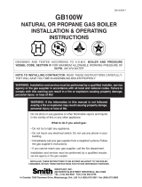
Figure 1 - Clearances to Combustible Construction
The installation must conform to the requirements of the
authority having jurisdiction or, in the absence of such
requirements, to the National Fuel Gas Code, ANSI
Z223.1-latest revision. In Canada, the installation must
be in accordance with the requirements of CSA B149.1
or B149.2 Installation Code for Gas Burning Appliances
and Equipment.
BOILER RATINGS & CAPACITIES
Before undertaking the installation of the GS110 check
the boiler rating plate to ensure that the boiler is the
proper size for the job. The "Net I=B=R Ratings" specify
the equivalent amount of direct cast iron radiation that
the boiler can handle under normal conditions.
Also ensure that the boiler has been set up for the type
of gas available at the installation site. Other important
considerations are the availability of an adequate
electrical supply, fresh air for combustion and proximity
a suitable outside wall.
BOILER LOCATION
WARNING: The clearances to combustible
construction show in Figure 1 must be main-
tained. Failure to comply with this warning can
result in extensive property damage, severe
personal injury or death!
CAUTION: Do not lift the boiler by the jacket. Use a
hand truck under the base frame as shown in Figure 2.
1. Locate the boiler in an area that provides good
access to the unit. Keep in mind that servicing may
require the removal of jacket panels. Accessibility
clearances must take precedence over fire
protection clearances.
2. An optimum site will be level, central to the hot water
piping system, close to an outside wall and have
adequate fresh air for combustion.
3. Ensure that the floor is structurally sound and will
support the weight of the boiler.
NOTE: This boiler is designed for direct placement
on a combustible floor. Never install this boiler on
carpeting!
4. DO NOT install this boiler in a location that would
subject any of the gas ignition components to direct
contact with water or excessive moisture during
operation or servicing.
5. NEVER store objects on or around the boiler.
WARNING: Never store combustible materials,
gasoline or any product containing flammable
vapors or liquids in the vicinity of the boiler.
Failure to comply with this warning can result
in extensive property damage, severe personal
injury or death!
Figure 2 - Moving Boiler

GS110 DIRECT VENT BOILER INSTALLATION AND OPERATION INSTRUCTIONSPage 4
All Combustion Air From Inside The Building
Older houses often have enough “leakage” to provide
an adequate amount of combustion air provided that the
demand for combustion air is not too great, Figure 3.
Homes that are relatively new or “tight” will most likely
require that the combustion be ducted to the boiler from
outside the building. Any home utilizing other gas
burning appliances, a fireplace, wood stove or any type
of exhaust fan must be checked for adequate
combustion air when all of these devices are in
operation at one time.
If the boiler is to be located in an alcove, closet or other
confined space the distances from the boiler and it's
vent system to all-combustible construction must be
equal to or greater than the minimum clearances in
Figure 1. When installed in a closet or confined space
two permanent openings of equal area adjoining another
room or rooms having sufficient volume to meet the
requirements of an unconfined space must be provided,
Figures 4 & 5. Each opening must have a minimum free
area of one square inch per 1000 Btu/hr (2200 mm
2
/
kW) based on the total input rating of all gas utilization
equipment in the confined area. Each opening must be
no less than 100 square inches (64516 mm
2
) in size.
The upper opening must be within 12 inches (305 mm)
of, but not less than 3 inches (76 mm) from, the top of
the enclosure. The bottom opening must be within 12
inches (305 mm) of, but not less than 3 inches (76 mm)
from, the bottom of the enclosure.
All Combustion Air From Outside The Building
When installed in a confined space without the intake
air option two permanent openings communicating
directly with, or by ducts to, the outdoors or spaces that
freely communicate with the outdoors must be present.
The upper opening must be within 12 inches (305 mm)
of, but not less than 3 inches (76 mm) from, the top of
the enclosure. The bottom opening must be within 12
inches (305 mm) of, but not less than 3 inches (76 mm)
from, the bottom of the enclosure.
Where directly communicating with the outdoors or
communicating with the outdoors through vertical ducts,
each opening shall have a minimum free area of 1 in
2
/
4000 Btu/hr (550 mm2/kW) of the total input rating of
all of the equipment in the enclosure.
Where communicating with the outdoors through hori-
zontal ducts, each opening shall have a minimum free
area of 1 in
2
/2000 Btu/hr (1100 mm
2
/kW) of the total
input rating of all of the equipment in the enclosure.
When ducts are used, they must have the same cross-
sectional area as the free area of the opening to which
they connect. Sizing of an outside air duct must be
based on the total input rating of all gas utilization
equipment in the confined space.
COMBUSTION AIR & VENTILATION
WARNING: This boiler must be supplied with
combustion air in accordance with Section 5.3,
Air for Combustion & Ventilation, of the latest
revision of the National Fuel Gas Code, ANSI
Z223.1/NFPA 54 and all applicable local building
codes. Canadian installations must comply with
CSA B149.1 or .2 Installation Code for Gas
Burning Appliances and Equipment, or
applicable provisions of the local building
codes. Failure to provide adequate combustion
air for this boiler/water heater can result in
excessive levels of carbon monoxide which can
result in severe personal injury or death!
To operate properly and safely this boiler requires a
continuous supply of air for combustion. NEVER store
objects on or around the boiler!
CAUTION: Combustion air contaminated with
fluorocarbons or other halogenated compounds
such as cleaning solvents and refrigerants will
result in the formation of acids in the combustion
chamber. These acids will cause premature failure
of the boiler voiding the warranty!
CAUTION: If the boiler is operated while the building
is under construction it MUST be protected from
wood, concrete, sheet rock and other types of dust.
Failure to properly protect the unit from
construction dust will damage the unit voiding the
warranty!
Buildings may require the installation of a fresh air duct
or other means of providing make-up air if the intake
air option isn't used. Any building utilizing other gas
burning appliances, a fireplace, wood stove or any type
of exhaust fan must be checked for adequate
combustion air when all of these devices are in
operation at one time. Sizing of an outside air duct must
be done to meet the requirements of all such devices.
WARNING: Never operate this boiler in an
environment subjected to a negative pressure
unless the air intake is connected to the
outdoors. Failure to comply with this warning
can result in excessive levels of carbon
monoxide causing severe personal injury or
death!

GS110 DIRECT VENT BOILER INSTALLATION AND OPERATION INSTRUCTIONS Page 5
When calculating the free area necessary to meet the
make-up air requirements of the enclosure,
consideration must be given to the blockage effects of
louvers, grills and screens.
Screens must have a minimum mesh size of 1/4"
(6.4mm). If the free area through a louver or grill is not
known ducts should be sized per Table 1.
Table 1 - Combustion Air Duct Sizing
Figure 3 - Horizontal Positive Pressure Venting Using Inside Combustion Air (Cat. III)
Figure 4 - Vertical Negative Pressure Masonry Chimney System Using Inside Combustion Air (Cat. I)
Input Btuh
Wooden
Louvers
Input Btuh
Metal
Louvers
Input Btuh
1/4” Wire
Screen Mesh
FreshAir
Duct Size
36,000
64,000
96,000
128,000
108,000
192,000
288,000
384,000
144,000
256,000
384,000
512,000
3” x 12”
8” x 8”
8” x 12”
8-1/2” x 16”

GS110 DIRECT VENT BOILER INSTALLATION AND OPERATION INSTRUCTIONSPage 6
Intake Air Option - General Guidelines
This configuration provides combustion air directly to the
boiler using a dedicated pipe. Combustion air can be
drawn in horizontally through an outside wall or vertically
through the roof, see Figures 6, 7, 8, 9 & 10.
WARNING: Each boiler must have it's own intake
air system. Common intake air systems are not
to be used! Improper installation can result in
excessive levels of carbon monoxide which can
cause severe personal injury or death!
Single wall galvanized smoke pipe, single wall aluminum
pipe, flexible aluminum pipe, PVC or CPVC pipe can be
used for the intake air pipe. Maximum intake lengths
must not be exceeded per Table 2, larger diameters may
be used on 3,4,and 5 section boilers.
Figure 5 - Vertical Negative Pressure Metal Chimney System and Inside Combustion Air (Cat. I)
Equivalent Intake
Length (see note)
4” Diameter
Equivalent Intake
Length (see note)
3” Diameter
Boiler
Model
Number
65 feet (19.8 m)
65 feet (19.8 m)
65 feet (19.8 m)
* 40 feet (12.2 m)
* 40 feet (12.2 m)
45 feet (13.7 m)
45 feet (13.7 m)
45 feet (13.7 m)
n/a
n/a
GS110-3
GS110-4
GS110-5
GS110-6
GS110-7
Table 2 - Combustion Air System Sizing
* 4" to 3" reducer required.
Note: Subtract 5 feet (1.5 m) for each 90° elbow.

GS110 DIRECT VENT BOILER INSTALLATION AND OPERATION INSTRUCTIONS Page 7
Figure 6 - Vertical Positive Pressure Venting with Outdoor Combustion Air (Cat. III)
All joints in metal intake air systems must be secured
using corrosion resistant fasteners and sealed using a
suitable Silicone caulk. If PVC or CPVC is used, the
joints must be cleaned with a suitable solvent and
connected using a solvent based PVC cement. The
intake air system MUST be supported by the building
structure not the boiler/water heater.
Intake Air Option - Vertical Guidelines
A listed, nonrestrictive intake air cap must be used. The
intake air cap must terminate as shown in Figure 6. The
penetration point in the roof must be properly flashed
and sealed.
Intake Air Optional - Horizontal Guidelines
The maximum equivalent length for the horizontal intake
air pipe is listed in Table 2. The intake air system must
be pitched down, toward the terminal, 1/4" per foot
(21 mm per meter).
If horizontal runs exceed 5 feet (1.5 m) they must be
supported at 3 foot (0.98 m) intervals with overhead
hangers. Figures 7 through 10 show the four horizontal
air intake options. The intake terminations certified for
use the GS110 are listed in Table 5.

GS110 DIRECT VENT BOILER INSTALLATION AND OPERATION INSTRUCTIONSPage 8
Figure 7 - Horizontal Positive Pressure Venting with Outdoor Combustion Air
Figure 8 - Horizontal Positive Pressure Venting with Outdoor Combustion Air
Smith

GS110 DIRECT VENT BOILER INSTALLATION AND OPERATION INSTRUCTIONS Page 9
Figure 9 - Vertical Negative Pressure Masonry Chimney System using Outside Combustion Air (Cat. I)
Figure 10 - Vertical Positive Pressure Venting using Outside Combustion Air (Cat. III)

GS110 DIRECT VENT BOILER INSTALLATION AND OPERATION INSTRUCTIONSPage 10
Certified vent systems are manufactured by the following
companies:
Heat-fab, Inc.
130 Industrial Blvd., Turners Falls, MA 01376
(800) 772-0739.
Z-Flex U.S., Inc.
20 Commerce Park North, Bedford, NH 03110-6911
(800) 654-5600.
Protech Systems Inc.
26 Gansevoort Street, Albany, NY 12202
(518) 463-7284
GENERAL DIRECT VENT INFO
In this configuration the boiler blower is used to push the
flue products to the outdoors while drawing combustion
air from the outdoors. The instructions under the
COMBUSTION AIR & VENTILATION SECTION must be
followed! The vent system must be sized per Table 3.
Table 3 - Positive Pressure Vent System Sizing
* 4" to 3" reducer required
Note: Subtract 5 feet (1.5 m) for each 90° elbow.
HORIZONTAL DIRECT VENT
SYSTEMS
See figures 7 & 8. The vent materials used in horizontal
positive pressure vent systems must be certified to UL
1738 for installations in the United States, ULS636 for
installations in Canada.
Each 90° elbow is equal to 5 linear feet (1.5 m) of pipe.
To maximize the performance of single wall sheet metal
vent systems locate 90° elbows as far from the boiler as
possible and from one another. For best results, horizontal
vent systems should be as short and straight as possible.
The vent system must be both gas tight and watertight.
All seams and joints in metal pipes must be joined and
sealed in accordance with the vent system manufacturer’s
instructions.
When horizontal vent runs exceed 5 feet (1.5m) they must
be supported at 3 foot (0.98 m) intervals with overhead
hangers. The vent system must be pitched down, toward
the vent terminal, 1/4" per foot (21mm per meter). If any
part of a single wall metal vent system passes through
an unheated space it must be insulated with insulation
rated for 400°F. Structural penetrations must be made
using approved thimbles.
Equivalent Vent
Length (see note)
4” Diameter
Equivalent Vent
Length (see note)
3” Diameter
Boiler
Model
Number
*65 feet (19.8 m)
*65 feet (19.8 m)
*65 feet (19.8 m)
40 feet (12.2 m)
40 feet (12.2 m)
45 feet (13.7 m)
45 feet (13.7 m)
45 feet (13.7 m)
n/a
n/a
GS110-3
GS110-4
GS110-5
GS110-6
GS110-7
GENERAL VENTING GUIDELINES
WARNING: The vent installation must be in
accordance with Part 7, Venting of Equipment,
of the National Fuel Gas Code, ANSI Z223.1/
NFPA 54-latest revision or applicable provisions
of the local building codes. Canadian
installations must comply with CSA B149.1 or
.2 Installation Code. Improper venting can result
in excessive levels of carbon monoxide which
can result in severe personal injury or death!
WARNING: Thimbles and fire-stops must be
used where required. A minimum clearance of
6" must be maintained between single wall
metal vents and combustible construction or a
fire resulting in severe personal injury or death
may occur!
WARNING : Each boiler/water heater must have
it's own vent system. Common positive
pressure vent systems are not to be used!
Improper installation can result in excessive
levels of carbon monoxide which can cause
severe personal injury or death!
All vent systems must be fully supported by the building
structure and not by the boiler/water heater.
VENT SYSTEM OPTIONS
The GS110 may be vented the following ways:
1) Direct Vent (Positive Pressure), uses a vent system
certified to UL 1738 for installations in the United States,
ULS636 for installations in Canada. Combustion air is
piped from the outdoors to the blower inlet.
2) Horizontal Vent (Positive Pressure), uses a vent
system certified to UL 1738 for installations in the United
States, ULS636 for installations in Canada. Combustion
air is obtained from the space in which the unit is installed.
3) Vertical Vent (Positive Pressure), uses a vent system
certified to UL 1738 for installations in the United States,
ULS636 for installations in Canada. Combustion air is
piped from the outdoors to the blower inlet or is obtained
from the space in which the unit is installed.
4) Vertical/Chimney Vent (Negative Pressure), uses an
approved metal chimney system or masonry chimney.
Combustion air is obtained from the space in which the
unit is installed or is piped from the outdoors to the blower
inlet.

GS110 DIRECT VENT BOILER INSTALLATION AND OPERATION INSTRUCTIONS Page 11
Horizontal vent systems shall terminate at least 4 feet
(1.3 m) below, 4 feet (1.3 m) horizontally from or 1 foot
(0.23 m) above any door, window or gravity air inlet into
any building. It must not terminate less than 4 feet (1.3
m) horizontally from, and in no case above or below,
unless a 4 feet (1.3 m) horizontal distance is maintained,
from electric meters, gas meters, regulators and relief
equipment and not less than 7 feet (2.3 m) from any
adjacent public walkway. The bottom of the vent
terminal(s) shall be located at least 5 feet (1.5 m) above
the air intake terminal(s). Avoid terminal locations likely
to be affected by winds, snowdrifts, people and pets.
Table 4 - Certified Vent & Intake Terminals
VERTICAL DIRECT VENT SYSTEMS
See Figures 6 & 10. The vent materials used in vertical
positive pressure vent systems must be certified to UL
1738 for installations in the United States, ULS636 for
installations in Canada.
The maximum length for the vertical vent system is
listed in Table 4. Each 90° elbow is equal to 5 linear
feet (1.5 m) of pipe. To maximize the performance of
single wall sheet metal vent systems locate 90° elbows
as far from the boiler as possible and from one another.
If any part of a single wall metal vent system passes
through an unheated space it must be insulated with
insulation rated for 400°F. Structural penetrations must
be made using approved fire-stops.
The vent system must be both gas tight and watertight.
All seams and joints in metal pipes must be joined and
sealed in accordance with the vent system
manufacturer’s instructions.
Vertical vent systems must be terminated with an
approved terminal cap as shown in Figures 6 & 10.
HORIZONTAL VENT
POSITIVE PRESSURE SYSTEMS
See Figure 3. The vent materials used in horizontal
positive pressure vent systems must be certified to UL
1738 for installations in the United States, ULS636 for
installations in Canada.
The maximum vent lengths are listed in Table 3.
Each 90° elbow is equal to 5 linear feet (1.5 m) of pipe.
To maximize the performance of single wall sheet metal
vent systems locate 90° elbows as far from the boiler
as possible and from one another. Horizontal vent
systems should be as short and straight as possible.
When horizontal vent runs exceed 5 feet (1.5 m) they
must be supported at 3 foot (0.98 m) intervals with
overhead hangers. The vent system must be pitched
down, toward the vent terminal, 1/4" per foot (21 mm
per meter). If any part of a single wall metal vent system
passes through an unheated space it must be insulated
with insulation rated for 400°F. Structural penetrations
must be made using approved thimbles.
The vent system must be both gas tight and watertight.
All seams and joints in metal pipes must be joined and
sealed in accordance with the vent system
manufacturer's instructions.
Horizontal vent systems shall terminate at least 4 feet
(1.3 m) below, 4 feet (1.3 m) horizontally from or 1 foot
(0.23 m) above any door, window or gravity air inlet into
any building. It must not terminate less than 4 feet (1.3
m) horizontally from, and in no case above or below,
unless a 4 feet (1.3 m) horizontal distance is maintained,
from electric meters, gas meters, regulators and relief
equipment and not less than 7 feet (2.3 m) from any
adjacent public walkway. The bottom of the vent
terminal(s) shall be located at least 5 feet (1.5 m) above
the air intake terminal(s). Avoid terminal locations likely
to be affected by winds, snowdrifts, people and pets.
Protect building materials and vegetation from
degradation caused by flue gasses.
Table 5- Certified Vent Terminals
Dia. (in.)
3
4
3
4
3
4
3
4
3
4
3
4
3
4
Part No.
300311
300312
300186
300187
300130
300131
300160
300161
7390GC
7490GC
7390TEE
7490TEE
7392GC
7492GC
7314TERM
7414TERM
Company
Protech
Protech
Protech
Protech
Protech
Protech
Protech
Protech
Heat-Fab
Heat-Fab
Heat-Fab
Heat-Fab
Heat-Fab
Heat-Fab
Heat-Fab
Heat-Fab
Description
Te e
Te e
Bird Screen
Bird Screen
45° Elbow
45° Elbow
90° Elbow
90° Elbow
Mitered
Mitered
Te e
Te e
Screen
Screen
90° Elbow
90° Elbow
Dia. (in.)
3
4
3
4
3
4
3
4
3
4
Part No.
300311
300312
300130
300131
300160
300161
7390TEE
7490TEE
7314TERM
7414TERM
Company
Protech
Protech
Protech
Protech
Protech
Protech
Heat-Fab
Heat-Fab
Heat-Fab
Heat-Fab
Description
Te e
Te e
45° Elbow
45° Elbow
90° Elbow
90° Elbow
Tee
Tee
90° Elbow
90° Elbow

GS110 DIRECT VENT BOILER INSTALLATION AND OPERATION INSTRUCTIONSPage 12
VERTICAL VENT
POSITIVE PRESSURE SYSTEMS
See Figure 11. The vent materials used in vertical
positive pressure vent systems must be certified to UL
1738 for installations in the United States, ULS636 for
installations in Canada.
The maximum vent lengths are listed in Table 3.
Each 90° elbow is equal to 5 linear feet (1.5 m) of pipe.
To maximize the performance of single wall sheet metal
vent systems locate 90° elbows as far from the boiler
as possible and from one another. If any part of a single
wall metal vent system passes through an unheated
space it must be insulated with insulation rated for 400
° F. Structural penetrations must be made using
approved fire-stops.
The vent system must be both gas-tight and watertight.
All seams and joints in metal pipes must be joined and
sealed in accordance with the vent system
manufacturer's instructions. Vertical vent systems must
terminate as shown in Figures 6 & 11. An approved
terminal cap must be used.
VERTICAL VENT
NEGATIVE PRESSURE SYSTEMS
See Figures 4, 5 & 9. The GS110 is listed as a Category
I appliance when vented vertically into a metal chimney
system or masonry chimney sized as listed in Table 6.
WARNING: If an appliance using any type of a
mechanical draft system operating under
positive pressure is connected to a chimney
flue, never connect any other appliances to this
flue. Doing so can result in excessive levels of
carbon monoxide which can cause severe
personal injury or death!
Chimney Inspection & Sizing
A thorough inspection of the masonry chimney must be
performed to ensure that the chimney is clean, properly
constructed and properly sized. Exterior masonry
chimneys should not be used unless properly lined to
prevent condensation and draft problems. Table 6 lists
the equivalent breeching and flue sizes required for the
boiler/water heater. When more than one appliance is
connected to the same chimney flue the flue must be
large enough to safely vent the combined output of all
of the appliances.
Table 6 - Equivalent Breeching & Chimney Size
Note: These sizes are based on a 20 foot (6.1m)
chimney height.
inches (mm) inches (mm)
Boiler
Model
3 (7.6)
3 (7.6)
3 (7.6)
4 (10.2)
4 (10.2)
3 (7.6)
4 (10.2)
4 (10.2)
5 (12.7)
5 (12.7)
GS110-3
GS110-4
GS110-5
GS110-6
GS110-7
Intake DiameterVent & Chimney Diameter

GS110 DIRECT VENT BOILER INSTALLATION AND OPERATION INSTRUCTIONS Page 13
Figure 11 - Vertical Positive Pressure Venting (Cat. III)
The vent connector should be sloped up toward the
chimney 1/4" per foot. Ensure that the vent connector
is properly supported and each connection securely
fastened with at least 3 corrosion resistant sheet metal
screws. The termination of the vent pipe must be flush
with the inside of the chimney flue.
CAUTION: The vent connector length must never
exceed 3/4 of the height of the chimney or venting
problems will occur!
Always provide a minimum clearance of 6 inches
between single wall metal vent pipe and any
combustible materials. Type B1 vent may be used,
clearance between it and any combustible material must
be as listed.
WARNING: Failure to maintain minimum
clearances between vent connectors and
combustible materials can result in a fire
causing extensive property damage, severe
personal injury or death!

GS110 DIRECT VENT BOILER INSTALLATION AND OPERATION INSTRUCTIONSPage 14
Dans la mesure du possible, fermer toutes les
portes et les fenêtres du bâtiment et toutes les
portes entre l'espace où les appareils toujours
raccordés du système d'évacuation sont installés et
les autres espaces du bâtiment. Mettre en marche
les sécheuses, tous les appareils non raccordés au
système d'évacuation commun et tous les
ventilateurs d'extraction comme les hottes de
cuisinère et les ventilateurs des salles de bain.
S'assurer que ces ventilateurs fonctionnent à la
vitesse maximale. Ne pas faire fonctionner les
ventilateurs d'été. Fermer les registres des
cheminées.
d) Place in operation the appliance being inspected.
Follow the lighting instructions. Adjust thermostat so
appliance will operate continuously.
Mettre l'appareil inspecté en marche. Suivre les
instructions d'allumage. Régler le thermostat de
façon que l'appareil fonctionne de façon continue.
e) Test for spillage at the draft hood relief opening after
5 minutes of main burner operation. Use the flame
of a match or candle, or smoke from a cigarette,
cigar or pipe.
Faire fonctionner le brûleur principal pendant 5 min
ensuite, déterminer si le coupe-tirage déborde à
l'ouverture de décharge. Utiliser la flamme d'une
allunette ou d'une chandelle ou la fumée d'une
cigarette, d'un cigare ou d'une pipe.
f) After it has been determined that each appliance
remaining connected to the common venting system
properly vents when tested as outlined above, return
doors, windows, exhaust fans, fireplace dampers
and any other gas-burning appliance to their
previous condition of use.
Une fois qu'il a été d éterminé, selon la métode
indiquée ci-dessus, que chaque appareil raccordé
au système d'évacuation est mis à l'air libre de façor
adéquate. Remettre les portes et les fenêtres, les
ventilateurs, les registres de cheminées et les
appareils au gaz à leur position originale.
g)
Any improper operation of the common venting
system should be corrected so the installation
conforms with the National Fuel Gas Code, ANSI
Z223.1/NFPA 54. When resizing any portion of the
common venting system, the common venting system
should be resized to approach the minimum size as
determined using the appropriate tables in Appendix
F in the National Fuel Gas Code, ANSI Z223.1/ NFPA
54 and or CSA B149 Installation Codes.
COMMON VENT SYSTEMS
WARNING: DO NOT connect this boiler or any
other appliance using a positive pressure
common vent system or a mechanical draft
system! Failure to comply with this WARNING
could result in the accumulation of carbon
monoxide gas which can cause severe personal
injury or death!
If an existing boiler/water heater is removed from a
common venting system, the common venting system
may then be too large for the proper venting of the
remaining appliances connected to it. At the time of
removal of an existing boiler/water heater, the following
steps shall be followed with each appliance remaining
connected to the common venting system placed in
operation, while the other appliances remaining
connected to the common venting system are not in
operation.
Au moment du retrait d'une chaudière existante, les
mesures suivantes doivent être prises pour chaque
appareil toujours raccordé au système d'évacuation
commun et qui fonctionne alors que d'autres appareils
toujours raccordés au système d'évacuation ne fonction-
nent pas: système d'évacuation
a) Seal any unused openings in the common venting
system.
Sceller toutes les ouvertures non utilisées du sys-
tème d'évacuation.
b) Visually inspect the venting system for proper size
and horizontal pitch and determine there is no
blockage or restriction, leakage, corrosion and other
deficiencies which could cause an unsafe condition.
Inspecter de façon visuelle le système d'évacu-ation
pour déterminer la grosser et l'inclinaison
horizontale qui conviennent et s'assurer que le
système est exempt d'obstruction, d'étranglement
de fruite, de corrosion et autres défaillances qui
pourraient présenter des risques.
c) Insofar as is practical, close all building doors and
windows and all doors between the space in which
the appliances remaining connected to the common
venting system are located and other spaces of the
building. Turn on clothes dryers and any appliance
not connected to the common venting system. Turn
on any exhaust fans, such as range hoods and
bathroom exhaust, so they will operate at maximum
speed. Do not operate a summer exhaust fan for a
boiler installation. Close fireplace dampers.

GS110 DIRECT VENT BOILER INSTALLATION AND OPERATION INSTRUCTIONS Page 15
WARNING: Failure to connect a condensate trap
or pump to the flue collector can result in
excessive levels of carbon monoxide which can
cause severe personal injury or death!
HEATING SYSTEM PIPING
CAUTION: All heating system piping must be
installed in accordance with the ANSI/ASME Boiler
and Pressure Vessel Code, Section IV. All applicable
local codes and ordinances must also be followed.
If the boiler is installed above any radiation
elements it must be fitted with a low water cutoff
device installed above the normal boiler water level!
The GS110 hot water boiler comes from the factory
ready to be piped to the heating system. Each boiler is
equipped with a safety relief valve which must be piped
in accordance with the ANSI/ASME Boiler and Pressure
Vessel Code, Section IV, see Figure 13.
Table 7 - Boiler Water Volume
* 1-1/2 " Supply and Return Tappings
Figure 13 - Relief Valve Piping
Liters Gallons
Boiler
Model
6.8
9.1
11.4
13.6
15.9
1.8
2.4
3.0
3.6
4.2
GS110-3
GS110-4
GS110-5
GS110-6
GS110-7
Water Volume
Tout mauvais fonctionnement du systéme d'évacu-
tion commun devrait étré corrigé de façor que
l'installation soit conforme au National Fue Gas Code,
ANSI Z223.1/NFPA 54 et (ou) aux codes d'in-
stallation CSA-B149. Si la grosseur d'une section du
système d' évacuation doit étré modifiée, le système
devrait étré modifié pour respecter les valeurs
minimales des tableaux pertinents de l'appendice F
du National Fuel Gas Code, ANSI Z223.1/ NFPA 54
et (ou) des codes d'installation CSA-B149.
CONDENSATE PIPING
A small amount of condensate is generated on start up.
To prevent an excess amount of condensate collecting
in the flue collector a condensate drain has been
provided. A condensate trap or pump MUST be
connected to the condensate fitting in the bottom of the
flue collector.
A trap can be made by tie wrapping a 4” loop in a piece
of vinyl hose attached to the condensate drain fitting.
The trap must be filled with water to prevent flue
gassses from escaping, see Figures 12 A and B.
A condensate hose has been supplied with
boiler and is located inside the literature bag.
Installing contractor will have to continue the
run of condensate to a nearby drain or pump.
Figure 12A- Condensate Trap
Figure 12B- Condensate Trap
SIOM-75

GS110 DIRECT VENT BOILER INSTALLATION AND OPERATION INSTRUCTIONSPage 16
Ensure that the boiler is level from front to back and
from side to side. Use metal shims to level the boiler.
NEVER use combustible materials for shims.
Bypass Piping
CAUTION: Never connect this boiler directly to a
large volume system, in-floor radiant system, snow
melt system or any other system that would cause
the steady state water temperature in the boiler to
drop below 140° F. To prevent damage due to
excessive condensation, one of the following piping
options must be used or the boiler warranty will be
voided!
CAUTION: The blend pump arrangement shown in
Figure 16 must be used when the flow from any
zone in a multiple zone system is less than 4 GPM
or boiler short cycling on the high limit will occur!
For the three systems listed below, adjust the bypass
valve to divert some of the heated water back into the
boiler's return piping. When adjusted correctly the
temperature of the boiler water will exceed 140°F within
five minutes of a warm start. A plug valve should be
used as the bypass valve for best system performance.
NOTE: Some of the circulator's capacity will be used
in the blending process for the first two systems.
Large heating systems may require a larger
circulator.
System Bypass
The system bypass shown in Figure 14 should be used
on single zone systems, or multiple zone systems using
zone valves, when the circulator is installed in the return
piping. The bypass must be installed between the supply
and return pipes on the suction side of the circulator.
Figure 14 - System Bypass Piping
Pump Away Bypass
The system bypass shown in Figure 15 should be used
on single zone systems, or multiple zone systems using
zone valves, when the circulator is installed in the supply
piping. The bypass must be installed between the supply
and return pipes on the pressure side of the circulator.
Figure 15 - Pump Away Bypass Piping
Pumped Blend Bypass
The system bypass shown in Figure 16 should be used
on multiple zone systems. The bypass must be installed
between the supply and return pipes on the suction side
of the zone circulators. The bypass valve must be
installed on the pressure side of the bypass circulator.
Figure 16 - Pumped Bypass Piping

GS110 DIRECT VENT BOILER INSTALLATION AND OPERATION INSTRUCTIONS Page 17
Piping For Use With Cooling Units
The boiler, when used in connection with a refrigera-tion
system must be installed so the chilled medium is piped
in parallel with the boiler. Appropriate valves must be
used to prevent the chilled water from entering the
boiler.
When a boiler is connected to a heating coil that may be
exposed to refrigerated air from an air handling device, the
piping system must be equipped with flow-control valves or
some other automatic means of preventing gravity
circulation of the boiler water during the cooling cycle.
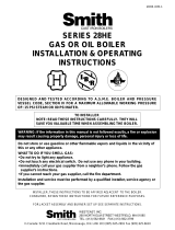
Circulators
The TACO 007 circulator supplied with the boiler is sized
for use in a closed heating system with a 30 psi
maximum operating pressure. If the 007 circulator does
not have the required capacity for the system in which
it is to be installed, an extra zone circulator or a higher
capacity circulator will be needed. Figure 17 depicts the
performance curve for the TACO 007 circulator.
Figure 17 - TACO 007 Performance Curve
10
8
6
4
2
0
0 5 10 15 20 25
FLOW - GPM
HEAD - FEET OF WATER
TACO 007 CIRCULATOR
PERFORMANCE CURVE

GS110 DIRECT VENT BOILER INSTALLATION AND OPERATION INSTRUCTIONSPage 18
GAS SUPPLY PIPING
The GS110 hot water boiler comes from the factory
ready to be piped to the gas supply. The gas supply can
be piped from the left or right side of the boiler.
If for any reason the boiler is not for the type of gas
available at the installation site, call the nearest Smith
Cast Iron Boiler distributor to resolve the problem.
Figure 18 depicts the proper way to connect the boiler
to the gas supply piping. The manual shut-off valve
MUST be installed in the supply piping. It should be
approximately 5 feet above the floor. Provide a sediment
trap/drip leg at the bottom of the vertical section of the
gas supply pipe. A ground joint union should be installed
between the boiler gas controls and the supply piping.
Each of these items is needed to ensure long life and
ease of servicing. Always use a pipe sealant that is
suitable for use with LP gas.
Figure 18 - Gas Supply Piping
CAUTION: Always use a wrench on the gas valve
body when making gas connections to it. Never
over-tighten the piping entering the gas valve body
or the gas valve will be damaged!
Table 8 should be used to ensure that the gas supply
piping is sized properly. If more than one appliance is
supplied by the same supply pipe, the piping must be
sized based on the maximum possible demand. Do not
neglect the pressure drop due to pipe fittings. Table 9
should be used in conjunction with Table 8 to ensure
that the gas supply piping is sized properly.
Safe lighting and other performance criteria were met
with the gas manifold and control assembly provided on
the boiler when the boiler underwent tests specified in
ANSI Z21.13. All gas connections MUST be leak tested
before putting the boiler into operation.
Table 8 - Gas Pipe Capacity
Table 9 - Equivalent Pipe Length Chart
Whenever the gas supply piping is pressure tested the
boiler gas controls must be protected. If the test pres-
sure is equal to, or less than 1/2 psig (3.5 kPa) isolate
the boiler by closing it's manual shut off valve, see
Figure 18. If the test pressure is greater than 1/2 psig
(3.5 kPa), disconnect the boiler and it's individual shut-
off valve from the gas supply piping.
WARNING: Never use an open flame to test for
gas leaks. Always use an approved leak
detection method. Failure to comply with this
WARNING could result in an explosion!
ELECTRICAL WIRING
CAUTION: Label all wires prior to disconnection
when servicing controls. Wiring errors can cause
improper and dangerous operation!
ATTENTION: Au moment de l'entretien des
commandes, étiquetez tous les fils avant de les
débrancher. Des erreurs de câblage peuvent
entraîner un fonctionnement inadéquat et
dangereux. S'assurer que l'appareil fonctionne
adéquatement une fois l'entretirn terminé.
The electrical connections to this boiler/water heater
must be made in accordance with all applicable local
codes and the latest revision of the National Electrical
Code, ANSI /NFPA-70. Installation should also conform
with CSA C22.1 Canadian Electrical Code Part I if
GS110
Section
Size
3
4
5
6
7
Connection
Tapping
1/2"
1/2"
1/2"
3/4"
3/4"
Pipe length in feet
10 20 30 40 50 60 80 100 150
Gas pipe Capacity (ft
3
/hr)
278 190 152 130 115 105 90 79 64
520 350 285 245 215 195 170 150 120
1050 730 590 500 440 400 350 305 250
1600 1100 890 760 670 610 530 460 380
Nominal
Iron Pipe
Size, (in)
3
/4″
1″
1
1
/4″
1
1
/2″
Type of pipe fitting
90° Elbow
Tee Gas Valve
Gas Cock
(branch flow)
(full port)
Equivalent length of pipe fitting in feet
2.6 5.2 0.6 1.5
3.5 6.9 0.8 1.9
4.0 8.0 0.9 2.3
5.2 10.3 1.2 3.0
Nominal
Iron Pipe
Size, (in)
3
/4″
1″
1
1
/4″
1
1
/2″
Note: Maximum pipe capacity in ft
3
/hr is based on a 0.60 specific
gravity gas at a pressure of 0.5 psig and a 0.3" WC pressure drop.

GS110 DIRECT VENT BOILER INSTALLATION AND OPERATION INSTRUCTIONS Page 19
installed in Canada. Install a separate 120 volt 15 amp
circuit for the boiler. A properly rated shut-off switch
should be located at the boiler. The boiler must be
grounded in accordance with the authority having
jurisdiction, or if none, the latest revision of the National
Electrical Code, ANSI/NFPA-70.
Line voltage field wiring of any controls or other devices
must use copper conductors with a minimum size of #14
awg. Low voltage wiring must not be less than #18 awg
with a neoprene, thermoplastic or other equivalent
insulation having a minimum insulation thickness of
0.012 inches.
Refer to Figures 19A and 19B for proper wiring
connections.
Thermostat Installation
ALWAYS follow the instructions included with the ther-
mostat to be used to control the boiler. Proper location
of the thermostat will ensure efficient trouble-free
operation of the boiler. Mount the thermostat to an inside
wall at a height approximately five feet above the floor.
Avoid placing the thermostat in areas that will not pro-
vide an accurate measurement of the room temperature.
Locating the thermostat behind a door, in an alcove,
close to a source of thermal radiation or in a drafty area
will cause poor or sporadic heating.
OPERATIONAL SEQUENCE
The control energizes the circulator motor when the
thermostat contacts are closed. The control then checks
that the limit switch is closed, if not the control will wait
for the limit switch to close. With the limit switch closed
the pressure switch contacts are checked. If the
pressure switch contacts are open the blower motor is
energized. If the pressure switch contacts aren’t open
the control will wait 45 seconds then lock out. The
PURGE light will flash to indicate a pressure switch fault.
Also, if the pressure switch does not close within 5
minutes of the blower being turned on, the control will
lock out with the PURGE light flashing to indicate a
pressure switch fault.
The pre-purge period begins when the pressure switch
contacts close. At the end of the pre-purge period, the
control energizes the HSI igniter for an HSI warm-up
period. This condition will be indicated by illumination of
the IGNITER light. A one second trial for ignition will take
place. In the event ignition is not achieved by the end of
the first trial for ignition period, the control will run through
a post purge and then de-energize the inducer. When
the pressure switch contacts open the control will begin
a new ignition sequence. Failure to establish flame after
the third attempt will result in ignition lock-out and the
VALVE light on the control will flash.
Once the flame has been proven, the system is in
Steady-State heating mode. The control will continuously
monitor the thermostat, limit switch, pressure switch, and
flame sense. If the thermostat opens, the control will
de-energize the gas valve and begin post-purge. If the
limit switch opens, the control will de-energizes the gas
valve, run through post-purge, and wait for the limit
switch to re-close before attempting re-ignition. If flame
is lost, the control will de-energize the gas valve, run
through post-purge, and go to pressure switch proving
mode for re-ignition. If the pressure switch opens for
more than 0.1 seconds the inducer is turned off for 30
seconds, then the control goes to the pressure switch
proving mode for a re-ignition attempt.
When the thermostat is satisfied the post purge period
starts. A post-purge will be performed at any time the
gas valve has been on and is turned off, except for loss
of pressure switch, when a post-purge would be
ineffective. The post-purge must be completed before a
new ignition sequence can start.
In the event that the flame signal is lost after the flame
has been proven, the system will turn off the gas valve
within 2.0 seconds, perform the post-purge, and repeat
the ignition sequence. As a preventative measure to
avoid nuisance shutdown due to a flickering flame, the
flame must be lost for a minimum of 0.5 seconds.
Control Outputs:
Induced draft blower - 1.75 Amps @ 120 VAC.
Circulator Pump - 2.7 Amps @ 120 VAC.
Hot Surface Igniter - 5.0 Amp resistive @ 120 VAC.
Gas Valve - 0.6 Amp @ 24 VAC, 0.45 power factor.

GS110 DIRECT VENT BOILER INSTALLATION AND OPERATION INSTRUCTIONSPage 20
Figure 19A - Wiring Connection Diagram
/