Page is loading ...

Instructions - Parts
Hopper or Hose
Heat Circulation Kit
For circulating heated water or oil through XM and XP plural-component sprayer double
wall hoppers, heated hose, and Viscon
®
HP heater.
Approved for use in explosive atmospheres.
Model 256273 (for XM)
Includes parts needed to assemble heated hose system. Heated hose assembly and Viscon HP heater must be
ordered separately.
Model 24M224 (for XP)
Includes parts needed to assemble heated hose system. Heated hose assembly and Viscon HP heater must be
ordered separately.
See Technical Data on page 26 for Maximum Working Pressure and Temperature Rating information.
Important Safety Instructions
Read all warnings and instructions in this manual.
Save these instructions.
r_256273_313259_1b
Model 256273 (shown installed on XM)
ti19154a
Model 24M224
(shown installed on XP with 20 gallon hoppers)
313259D
EN

Related Manuals
2 313259D
Contents
Related Manuals . . . . . . . . . . . . . . . . . . . . . . . . . . . 2
Warnings . . . . . . . . . . . . . . . . . . . . . . . . . . . . . . . . . 3
Heated Hopper or Hose Circulation Kit 256273 . . 5
Heated Hose Assembly . . . . . . . . . . . . . . . . . . . . 5
Fluid Heater . . . . . . . . . . . . . . . . . . . . . . . . . . . . 6
Typical Installation . . . . . . . . . . . . . . . . . . . . . . . . . 8
Installation . . . . . . . . . . . . . . . . . . . . . . . . . . . . . . . 14
Grounding . . . . . . . . . . . . . . . . . . . . . . . . . . . . . 14
Tubing Lengths . . . . . . . . . . . . . . . . . . . . . . . . . 14
Install . . . . . . . . . . . . . . . . . . . . . . . . . . . . . . . . . 14
Setup . . . . . . . . . . . . . . . . . . . . . . . . . . . . . . . . . 17
Connecting Additional Hose Lengths . . . . . . . . 17
Operation . . . . . . . . . . . . . . . . . . . . . . . . . . . . . . . . 18
Maintenance . . . . . . . . . . . . . . . . . . . . . . . . . . . . . . 19
Troubleshooting . . . . . . . . . . . . . . . . . . . . . . . . . . . 19
Parts . . . . . . . . . . . . . . . . . . . . . . . . . . . . . . . . . . . . 20
Technical Data . . . . . . . . . . . . . . . . . . . . . . . . . . . . 26
Graco Standard Warranty . . . . . . . . . . . . . . . . . . . 28
Graco Information . . . . . . . . . . . . . . . . . . . . . . . . . 28
Related Manuals
Manual Description
312359 XM Operation
313289 XM Repair
313292 XM OEM, Instructions-Parts
3A0420 XP Instructions-Parts
312747 Double Wall Hopper, Instructions-Parts
309524
Viscon
®
HP Heater
308981
Husky
™
716 Diaphragm Pump

Warnings
313259D 3
Warnings
The following warnings are for the setup, use, grounding, maintenance, and repair of this equipment. The exclama-
tion point symbol alerts you to a general warning and the hazard symbol refers to procedure-specific risk. Refer back
to these warnings. Additional, product-specific warnings may be found throughout the body of this manual where
applicable.
WARNINGWARNINGWARNING
WARNING
FIRE AND EXPLOSION HAZARD
Flammable fumes, such as solvent and paint fumes, in work area can ignite or explode. To help prevent
fire and explosion:
• Use equipment only in well ventilated area.
• Eliminate all ignition sources; such as pilot lights, cigarettes, portable electric lamps, and plastic drop
cloths (potential static arc).
• Keep work area free of debris, including solvent, rags and gasoline.
• Do not plug or unplug power cords, or turn power or light switches on or off when flammable fumes
are present.
• Ground all equipment in the work area. See Grounding instructions.
• Use only grounded hoses.
• Hold gun firmly to side of grounded pail when triggering into pail.
• If there is static sparking or you feel a shock, stop operation immediately. Do not use equipment
until you identify and correct the problem.
• Keep a working fire extinguisher in the work area.
EQUIPMENT MISUSE HAZARD
Misuse can cause death or serious injury.
• Do not operate the unit when fatigued or under the influence of drugs or alcohol.
• Do not exceed the maximum working pressure or temperature rating of the lowest rated system
component. See Technical Data in all equipment manuals.
• Use fluids and solvents that are compatible with equipment wetted parts. See Technical Data in all
equipment manuals. Read fluid and solvent manufacturer’s warnings. For complete information
about your material, request MSDS forms from distributor or retailer.
• Check equipment daily. Repair or replace worn or damaged parts immediately with genuine manu-
facturer’s replacement parts only.
• Do not alter or modify equipment.
• Use equipment only for its intended purpose. Call your distributor for information.
• Route hoses and cables away from traffic areas, sharp edges, moving parts, and hot surfaces.
• Do not kink or over bend hoses or use hoses to pull equipment.
• Keep children and animals away from work area.
• Comply with all applicable safety regulations.
ELECTRIC SHOCK HAZARD
Improper grounding, setup, or usage of the system can cause electric shock.
• Turn off and disconnect power cord before servicing equipment.
• Use only grounded electrical outlets.
• Use only 3-wire extension cords.
• Ensure ground prongs are intact on sprayer and extension cords.
• Do not expose to rain. Store indoors.

Warnings
4 313259D
WARNINGWARNINGWARNING
WARNING
SKIN INJECTION HAZARD
High-pressure fluid from gun, hose leaks, or ruptured components will pierce skin. This may look like just
a cut, but it is a serious injury that can result in amputation. Get immediate surgical treatment.
• Do not point gun at anyone or at any part of the body.
• Do not put your hand over the spray tip.
• Do not stop or deflect leaks with your hand, body, glove, or rag.
• Do not spray without tip guard and trigger guard installed.
• Engage trigger lock when not spraying.
• Follow Pressure Relief Procedure in this manual, when you stop spraying and before cleaning,
checking, or servicing equipment.
BURN HAZARD
Equipment surfaces and fluid that’s heated can become very hot during operation. To avoid severe
burns, do not touch hot fluid or equipment. Wait until equipment/fluid has cooled completely.
TOXIC FLUID OR FUMES HAZARD
Toxic fluids or fumes can cause serious injury or death if splashed in the eyes or on skin, inhaled, or
swallowed.
• Read MSDS’s to know the specific hazards of the fluids you are using.
• Store hazardous fluid in approved containers, and dispose of it according to applicable guidelines.
• Always wear impervious gloves when spraying or cleaning equipment.
PERSONAL PROTECTIVE EQUIPMENT
You must wear appropriate protective equipment when operating, servicing, or when in the operating
area of the equipment to help protect you from serious injury, including eye injury, inhalation of toxic
fumes, burns, and hearing loss. This equipment includes but is not limited to:
• Protective eyewear
• Clothing and respirator as recommended by the fluid and solvent manufacturer
•Gloves
• Hearing protection

Heated Hopper or Hose Circulation Kit 256273
313259D 5
Heated Hopper or Hose Circulation Kit 256273
The kit described in this manual; includes all miscellaneous parts needed to assemble the system. There are three
options for using circulation kit 256273:
• Circulate water through the heater and only the hop-
pers. See page 8.
• Circulate water through the heater, hoppers, and
heated hose. See page 10.
• Circulate water through the heater and only the
heated hose. See page 12.
Heated Hose Assembly
Order separately a heated hose assembly that meets maximum pressure and hose diameter requirements. You can
connect up to six 50 ft. (15.2 m) heated hose sections for a maximum total length of 300 ft. (91.4 m). See manual
309525.
Single Hose Assemblies
A B
C D
Dual Hose Assembly
A
B
Single Hose Assembly
Part No.,
Series
Maximum
Pressure Rating
psi (MPa, bar)
Hose Diameter
in. (mm)
Thread A
npt(m)
Thread B
npsm(f)
Approvals
245840, C 5000 psi (34, 345) 1/4 (6.35) 1/4 1/4
245841, C 7250 psi (50, 500) 1/4 (6.35) 1/4 1/4
245842, C 5000 psi (34, 345) 3/8 (9.53) 3/8 3/8
245843, C 7250 psi (50, 500) 3/8 (9.53) 3/8 3/8
245844, C 5000 psi (34, 345) 1/2 (12.7) 1/2 1/2
245845, C 7250 psi (50, 500) 1/2 (12.7) 1/2 1/2
II 2 G

Heated Hopper or Hose Circulation Kit 256273
6 313259D
Dual Hose Assemblies
Fluid Heater
Order separately a VISCON HP heater that meets local electrical and hazardous location requirements.
Hazardous Location Heaters
Non-hazardous Location Heaters
Part No.,
Series
Maximum
Pressure Rating
psi (MPa, bar)
Hose Diameter
in. (mm)
Thread
A
npt(m)
Thread
B
npsm(f)
Thread
C
npt(m)
Thread
D
npsm(f)
Approvals
248118, C 7250 psi (50, 500) 1/2 (12.7) 1/2 1/2 1/2 1/2
248119, C 7250 psi (50, 500) 3/8 (9.53) 3/8 3/8 3/8 3/8
248120, C 7250 psi (50, 500) A = 1/2 (12.7)
B = 3/8 (9.53)
1/2 1/2 3/8 3/8
248121, C 7250 psi (50, 500) A = 3/8 (9.53)
B = 1/4 (6.35)
3/8 3/8 1/4 1/4
24M439, C 7250 psi (50, 500) A = 1/2 (12.7)
B = 1/4 (6.35)
1/2 1/2 1/4 1/4
24M440, C 5000 psi (34, 345) A = 3/8 (9.53)
B = 1/4 (6.35)
3/8 3/8 1/4 1/4
24M441, C 5000 psi (34, 345) 3/8 (9.53) 3/8 3/8 3/8 3/8
24M442, C 5000 psi (34, 345) A = 1/2 (12.7)
B = 1/4 (6.35)
1/2 1/2 1/4 1/4
24M443, C 5000 psi (34, 345) A = 1/2 (12.7)
B = 3/8 (9.53)
1/2 1/2 3/8 3/8
24M444, C 5000 psi (34, 345) 1/2 (12.7) 1/2 1/2 1/2 1/2
Part No.
Series
VAC (50/60 Hz single phase) / Watts / Amps
Approvals
245848 A 120 / 2300 / 19.2
See heater manual 309524 for approvals.
245863 A 240 / 4000 / 16.7
245864 A 480 / 4000 / 8.30
245862 A 200 / 4000 / 20.0
246254 A 380 / 4000 / 10.5
II 2 G
Model No.
Series
VAC (50/60 Hz single phase) / Watts / Amps
Approvals
245867 A 120 / 2300 / 19.2
See heater manual 309524 for approvals.
245868 A 200 / 4000 / 20.0
245869 A 240 / 4000 / 16.7
245870 A 480 / 4000 / 8.30
246276 A 380 / 4000 / 10.5

Heated Hopper or Hose Circulation Kit 256273
313259D 7

Typical Installation
8 313259D
Typical Installation
NOTE: XM kit 256273 is shown in all typical installation illustrations. The general layout for XP Kit 24M224 is the
same.
Key:
A Viscon HP Heater
B Husky diaphragm pump
C Hopper
DFrame
E Fluid circulation tubing
NOTE:
See F
IG. 2 on page 9 for fluid schematic of heated fluid.
F
IG. 1: Heat Only Hoppers Configuration
C
A
C
B
E
E
E
D
r_256273_313259_1b

Typical Installation
313259D 9
FIG. 2: Fluid schematic for only heating hoppers
Back-Mounted Hoppers (BM)
Side-Mounted Hoppers (SM)
Table 1: Tubing Lengths
Section Tubing
(BM) Hoppers
in (mm)
(SM) Hoppers
in (mm)
AA 1/2 in. 65 (1651) 50 (1270)
AB 51 (1295.4) 35 (889)
AC 7 (177.8) 4 (101.6)
BA 3/4 in. 40 (1016) 36 (914.4)
BB 29 (736.6) 17 (431.8)
BC 7 (177.8) 7 (177.8)
CA 3/8 in. 21 (533.4) 21 (533.4)
CA
AB
AA
BA
BA
AC
BC
AA
AB
AC
BC
CA
BA
BB

Typical Installation
10 313259D
Key:
A Viscon HP Heater
B Husky diaphragm pump
C Hopper
DFrame
E Fluid circulation tubing
F Heated hose tee and elbow fittings (see heated hose
connections on page F
IG. 5 and FIG. 6 on page 12 and
13.)
NOTE:
See F
IG. 6 on page 13 for fluid schematic of heated fluid.
F
IG. 3: Hoppers and Heated Hose Configuration
C
A
C
B
D
E
E
E
E
F
ti19227a


Typical Installation
12 313259D
Key:
A Viscon HP heater
B Husky diaphragm pump
C Hopper (not shown)
DFrame
E Fluid circulation tubing
F Heated hose tee and elbow fitting (to red tubing)
G Return hose tee and elbow fitting (from blue tubing)
H Recirculation valve
J Heated hose assembly (purchase separately)
K Overflow tank (used for only heated hose configuration)
NOTE:
See F
IG. 6 on page 13 for fluid schematic of heated fluid.
F
IG. 5: Heated Hose Only Configuration
A
B
D
E
G
F
J
K
H
H
F
G
G
F
r_256273_313259_13a
Heated Water Fluid Flow

Typical Installation
313259D 13
FIG. 6: Fluid schematic for heated hose
RED
BLUE
G
F
Single Hose Shown
23 in.
(584.2 mm)
38 in.
(965.2 mm)
24 in.
(609.6 mm)

Installation
14 313259D
Installation
Grounding
The equipment must be grounded. Grounding reduces
the risk of static and electric shock by providing an
escape wire for the electrical current due to static build
up or in the event of a short circuit.
1. Remove grounding screw on diaphragm pump (3)
and tighten ring terminal on grounding cable (15)
under ground screw.
2. Loosen grounding lug locknut (W) on back of control
box. Insert ground wire end (Y) into lug slot and
tighten locknut securely.
Tubing Lengths
The length of tubing (4, 16, 29) is determined by the
hopper mounting configuration and heating choices.
Reference the fluid schematic, from the configurations
listed below, to find the tubing lengths.
• Heating hoppers only. See F
IG. 2 on page 9.
• Heating hoses only. See F
IG. 6 on page 13.
• Heating hoppers and hoses. See F
IG. 4 on page 11.
Cut tubing to length specified in fluid schematics.
1. Use tubing cutter to cut tubing (4) squarely to
desired lengths.
NOTE: To ensure a leak-proof seal, apply PTFE tape
on all npt threads.
2. Insert tubing through the back of the nut in each of
the plastic fittings (7) until the tube stops. Tighten
the nut hand tight, then tighten it to 1-1/2 to 2 turns
with a wrench.
Install
1. XM Kit 256273 only: Mount bracket (1) on XM
frame (D) using screws (5).
2. XP Kit 24M224 only: Mount brackets (101, 102) on
XP frame (D) using plates (105), screws (134),
nuts (133).
15
Y
r_256273_313259_9
Y
W
r_256273_313259_10
5
1
D
r_256273_313259_5
102
101
D
105
134
133
133
134
105
ti19176a

Installation
313259D 15
3. XM Kit 256273 only: Remove 3/4 npt plugs from
the end of the diaphragm pump fluid manifold and
place in center.
4. For only heating hoppers or heating hoppers
and heated hose: Install tube fitting (31) in fluid
inlet. See F
IG. 7.
5. For heating heated hose only (see F
IG. 7):
a. Install elbow (32), mounting fitting (23), o-ring
(22) and 1.5 gallon reservoir tank (21) on dia-
phragm pump fluid inlet.
b. XM Kit 256273 only: Connect elbow fitting (7)
to mounting fitting (23).
6. Install bushing (12) and elbow tube fitting (17) to
diaphragm pump fluid outlet. See F
IG. 7.
7. Mount diaphragm pump to bracket.
XM Kit 256273 only: Use four screws (2) to mount
pump (3) on mounting bracket. See F
IG. 7.
XP Kit 24M224 only: Use nuts (135) to mount
pump (3) to threads on mounting bracket. See F
IG.
7.
8. Connect air regulator assembly.
XM Kit 256273 only: Connect nipple (10), air regu-
lator/gauge (9), and fitting (19) to pump (3). See F
IG.
7.
XP Kit 24M224 only: Connect elbow (137),
nipple (10), air regulator/gauge (9), elbow (136),
and fitting (19) to pump (3).
9. Remove plug on system air control supply and con-
nect fitting (19) in place of the plug. Connect hose
(27) between fitting (19) on 100 psi (0.7 MPa, 7 bar)
XM air supply and fitting (19) on the air regula-
tor/gauge (9). See F
IG. 7. Refer to Husky 716 man-
ual 308981 if needed.
NOTE: The air regulator (9) controls pump pressure.
F
IG. 7: Diaphragm Pump Installation
9
12
17
31
10
19
3
2
21
32
23
7
12
17
9
10
19
22
3
XM: Heated Hose Only XM: All Others
XP: All OthersXP: Heated Hose Only
31
9
136,19,27
137 10
12
17
134
105
133
ti19173a
ti19155a
21
22
23
7
32
910
136,19,27
137
12
17
134
105
133
33
135
135
33
ti19229a

Installation
16 313259D
10. Slide Viscon HP heater (A) into slots on frame.
Tighten bolts to secure to frame.
11. For heating hoppers or heating hoppers and
heated hose: install fitting (18) and elbow (17) in
the heater’s fluid inlet facing away from the system.
Install elbow (7) in heater outlet facing the back of
the system.
12. For heating heated hose only: connect elbow fit-
ting (17) to heater fluid inlet facing the back of the
system. Install elbow (7) in the heater outlet facing
upward.
13. Wire Viscon HP heater (B) to your voltage supply.
Follow wiring procedure in the Viscon HP manual
309524.
14. If heating hoppers:
a. Remove bottom plug (P) from hopper (C).
b. XP Kit 24M224 only: Install nipple (33) and
coupling (139) into bottom of hopper. See
page 24.
c. Install elbows (32) and fittings (31).
d. Repeat for second hopper.
15. Remove side plug (P) used for fluid inlet.
16. Replace plug with bushing (11) and elbow fitting (7).
17. Cut tubing (4, 16, 29). See Tubing Lengths on
page 14.
NOTE:
Fitting nuts may need retightening as the system
reaches normal operating temperatures.
F
IG. 8
F
IG. 9
A
r_256273_313259_7
XM Kit 256273 XP Kit 24M224
ti19156a
A
r_256273_313259_16a
18
17
7
r_256273_313259_17a
17
All wiring must be done by a qualified electrician. See
warnings, page 3.
P
P
711
32
C
r_256273_313259_8
31
XM shown

Installation
313259D 17
Setup
For heating hoppers only:
See fluid schematic on page 9 and parts on page 21.
NOTE: To ensure a leak-proof seal, use PTFE tape
on all pipe thread connections.
1. Connect A and B fluid hoses to shutoff check valve
outlets (H).
2. Connect elbow fitting (17) in pump outlet (3) and
elbow fitting (17) on heater inlet (A) with tubing (16).
3. Connect fitting (7) in the heater fluid outlet (A) and
tee fitting (13) with tubing (4). Connect tee
fitting (13) and fittings (7) in the hopper side ports
with tubing (4).
4. Connect fittings (31) to elbow in bottom outlet of
hoppers and tee fitting (30) with tubing (29). Con-
nect tee fitting (30) and the pump (3) inlet fitting (31)
with tubing (29).
For heating heated hose only:
See fluid schematic on page 13 and parts on page 22.
1. Connect A and B fluid hoses to shutoff check valve
fluid outlets (H).
2. Connect elbow fitting (17) in pump outlet (3) and
elbow fitting (17) on heater inlet (A) with tubing (16).
3. Connect fitting (7) in the heater fluid outlet (A) and
tee fitting (13) with tubing (4).
4. Connect tee fitting (42) and elbow fitting (41) to
recirculation inlets and outlet connections of the
heated hose. See F
IG. 10.
5. Connect elbow fitting (7) to 1-1/2 gallon tank mani-
fold (23) with tubing (4).
For heating hoppers and heated hose:
See fluid schematic on page 11 and parts on page 20.
1. Connect A and B fluid hoses to shutoff check valve
outlets (H).
2. Connect elbow fitting (17) in pump outlet (3) and
elbow fitting (17) on heater inlet (A) with tubing (16).
3. Connect fitting (7) in the heater fluid outlet (A) and
tee fitting (13) to hose circulation inlet with
tubing (4).
4. Connect tee fitting (13) from hose circulation return
to tee fitting (13) with tubing (4).
5. Connect tee fitting (13) and fittings (7) in the hopper
side ports with tubing (4).
6. Connect fittings (31) to elbow in bottom outlet of
hoppers and tee fitting (30) with tubing (29). Con-
nect tee fitting (30) and the pump (3) inlet fitting (31)
with tubing (29).
Connecting Additional Hose
Lengths
Up to six 50 ft (15.2 m) sections of heated hose can be
attached for a maximum total length of 300 ft (91.4 m).
1. Remove plastic u-turn fittings at the end of the
heated hose assembly.
2. Connect the next length of hose, using union fittings
supplied with the hose.
3. Tubes are color coded. Connect like colors.
F
IG. 10: Recirculation Inlet and Outlet Connections
NOTICE
To prevent cross-contamination, ensure you connect
“A” side fluid hose to “A” side fluid hose on additional
heated hose.
Hopper Inlet or
1-1/2 gallon tank
manifold
Heater Outlet
ti19230a
Blue hose connections
Red hose connections

Operation
18 313259D
Operation
1. Select fluid to use for heating circulation.
• 50% water and 50% ethylene glycol mixture is
recommended for fastest heat-up time and pre-
vention of algae build-up regardless of ambient
temperature.
• Oil can be used but heat-up time will increase
and the hopper fill level must be decreased. See
item 2.
NOTE:
Detailed diaphragm pump operating instructions are in
the Husky 716 diaphragm pump manual 308981.
2. Fill Heating Fluid in double wall hopper (C) outer
cavity. See manual 312747 for instructions.
NOTE:
If using heated hose: each 50 ft. (15.2 m) heated
hose section holds approximately 1.25 gal. (4.7
liters) of fluid.
3. Set the flow rate of the circulation fluid by adjusting
the pump’s air regulator (9) until the pump cycles
about 50 cycles/min. Do not use a higher flow rate
as doing so will decrease system heating perfor-
mance and pump life. Never exceed the hose’s
95 psi (0.6 MPa, 6.6 bar) maximum working pres-
sure rating.
4. Adjust the heater thermostat to the desired circula-
tion temperature. The setting at the heater output
thermometer should be about 10° F (6° C) higher
than the desired paint temperature. Never exceed
the hose’s 140° F (60° C) maximum temperature
rating.See Viscon HP heater manual 309524 for
instructions.
NOTE:
If the hose is not being used for more than one hour,
shut off Viscon HP heater and pump to lengthen heater
life.
NOTICE
Do not plug top ports. Always have venting fittings
installed to prevent outer cavity pressurization.
Failure to do so may cause leakage into spray
material.
NOTICE
If oil is the heating fluid selected, the maximum oil
level must be 3 in. (76.2 mm) below the hopper
side port level. A higher fluid level may cause the
oil to overflow during initial pump and heater
startup.

Maintenance
313259D 19
Maintenance
• Check double wall hopper heating fluid level
monthly. Add fluid as needed.
• Do not overfill when using oil. See overfilling
notice on page 18.
• Follow pump maintenance instructions in Husky 716
diaphragm pump manual 308981.
• Follow heater maintenance instructions in Viscon
HP manual 309524.
Troubleshooting
Problem Cause Solution
Fluid fittings leaking. Loose fittings. Tighten fittings after system reaches
desired temperature.
Hose not heating to desired tempera-
ture.
Diaphragm flow rate set too high. Decrease diaphragm pump flow rate
to 50 cycles/min.
Problem with Viscon HP heater. See troubleshooting in Viscon HP
heater manual 309524.
Diaphragm pump not operating cor-
rectly.
See troubleshooting in Husky 716
diaphragm pump manual 308981.
Oil overflowing out vented hopper
side fill port during startup.
Oil level higher than 3 in. (76.2 mm)
below fill port at room temperature
and at rest.
Lower oil level to 3 in. (76.2) below
hopper fill port.
Hopper not reaching set temperature
when heating fluid hose first.
Temperature loss in heated hose is
too much for the heater capacity to
compensate for.
Allow longer heating time. Insulate
heated hose bundle.
Air and heating fluid splatter is exiting
hopper vented fitting.
Diaphragm in Husky 716 diaphragm
pump is cracked.
Replace pump diaphragm. See man-
ual 308981 for parts.

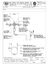
Parts
20 313259D
Parts
256273, XM Heated Hopper or Hose Circulation Kit
For heating hoppers and heated hose
To Re d Tubing
To Blue Tubing
7, 11
7, 11
13
41, 42 41, 42
32, 31
32, 31
30
4
4
16
29
29
4
4
Cut tubing to length. See table on page 9.
See Heater and Diaphragm Pump (3) Connections on page 22.
1
2
1
2
1
1
1
1
1
1
1
29
1
ti19231a
/