
308645
Rev. D
INSTRUCTIONS-PARTS LIST
INSTRUCTIONS
This manual contains important
warnings and information.
READ AND KEEP FOR REFERENCE.
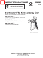
Contractor FTx Airless Spray Gun
3600 psi (252 bar) MAXIMUM WORKING PRESSURE
Model 238350, Series A
Includes RACr DripLesst Guard, 515 size
SwitchTipt, and 4-finger trigger.
Model 824004, Series A
Includes RACr DripLesst Guard, 515 size
SwitchTipt, and 4-finger trigger.
Model 239045, Series A
Includes Flat Tip Guard and 4-finger trigger.
GRACO INC. P.O. BOX 1441 MINNEAPOLIS, MN 55440–1441
ECOPYRIGHT 1996, GRACO INC.
Graco Inc. is registered to I.S. EN ISO 9001
Models 238350, 824004
05963

2 308645
Table of Contents
Warnings 2. . . . . . . . . . . . . . . . . . . . . . . . . . . . . . . . . . . . . .
Installation/Operation 5. . . . . . . . . . . . . . . . . . . . . . . . . . .
System Requirements 5. . . . . . . . . . . . . . . . . . . . . . . . . .
How to Use the Trigger Safety Latch 5. . . . . . . . . . . . .
How to Use the Gun 6. . . . . . . . . . . . . . . . . . . . . . . . . . .
How to Adjust the Spray Pattern 6. . . . . . . . . . . . . . . . . .
How to Clean the Spray Tip
and Clear a Spray Tip Obstruction 7. . . . . . . . . . . .
How to Clean the Filter 8. . . . . . . . . . . . . . . . . . . . . . . . . .
Service 9. . . . . . . . . . . . . . . . . . . . . . . . . . . . . . . . . . . . . . .
Parts Drawing 12. . . . . . . . . . . . . . . . . . . . . . . . . . . . . . . . .
Parts List 13. . . . . . . . . . . . . . . . . . . . . . . . . . . . . . . . . . . . .
Technical Data 15. . . . . . . . . . . . . . . . . . . . . . . . . . . . . . . .
Graco Phone Number 15. . . . . . . . . . . . . . . . . . . . . . . . . .
Graco Warranty 16. . . . . . . . . . . . . . . . . . . . . . . . . . . . . . .
Symbols
Warning Symbol
WARNING
This symbol alerts you to the possibility of serious
injury or death if you do not follow the instructions.
Caution Symbol
CAUTION
This symbol alerts you to the possibility of damage to
or destruction of equipment if you do not follow the
instructions.
WARNING
INSTRUCTIONS
EQUIPMENT MISUSE HAZARD
Equipment misuse can cause the equipment to rupture or malfunction and result in serious injury.
D This equipment is for professional use only.
D Read all instruction manuals, tags, and labels before operating the equipment.
D Use the equipment only for its intended purpose. If you are not sure, call your Graco distributor.
D Do not alter or modify this equipment.
D Check equipment daily. Repair or replace worn or damaged parts immediately.
D Do not exceed the maximum working pressure of the lowest rated system component. Refer to the
Technical Data on page 15 for the maximum working pressure of this equipment.
D Use fluids and solvents which are compatible with the equipment wetted parts. Refer to the Tech-
nical Data section of all equipment manuals. Read the fluid and solvent manufacturer’s warnings.
D Do not use 1,1,1–trichloroethane, methylene chloride, other halogenated hydrocarbon solvents or
fluids containing such solvents in pressurized aluminum equipment. Such use could result in a
chemical reaction, with the possibility of explosion.
D Do not use hoses to pull equipment.
D Route hoses away from traffic areas, sharp edges, moving parts, and hot surfaces. Do not expose
Graco hoses to temperatures above 66_C (150_F) or below –40_C (–40_F).
D Wear hearing protection when operating this equipment.
D Do not lift pressurized equipment.
D Comply with all applicable local, state, and national fire, electrical, and safety regulations.

308645 3
WARNING
INJECTION HAZARD
Spray from the gun, leaks or ruptured components can inject fluid into your body and cause extremely
serious injury, including the need for amputation. Fluid splashed in the eyes or on the skin can also
cause serious injury.
D Fluid injected into the skin might look like just a cut, but it is a serious injury. Get immediate medi-
cal attention.
D Do not point the gun at anyone or at any part of the body.
D Do not put your hand or fingers over the spray tip.
D Do not stop or deflect leaks with your hand, body, glove or rag.
D Do not “blow back” fluid; this is not an air spray system.
D Always have the tip guard and the trigger guard on the gun when spraying.
D Check the gun diffuser operation weekly. See page 8.
D Be sure the gun trigger safety operates before spraying.
D Lock the gun trigger safety when you stop spraying.
D Follow the Pressure Relief Procedure on page 5 if the spray tip clogs and before cleaning,
checking or servicing the equipment.
D Tighten all fluid connections before operating the equipment.
D Check the hoses, tubes, and couplings daily. Replace worn or damaged parts immediately.
Do not repair high pressure couplings; you must replace the entire hose.
D Fluid hoses must have spring guards on both ends, to help protect them from rupture caused by
kinks or bends near the couplings.
MOVING PARTS HAZARD
Moving parts can pinch or amputate your fingers.
D Keep clear of all moving parts when starting or operating the pump.
D Before servicing the equipment, follow the Pressure Relief Procedure on page 5 to prevent the
equipment from starting unexpectedly.
RECOIL HAZARD
Due to the high pressure fluid emitted, a strong recoil action may occur when you trigger this gun. If
you are unprepared, your hand could be forced back toward your body or you could lose your balance
and fall, resulting in serious injury.

4 308645
WARNING
FIRE AND EXPLOSION HAZARD
Improper grounding, poor ventilation, open flames or sparks can cause a hazardous condition and
result in a fire or explosion and serious injury.
D If there is any static sparking or you feel an electric shock while using this equipment, stop spray-
ing immediately. Do not use the equipment until you identify and correct the problem.
D Provide fresh air ventilation to avoid the buildup of flammable fumes from solvents or the fluid
being sprayed.
D Keep the spray area free of debris, including solvent, rags, and gasoline.
D Electrically disconnect all equipment in the spray area.
D Extinguish all open flames or pilot lights in the spray area.
D Do not smoke in the spray area.
D Do not turn on or off any light switch in the spray area while operating or if fumes are present.
D Do not operate a gasoline engine in the spray area.
D Ground the equipment and the object being sprayed. Refer to your pump instruction manual.
TOXIC FLUID HAZARD
Hazardous fluid or toxic fumes can cause serious injury or death if splashed in the eyes or on the skin,
inhaled, or swallowed.
D Know the specific hazards of the fluid you are using.
D Store hazardous fluid in an approved container. Dispose of hazardous fluid according to all local,
state and national guidelines.
D Always wear protective eyewear, gloves, clothing and respirator as recommended by the fluid and
solvent manufacturer.

308645 5
Installation/Operation
System Requirements
WARNING
Keep the wallet-sized warning card provided with
this gun with the operator at all times. The card
contains important treatment information should an
injection injury occur. Additional cards are available
at no charge from Graco Inc.
WARNING
Be sure your system has a bleed-type master air
valve (pneumatic pumps only) and a pressure drain
valve. These accessories help reduce the risk of
serious bodily injury, including fluid injection,
splashing in the eyes or on the skin, or injury from
moving parts, if you are adjusting or repairing the
pump or gun.
1. The bleed-type master air valve (air-powered
pumps only) relieves air trapped between this
valve and the pump after the air regulator is shut
off. Trapped air can cause the pump to cycle
unexpectedly.
2. The pressure drain valve assists in relieving fluid
pressure in the displacement pump, hose and gun:
triggering the gun to relieve pressure may not be
sufficient.
3. Strain the fluid you are spraying if it contains
particles which could clog the spray tip.
Grounding
To reduce the risk of static sparking, ground the spray-
er and all other spray equipment used or located in the
spray area. Check your local electrical code for de-
tailed grounding instructions for your area and type of
equipment.
WARNING
INJECTION HAZARD
The system pressure must be manually
relieved to prevent the system from
starting or spraying accidentally. Fluid
under high pressure can be injected through the
skin and cause serious injury. To reduce the risk of
an injury from injection, splashing fluid, or moving
parts, follow the Pressure Relief Procedure
whenever you:
D are instructed to relieve the pressure,
D stop spraying,
D check or service any of the system equipment,
D or install or clean the spray tip.
Pressure Relief Procedure
1. Engage the gun safety latch.
2. Turn the ON/OFF switch to OFF.
3. Unplug the power supply cord.
4. Disengage the gun safety latch. Hold a metal part
of the gun firmly to a grounded metal pail. Trigger
the gun to relieve pressure.
5. Engage the gun safety latch.
6. Open the system pressure drain valve. Leave the
pressure drain valve open until you are ready to
spray again.
If you suspect that the spray tip or hose is completely
clogged, or that pressure has not been fully relieved
after following the steps above, VERY SLOWLY loos-
en the tip guard retaining nut or hose end coupling to
relieve pressure gradually, then loosen completely.
Now clear the tip or hose obstruction.
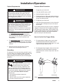
How to Use the Gun Trigger Safety
1. To engage the gun trigger safety, turn the latch
counterclockwise toward the handle until the
detent of the latch locks on and the pin is at a right
angle with the gun body. See Fig. 1.
2. To disengage the gun trigger safety, turn the latch
clockwise away from the handle to unlock the
detent of the latch and turn the pin 180_ from the
gun body.
Fig. 1
ENGAGED DISENGAGED
05964
PIN
LATCH

6 308645
Installation/Operation
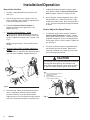
How to Use the Gun
1. Connect a grounded fluid hose to the gun inlet.
See Fig. 2
2. With no tip installed, start the pump. Flush the
pump according to the instructions supplied with it.
Prime the system with the fluid.
3. Follow the Pressure Relief Procedure on
page 5. Be sure the gun trigger safety is en-
gaged. See Fig. 1.
4. Graco Flat Tip Style Driplesst Guard
Install the tip (A) and the gasket (B) in the nut of
the tip guard (C). Screw the assembly firmly onto
the gun. Tighten the assembly with a wrench. See
Fig. 2.
NOTE: If the gasket (B) is not installed, the gun
will leak.
5. Reverse-A-Clean (RAC) IV Models 238350 and
824004
Install the RAC IV SwitchTip (40) and the tip guard
(41). See manual 308644, supplied. See Fig. 2.
Fig. 2
41
C
A
B
05965
40
6. Start the pump. Adjust the fluid pressure until the
spray is completely atomized. Use the lowest
pressure necessary to get the desired results.
Higher pressure may not improve the spray pattern
and will cause premature tip wear and pump wear.
7. If adjusting the pressure does not give a good
spray pattern, follow the Pressure Relief Proce-
dure on page 5 and then try another tip size.
8. Use a full-open, full-close triggering action. Hold
the gun about 12 in. (350 mm) from and at right
angles to the work surface. Don’t swing the gun in
an arc. Practice to find the best length and speed
of stroke.
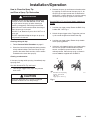
How to Adjust the Spray Pattern
1. To adjust the spray pattern direction, follow the
Pressure Relief Procedure on page 5. Loosen
the tip guard retaining nut (B). Turn the tip guard/
tip groove horizontally (C) for a horizontal pattern
and vertically (A) for a vertical pattern. Tighten the
nut. See Fig. 3.
2. The spray tip orifice and spray angle determines
the coverage and size of pattern. When more
coverage is needed, use a larger spray tip rather
than increasing fluid pressure.
CAUTION
The openings in the tip guard reduce paint buildup on
the tip guard while spraying. Any damage to the
sharp edges of the openings causes paint to collect
at that area. Never hang the gun by the tip guard.
Fig. 3
KEY
A Tip guard shown in position for
vertical spray pattern
B Retaining nut
C Tip guard shown in position for
horizontal spray pattern
A
B
C
A
05971

308645 7
Installation/Operation
How to Clean the Spray Tip
and Clear a Spray Tip Obstruction
WARNING
To reduce the risk of fluid injection or splashing in
the eyes or on the skin, do not hold a hand, body
or rag in front of the spray tip when cleaning or
checking a clogged tip. Point the gun toward the
ground or into a waste container when checking to
see if the spray tip is cleared.
DO NOT try to “blow back” paint; this is NOT an air
spray gun.
DO NOT wipe fluid buildup off the gun or spray tip
until pressure is relieved.
Cleaning during the day.
1. Follow Pressure Relief Procedure on page 5.
2. Clean the front of the tip frequently during the day
to help reduce buildup. Also clean the tip and tip
guard at the end of each work day. Use a solvent-
soaked brush to clean the spray tip.
Clearing an obstruction.
If the spray tip clogs while spraying, immediately stop
spraying, then:
Gun with Standard Flat Tip and Guard
1. Lock the gun trigger safety, open the pressure
drain valve.
CAUTION
Never soak the entire gun in solvent. Prolonged
exposure to solvent can ruin the packings.
2. Remove the spray tip and blow out the obstruction
by applying air to the front of the spray tip. Or, let
the spray tip and gun nozzle soak to dissolve the
obstruction. If it won’t dissolve, jar it out by tapping
the back of the spray tip against a flat surface.
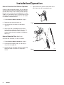
Gun with RAC IV Tip and Guard; Models 238350 and
824004
1. Lock the gun trigger safety. Rotate the RAC IV tip
handle 180_. See Fig. 4.
2. Unlock the gun trigger safety. Trigger the gun into
a pail or onto the ground to remove the clog.
3. Lock the gun trigger safety. Rotate the tip handle
to the spraying position.
4. If the tip is still clogged, lock the gun trigger safety,
shut off the sprayer and disconnect the power
source, and open the pressure drain valve to
relieve pressure. Clean the spray tip as shown in
manual 308644, supplied with the RAC IV.
Fig. 4
KEY
A Handle shown in spraying
position. Turn handle
180_ and
trigger gun to clear clog.
A
05966

8 308645
Installation/Operation
How to Check the Gun Diffuser Operation
Check the diffuser operation weekly. The gun diffuser/
seat (A) breaks up spray and reduces the risk of fluid
injection when the tip is not installed. Perform the test
below. If it fails, replace the entire Needle Kit, Part No.
218070, as instructed on page 7. Diffuser/seats are not
sold separately since the gun will leak if an old needle
is used with a new diffuser/seat.
1. Follow Pressure Relief Procedure on page 5.
2. Remove the tip guard and spray tip.
3. Start the sprayer and adjust it to the lowest
pressure.
4. Aim the gun into a grounded metal pail while
holding it firmly to the pail. Trigger the gun. If the
fluid emitted is not diffused into an irregular
stream, replace the entire needle kit immediately.
See Fig. 5.
How to Clean the Filter (See Fig. 6.)
Clean the filter assembly (17) daily, as follows:
1. Follow Pressure Relief Procedure on page 5.
2. Push up on the trigger guard (12) and swing it
away from the trigger (5).
3. Unscrew the gun handle (6) from the housing (26).
Remove the filter and clean it in compatible
solvent.
4. Apply lithium-base grease to the threads of the
gun handle (14) and reassemble the gun.
Fig. 5
A
05967
Fig. 6
6
12
5
26
05968

308645 9
Installation/Operation
How to Flush the Gun
WARNING
To reduce the risk of serious bodily
injury, including splashing fluid in the
eyes or on the skin, or static electric
discharge when flushing:
D Be sure the entire system, including flushing
pails, are properly grounded.
D Remove the tip guard and spray tip.
D Maintain metal to metal contact between the
gun and the flushing pail.
D Use the lowest possible pressure.
Always flush the pump and the gun before the fluid
being sprayed can dry in it.
NOTE: If it is available, the flushing procedure
provided in your pump or sprayer manual should be
used instead of this procedure.
1. Follow Pressure Relief Procedure on page 5.
2. Remove the tip guard and spray tip. Soak and
clean the parts.
3. Put the pump intake in a grounded pail of water or
solvent.
4. Start the pump at its lowest pressure.
5. Trigger the gun into the original pail. When water
or solvent appears, release the trigger.
6. Follow the Pressure Relief Procedure, page 5.
WARNING
Do not spray paint from the gun with the gun safety
latch set to the cleaning position.
7. Trigger the gun. Rotate the latch clockwise all the
way up to the cleaning position as shown in Fig. 7.
Release the trigger. The gun is now in continuous
cleaning mode without the need to manually trigger
the gun.
8. Aim the gun into the solvent pail. Start the pump at
its lowest pressure. Circulate the fluid until the
system is thoroughly flushed.
9. Trigger the gun and turn the latch counterclock-
wise to rotate the pin parallel with the gun.
Release the trigger to stop flushing.
10. Follow the Pressure Relief Procedure, page 5.
Fig. 7
05969
PIN
LATCH

10 308645
Service
Fig. 8
23
1
Torque to 26–32 ft-lb
(35–43 N.m)
A
B
C
D
1
4
05970
NOTE: The needle (C), diffuser/seat (A), gasket (B)
and locknut (D) must be replaced together. They are
included in Repair Kit 218070.
Disassembly (See Fig. 8)
1. Follow the Pressure Relief Procedure on page
5.
2. Remove the tip guard assembly. See Fig. 2.
3. Squeeze the trigger while unscrewing the diffuser/
seat (A) and gasket (B).
4. Remove the locknut (D) and end cap (23).
5. Tap the rear of the gun with a plastic mallet to
push the needle assembly out the front.
Reassembly (See Fig. 8)
1. Guide the threaded end of the needle assembly
into the front of the gun.
2. Install the end cap, aligning its guides with the
holes in the rear of the gun. Install the locknut (D)
loosely.
3. Squeeze the trigger while installing the gasket (B)
and diffuser/seat (A). Torque the diffuser seat to
26–32 ft-lb (35–43 N.m).
4. If the gun handle (6) was removed, hand tighten it
into the fluid housing (26); it should fit easily.
5. Adjust the needle before using the gun. Procedure
below.
6. Be sure the trigger guard and tip guard are
installed before using the gun.
Adjusting the needle (See Fig. 9)
1. Engage the gun safety latch.
2. Hold the gun with the nozzle straight up.
3. Hold your finger against the trigger with light
pressure. Turn the locknut (D) clockwise until you
feel the trigger depress slightly.
4. Turn the adjusting nut 3/4 turn counterclockwise.
5. Connect the fluid hose. Install the tip guard and
prime the system. Trigger the gun and release it.
The fluid flow should stop immediately. Engage the
safety latch and try to trigger the gun. No fluid
should flow. If the gun fails either test, relieve
pressure, disconnect the hose and readjust the
needle.
Fig. 9
1
D
2
1
2
Engage trigger
safety latch
Arrows indicate
clockwise turn
05972

308645 11
Service
Replace Swivel
(See Fig. 10)
Disassembly
1. Follow Pressure Relief Procedure on page 5.
2. Push up on trigger guard (12) and swing trigger
guard away from trigger (5).
3. Unscrew gun handle (6) from housing (26).
Remove filter and clean in compatible solvent.
4. Remove swivel (15), guard retainer (42) and
cushion o-ring (43).
5. Save guard retainer and cushion o-ring.
05968
Fig. 10
6
12
42
43
15
Reassembly
1. Clean internal thread of handle (6).
2. Install guard retainer (42), cushion o-ring (43) and
swivel (15).
3. Apply PST pipe seal (included in Swivel Kit
238817) to external thread of swivel (15) that
connects to handle (6).
4. Install swivel (15) into handle (6). Torque swivel to
250 in-lb.
5. Engage trigger guard (12) to retainer guard (42).

12 308645
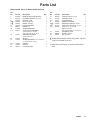
Parts Drawing
n41
n40
12
5
42
16
20
18
21
22n
232632
37
1
31
33
1
Included with 1
Model 238350, Series A
Model 824004, Series A
Model 239045, Series A
1
Purchase separately
2
2
6
43
15
05962
17
45
45
2
Included with 239045

308645 13
Parts List
Model 238350, Series A; Model 824004, Series A
Ref.
No. Part No. Description Qty.
Ref.
No. Part No. Description Qty.
1 218070 NEEDLE–DIFFUSER/SEAT KIT 1
5 238199 4-FINGER TRIGGER
(standard) 1
6 195788 HANDLE, round 1
10Y 222385 KIT, warning card 1
11Y 187348 COVER, warning 1
12 195495 TRIGGER GUARD 1
15 238817 SWIVEL, kit 1
16 179750 SPRING RETAINER 1
17n 218131 FLUID FILTER ASSEMBLY 1
(standard 50 mesh) includes
replaceable items 16, 18, 20, 21 1
18 179731 STRAINER ELEMENT 1
(standard 50 mesh)
20 179763 SPRING 1
21 179722 SPRING RETAINER (color coded blue)
(for standard 50 mesh filter) 1
22n 179733 GASKET 1
23 191244 END CAP 1
26 190973 FLUID HOUSING 1
31 105334 LOCKNUT;
M4 x 0.7 thread 1
32 177538 TRIGGER STUD 1
33 179737 ACTUATOR PIN 2
37 195419 NEEDLE HOUSING 1
39Y 222385 WARNING CARD (not shown) 1
40n 221515 SWITCHTIP SPRAY TIP,
SZ 515 1
41n 237859 RAC 1
DripLess Guard
See manual 308644 for other tip sizes 1
42 113409 RETAINER, guard 1
43 104938 O-RING, cushion 1
45 220251 KIT, tip guard 1
Y Replacement Danger and Warning labels, tags and
cards are available at no cost.
n Keep these spare parts on hand to reduce down
time.

14 308645
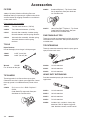
Accessories
FILTERS
3000 psi (210 bar) Maximum Working Pressure.
Adequate filtering is important for a good surface finish
and to minimize tip clogging. Elements are available in
various mesh sizes.
Filter elements and assemblies
224455 Two, 50 mesh elements, (179731)
224456 Two, 100 mesh elements, (179732)
218131 50 mesh filter assembly; includes spring,
50 mesh element and two spring retainers
218133 100 mesh filter assembly; includes spring,
100 mesh element and two spring
retainers
TOOLS
Nylon Brushes
Use to thoroughly clean the gun’s fluid passages.
101891 0.375” (9 mm) dia.
101892 0.625” (16 mm) dia.
Wrench 171147
Fits all hexes on the gun.
TIP GUARDS
These tip guards fit all Graco airless spray guns.
Choose the one that’s right for your application. One of
these tip guards is included with every Graco airless
gun.
237859 RAC
R
DripLesst
Guard.
Order SwitchTip separately. See your
distributor for available sizes.
220222 Standard DripLesst Tip Guard. Order
flat tip separately. See your distributor
for available sizes.
222674 Heavy Duty RAC
R
DripLesst Tip Guard.
Order SwitchTip separately. See your
distributor for available sizes.
FINE FINISH RAC TIPS
These tips provide and extremely fine finish with more
consistent material thickness. See your distributor for
available sizes.
TIP EXTENSIONS
These tip extensions extend tip from the spray gun to
spray hard to reach areas.
223390 12 inch extension
223391 18 inch extension
223392 24 inch extension
HEAVY DUTY EXTENSIONS
Provides extended spraying for hard to reach
applications.
224413 12 inch extension
224414 18 inch extension
224415 36 inch extension
224416 72 inch extension
236406 Includes 18 in. and 36 in. heavy duty
extension; RAC IV dripless tip guard;
180_ directional nozzle; and 45_swivel.

308645 15
Technical Data
Maximum Working Pressure 3600 psi (252 bar). . . . . .
Fluid Orifice Size 0.125 in. (3.18 mm). . . . . . . . . . . . . . .
Wetted Parts Stainless steel, Polyethylene,. . . . . . . . .
Aluminum, Polyurethane, Nylon, R
Brass, Tungsten carbide, UHMW
Weight 17 oz. (482 g). . . . . . . . . . . . . . . . . . . . . . . . . . . . .
Inlet 1/4 npsm(m)swivel. . . . . . . . . . . . . . . . . . . . . . . . . .
Maximum Material Temperature 120_F(50_C). . . . . . .
Sound Data
Sound Pressure Level 78 dB(A)*. . . . . . . . . . . . . . . .
Sound Power Level 87 dB(A)*. . . . . . . . . . . . . . . . . . .
* Measured while spraying waterbase paint – gravity
1.36 through a 517 tip at 3,000 psi (207 bar).
Per ISO 3744
R is a registered trademark
Graco Phone
Number
TO PLACE AN ORDER, contact your Graco distrib-
utor, or call this number to identify the distributor
closest to you: 1–800–690–2894 Toll Free.
PTFE
PTFE

16 308645
Graco Warranty
Graco warrants all equipment listed in this manual which is manufactured by Graco and bearing its name to be free from defects in
material and workmanship on the date of sale by an authorized Graco distributor to the original purchaser for use. With the exception of
any special extended or limited warranty published by Graco, Graco will, for a period of twelve months from the date of sale, repair or
replace any part of the equipment determined by Graco to be defective. This warranty applies only when the equipment is installed,
operated and maintained in accordance with Graco’s written recommendations.
This warranty does not cover, and Graco shall not be liable for general wear and tear, or any malfunction, damage or wear caused by
faulty installation, misapplication, abrasion, corrosion, inadequate or improper maintenance, negligence, accident, tampering, or
substitution of non-Graco component parts. Nor shall Graco be liable for malfunction, damage or wear caused by the incompatibility of
Graco equipment with structures, accessories, equipment or materials not supplied by Graco, or the improper design, manufacture,
installation, operation or maintenance or structures, accessories, equipment or materials not supplied by Graco.
This warranty is conditioned upon the prepaid return of the equipment claimed to be defective to an authorized Graco distributor for
verification of the claimed defect. If the claimed defect is verified, Graco will repair or replace free of charge any defective parts. The
equipment will be returned to the original purchaser transportation prepaid. If inspection of the equipment does not disclose any defect
in material or workmanship, repairs will be made at a reasonable charge, which charges may include the costs of parts, labor, and
transportation.
Graco’s sole obligation and buyer’s sole remedy for any breach of warranty shall be as set forth above. The buyer agrees that no other
remedy (including, but not limited to, incidental or consequential damages for lost profits, lost sales, injury to person or property, or any
other incidental or consequential loss) shall be available. Any action for breach of warranty must be brought within two (2) years of the
date of sale.
GRACO MAKES NO WARRANTY, AND DISCLAIMS ALL IMPLIED WARRANTIES OF MERCHANTABILITY AND FITNESS FOR
A PARTICULAR PURPOSE IN CONNECTION WITH ACCESSORIES, EQUIPMENT, MATERIALS OR COMPONENTS SOLD BUT
NOT MANUFACTURED BY GRACO. These items sold, but not manufactured by Graco (such as electric motors, gas engines,
switches, hose, etc.), are subject to the warranty, if any, of their manufacturer. Graco will provide purchaser with reasonable assistance
in making any claim for breach of these warranties.
In no event will Graco be liable for indirect, incidental, special or consequential damages resulting from Graco supplying equipment
hereunder, or the furnishing, performance, or use of any products or other goods sold hereto, whether due to a breach of contract,
breach of warranty, the negligence of Graco, or otherwise.
FOR GRACO CANADA CUSTOMERS
The parties acknowledge that they have required that the present document, as well as all documents, notices and legal proceedings
entered into, given or instituted pursuant hereto or relating directly or indirectly hereto, be drawn up in English. Les parties
reconnaissent avoir convenu que la rédaction du présente document sera en Anglais, ainsi que tous documents, avis et procédures
judiciaires exécutés, donnés ou intentés à la suite de ou en rapport, directement ou indirectement, avec les procédures concernées.
ADDITIONAL WARRANTY COVERAGE
Graco does provide extended warranty and wear warranty for products described in the “Graco Contractor Equipment Warranty
Program”.
All written and visual data contained in this document reflects the latest product information available at the time of publication.
Graco reserves the right to make changes at any time without notice.
Sales Offices: Minneapolis, Detroit
Foreign Offices: Belgium, Korea, Hong Kong, Japan
GRACO INC. P.O. BOX 1441 MINNEAPOLIS, MN 55440–1441
PRINTED IN U.S.A. 308645 February 1996, Revised October 1999
-
 1
1
-
 2
2
-
 3
3
-
 4
4
-
 5
5
-
 6
6
-
 7
7
-
 8
8
-
 9
9
-
 10
10
-
 11
11
-
 12
12
-
 13
13
-
 14
14
-
 15
15
-
 16
16


Ask a question and I''ll find the answer in the document
Finding information in a document is now easier with AI
Related papers
-
Graco 313749A User manual
-
-
-
Graco 3A2799A User manual
-
-
Graco Inc. 311977C User manual
-
-
-
Hitachi 288477 User manual
-
Other documents
-
-
-
-
-
-
 Allpro 289316 Operating instructions
-
-
-
-
