JL Audio sb-t-4rnr2-10w3v3-dg User manual
- Category
- Loudspeakers
- Type
- User manual

➔
➔
➔
➔
Stealthbox
®
INSTALLATION GUIDE
SB-T-4RNR2/10Wv2, JL AUDIO, Inc 2003
Sheet SKU#011181 Revision 01/13/2004
Page 1
for the
SB-T-4RNR2/10W3v2
(‘02-Up Toyota 4-Runner SR-5, Sport
Edition & Limited)
This Stealthbox is a product which
requires professional installation skills and
tools.
Please read this installation guide thor-
oughly before beginning the project. It
will guide you step by step through the
installation. Several of the steps in this
process may require two people to
accomplish.
It is absolutely vital that the enclosure
be properly mounted to the vehicle
according to these instructions. Failure
to mount the enclosure properly pres-
ents two problems: 1) The sub-bass
performance will suffer due to the
movement of the enclosure caused by
the force exerted by the woofer(s) and
2) A loose enclosure presents a serious
safety hazard in the event of a collision
or sudden deceleration.
Please enjoy your JL Audio Stealthbox
responsibly.
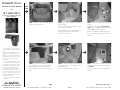
STEP 1:
Clean out all contents. Remove the
cargo cover and carpet mat.
STEP 2: Remove the rear sill plate(A) and side
storage door(B).
With the sill plate removed, pull and fold over the car-
pet out of the corner(circled).
On Limited Edition interiors, remove the plastic tray.
The flooring carpet will not fit flush aginst the
Stealthbox, once isntalled.
STEP 3:
Place the supplied wax square into
position.
The middle of wax square (X marks the
spot) needs to be 3.5” back from the wheel
well and 2.5” from the side panel.
Remove the adhesive protective paper from
the under side of the wax square and stick to
the floor.
STEP 4: Thread in the supplied tsocket cup set
screw, leaving about a 1/2” out of the Stealthbox.
Make sure that the socket cup end is exposed.
Place the Stealthbox into position and press down
firmly.
STEP 5: With the Stealthbox removed and wax
square still in position, use a 1/2” drill bit to drill out
the marked location.
After hole is drilled, remove the wax square.
STEP 6: Place and line up the hole, of one of the
supplied black metal plates to the 1/2” drilled hole
from STEP 5.
Use tape to temporary secure the metal plate into
position.
START
HERE
Continued on Next Page ➔
www.jlaudio.com
➔
➔
STEP
2.5”
3.5”
X
A
B

➔
➔
➔
STEP 7: Place the carpet that was pulled out of
the corner in STEP 2, back into position.
Cut out an access hole in the carpet, that is lined up
and position above the black metal plate’s hole, from
STEP 6.
STEP 8B: When the knob is unlocked correctly,
the exposed knob will pull away from the side panel,
but is still attached to the cleat assembly.
With the cleat unlocked, remove from the side
panel.
Cont.
From
Previous
Page
Continued on Next Page ➔
➔
STEP 8: Remove the access door(A) and cargo
net cleat(B).
Follow STEPS 8A and 8B to properly remove
the cargo net cleat.
STEP 9: Run the speaker wire to the Stealthbox’s
location.
Check for proper operation of the woofer and
attach speaker wire to terminal.
Before placing the Stealthbox back into location,
back out the threaded rod to expose about 1”.
STEP 8A: This is how the cleat looks when
installed into the side panel. (side panel not seen)
Grab a hold of the exposed knob’s edge with your
finger nails and pull out. It should not require a lot of
force. *Do not force it.*
SB-T-4RNR2/10Wv2, JL AUDIO, Inc 2003
Sheet SKU#011181 Revision 01/13/2004
Page 2
www.jlaudio.com
➔
STEP 10: With the Stealthbox wired up and in
location(with socket cup set screw placed through the car-
pet, metal plate and floor).
Place a supplied flat washer onto the supplied bolt. Place the
bolt assembly through the upper mounting support bracket
of the Stealthbox and the factory plastic side panel.
On the back side of the plastic side panel, place a supplied
flat washer, lock washer and then thread supplied nut onto
the bolt assembly .(through the removed excess door loca-
tion.)
Using a 9/16” open end wrench to hold the nut behind the
plastic panel.Tighten the exposed bolt with a 9/16” socket.
A
B
➔

Specifications:
Enclosure Type: Acoustical Suspension (Sealed)
Driver Type: 10W3v2-D2
Nominal Impedance: 4Ω
Cont. Power Handling: 300Watts
JL Audio recommends using a high quality amplifier such as the JL Audio 250/1. The diagram below shows the recommended
crossover, infrasonic filter and equalizer settings for the 250/1 when being used to power your Stealthbox®.
Supplied Hardware:
2) 3/8” Split Lock Washers
2) 3/8” Flat Washers
2) 3/8” x 1-1/4” Fender
2) 3/8”-16 x 2-1/4” hex
1) 1/4”-20 Install Bolt
1) 3/8”-16 x 2-1/4” Socket Cup Set Screw
1) 3” x 3” Wax Square
2) 3/8”-16 Hex Nut
10369 N. Commerce Pkwy, Miramar, Florida 33025-392 Phone: 954.443.1100 Fax: 954.443.1111
JL AUDIO 250/1
monoblock subwoofer amplifier
Amplifier Input Section
Input Sens.
Input Voltage
Low/High
Left Ch.
Right Ch.
Signal Sensing
Off/On
Output Mode
Full-Range/Low-Pass/High-Pass
Left Ch.
Right Ch.
Amp LP Filter
Mode/Slope
Off/12dB/24dB
Filter Freq. (Hz)
Bass Control
LF Boost (dB)
Off/30Hz
Infrasonic Filter
+1
+13
+3
+7
+10
Preamp Output Section
+12VDC Ground Remote
The JL Audio 250/1 is a very versatile audio component. Please consult the owner’s manual for detailed information
about installing and tuning this amplifier.
➔➔ ➔
STEP 11: Take the other supplied black metal
plate, lock washer, flat washer and nut to the under
side of vehicle.
STEP 12: Place the other black metal support
plate, flat washer, lock washer and thread the nut
onto the threaded rod. Use a 9/16” socket and long
extension to fully secure the mounting assembly.
If the socket cup set screw is not protruding far
enough, loosen.
STEP 13: Replace the carpet and any other con-
tents back into cargo area.
For cosmetics, we folded the corner of the carpet
back under it self. We do not recommend that you
cut this carpet.
➔
SB-T-4RNR2/10Wv2, JL AUDIO, Inc 2003
Sheet SKU#011181 Revision 01/13/2004Page 3
www.jlaudio.com
Mid/High Frequency Driver Information:
CONGRATULATIONS!
INSTALL COMPLETE.
TR690-TXI
VR650-CXI
Front Location Driver Size:
6”x9” with separated tweeter
Applicable JL Audio Products:
TR690-TXi & VR690-CXi, does require
spacer/mounting rings.
Rear Location Driver Size:
6 3/4”
Applicable JL Audio Products:
TR650-CXi,VR650-CXi & XR650-CXi,
does require spacer/mounting rings.
Cont.
From
Previous
Page
-
 1
1
-
 2
2
-
 3
3


JL Audio sb-t-4rnr2-10w3v3-dg User manual
- Category
- Loudspeakers
- Type
- User manual
Ask a question and I''ll find the answer in the document
Finding information in a document is now easier with AI
Related papers
-
JL Audio SB-GM-CFMINI/10W3v2 User manual
-
-
-
-
-
-
-
-
-