
Dell™PowerEdge™R805SystemsHardwareOwner'sManual
About Your System
Using the System Setup Program
Installing System Components
Troubleshooting Your System
Running the System Diagnostics
Jumpers and Connectors
Getting Help
Glossary
Notes, Notices, and Cautions
Information in this document is subject to change without notice.
©2007-2009DellInc.Allrightsreserved.
Reproduction in any manner whatsoever without the written permission of Dell Inc. is strictly forbidden.
Trademarks used in this text: Dell, the DELL logo, PowerEdge, and Dell OpenManage are trademarks of Dell Inc.; AMD and AMD Opteron are registered trademarks and AMD PowerNow!
is a trademark of Advanced Micro Devices; Microsoft, Windows, Windows Server, and MS-DOS are either trademarks or registered trademarks of Microsoft Corporation in the United
States and/or other countries; EMC is a registered trademark of EMC Corporation; Red Hat and Red Hat Linux are registered trademarks of Red Hat Inc.; UNIX is a registered
trademark of The Open Group in the United States and other countries.
Other trademarks and trade names may be used in this document to refer to either the entities claiming the marks and names or their products. Dell Inc. disclaims any
proprietary interest in trademarks and trade names other than its own.
June 2009 P/N TT864 Rev. A01
NOTE: A NOTE indicates important information that helps you make better use of your computer.
NOTICE: A NOTICE indicates either potential damage to hardware or loss of data and tells you how to avoid the problem.
CAUTION: A CAUTION indicates a potential for property damage, personal injury, or death.

Back to Contents Page
About Your System
Dell™PowerEdge™R805SystemsHardwareOwner'sManual
Other Information You May Need
Accessing System Features During Startup
Front-Panel Features and Indicators
Back-Panel Features and Indicators
Power Indicator Codes
NIC Indicator Codes
LCD Status Messages
System Messages
Warning Messages
Diagnostics Messages
Alert Messages
This section describes the physical, firmware, and software interface features that provide and ensure the essential functioning of your system. The physical
connectors on your system's front and back panels provide convenient connectivity and system expansion capability. The system firmware, applications, and
operating systems monitor the system and component status and alert you when a problem arises. System conditions can be reported by any of the following:
l Front or back panel indicators
l System messages
l Warning messages
l Diagnostics messages
l Alert messages
This section describes each type of message, lists the possible causes, and provides steps to resolve any problems indicated by a message. The system
indicators and features are illustrated in this section.
Other Information You May Need
l The Rack Installation Guide or Rack Installation Instructions included with your rack solution describes how to install your system into a rack.
l The Getting Started Guide provides an overview of system features, setting up your system, and technical specifications.
l CDs included with your system provide documentation and tools for configuring and managing your system.
l Systems management software documentation describes the features, requirements, installation, and basic operation of the software.
l Operating system documentation describes how to install (if necessary), configure, and use the operating system software.
l Documentation for any components you purchased separately provides information to configure and install these options.
l Updates are sometimes included with the system to describe changes to the system, software, and/or documentation.
l Release notes or readme files may be included to provide last-minute updates to the system or documentation or advanced technical reference material
intended for experienced users or technicians.
Accessing System Features During Startup
Table1-1 describes keystrokes that may be entered during startup to access system features. If your operating system begins to load before you enter the
keystroke, allow the system to finish booting, and then restart your system and try again.
Table 1-1.KeystrokesforAccessingSystemFeatures
CAUTION: The Product Information Guide provides important safety and regulatory information. Warranty information may be included within
this document or as a separate document.
NOTE: Always check for updates on support.dell.com and read the updates first because they often supersede information in other documents.
Keystroke
Description
<F2>
Enters the System Setup program. See Using the System Setup Program.
<F10>
Opens the utility partition, allowing you to run the system diagnostics. See Running the System Diagnostics
<F11>
Enters the boot mode selection screen, allowing you to choose a boot device.
<F12>
Starts PXE boot.
<Ctrl><E>
Enters the Baseboard Management Controller (BMC) Management Utility, which allows access to the system event log (SEL) and configuration of

Front-Panel Features and Indicators
Figure1-1 shows the controls, indicators, and connectors located behind the optional rack bezel on the system's front panel.
Figure 1-1. Front-Panel Features and Indicators
Table 1-2. Front-PanelLEDIndicators,Buttons,andConnectors
the remote access controller (RAC) card. See the BMC User's Guide for more information on setup and use of BMC.
<Ctrl><C>
This keystroke enters the SAS Configuration Utility. See your SAS controller User's Guide for more information.
<Ctrl><R>
If you have the optional battery-cached SAS RAID controller, this keystroke enters the RAID configuration utility. For more information, see the
documentation for your SAS controller card.
<Ctrl><S>
If you have PXE support enabled through the System Setup Program (see Integrated Devices Screen), this keystroke allows you to configure
NIC settings for PXE boot. For more information, see the documentation for your integrated NIC.
Item
Indicator, Button, or
Connector
Icon
Description
1
Power-on indicator,
power button
The power-onindicatorlightswhenthesystempowerison.
The power button controls the DC power supply output to the system. When the system bezel is installed, the power
button is not accessible.
NOTE: When powering on the system, the video monitor can take from several seconds to over 2 minutes to display
an image, depending on the amount of memory installed in the system.
NOTE: On ACPI-compliant operating systems, turning off the system using the power button causes the system to
perform a graceful shutdown before power to the system is turned off.
2
NMI button
Used to troubleshoot software and device driver errors when using certain operating systems. This button can be
pressed using the end of a paper clip.
Use this button only if directed to do so by qualified support personnel or by the operating system's documentation.
3
System identification
button
The identification buttons on the front and back panels can be used to locate a particular system within a rack. When
one of these buttons is pushed, the LCD panel on the front and the blue system status indicator on the back blink
until one of the buttons is pushed again.
4
LCD panel
Provides system ID, status information, and system error messages.
The LCD lights during normal system operation. Both the systems management software and the identification
buttons located on the front and back of the system can cause the LCD to flash blue to identify a particular system.
The LCD lights amber when the system needs attention, and the LCD panel displays an error code followed by
descriptive text.
NOTE: If the system is connected to AC power and an error has been detected, the LCD lights amber regardless of
whether the system has been powered on.
5
USB connectors (2)
Connects USB devices to the system. The ports are USB 2.0-complaint.
6
Video connector
Connects a monitor to the system.
7
Hard drives (2)
One or two 2.5-inch hot plug
8
Optical drive
(optional)
One optional slim-line SATA DVD-ROM drive or DVD-RW drive, or combination CD-RW/DVD drive (when available).
NOTE: DVD devices are data only.

Hard-Drive Indicator Codes
The hard-drive carriers have two indicators—the drive-activity indicator and the drive-status indicator. See Figure1-2. In RAID configurations, the drive-status
indicator lights to indicate the status of the drive. In non-RAID configurations, only the drive-activity indicator lights; the drive-status indicator is off.
Figure 1-2. Hard-Drive Indicators
Table1-3 lists the drive indicator patterns for RAID hard drives. Different patterns are displayed as drive events occur in the system. For example, if a hard
drive fails, the "drive failed" pattern appears. After the drive is selected for removal, the "drive being prepared for removal" pattern appears, followed by the
"drive ready for insertion or removal" pattern. After the replacement drive is installed, the "drive being prepared for operation" pattern appears, followed by
the "drive online" pattern.
Table 1-3. Hard-DriveIndicatorPatternsforRAID
Back-Panel Features and Indicators
Figure1-3 shows the controls, indicators, and connectors located on the system's back panel.
Figure 1-3. Back-Panel Features and Indicators
1
drive-status indicator (green and amber)
2
green drive-activity indicator
NOTE: For non-RAID configurations, only the drive-activity indicator is active. The drive-status indicator is off.
Condition
Drive-Status Indicator Pattern
Identify drive/preparing for removal
Blinks green two times per second
Drive ready for insertion or removal
Off
Drive predicted failure
Blinks green, amber, and off.
Drive failed
Blinks amber four times per second.
Drive rebuilding
Blinks green slowly.
Drive online
Steady green.
Rebuild aborted
Blinks green three seconds, amber three seconds, and off six seconds.
1
PCIe slot 1
2
PCIe slot 2
3
PCIe slot 3
4
PCIe slot 4
5
power supply bay 1 (PS1)
6
power supply bay 2 (PS2)

Connecting External Devices
When connecting external devices to your system, follow these guidelines:
l Most devices must be connected to a specific connector and device drivers must be installed before the device operates properly. (Device drivers are
normally included with your operating system software or with the device itself.) See the documentation that accompanied the device for specific
installation and configuration instructions.
l Always attach external devices while your system and the device are turned off. Next, turn on any external devices before turning on the system
(unless the documentation for the device specifies otherwise).
For information about individual connectors, see Jumpers and Connectors. For information about enabling, disabling, and configuring I/O ports and connectors,
see Using the System Setup Program.
Power Indicator Codes
The power button on the front panel controls the power to the system from the system's power supplies. The power indicator lights green when the system is
on.
The indicators on the redundant power supplies show whether power is present or whether a power fault has occurred (see Figure1-4). Table1-4 lists the
power supply indicator codes.
Table 1-4.RedundantPowerSupplyIndicators
Figure 1-4. Redundant Power Supply Indicators
NIC Indicator Codes
Each NIC on the back panel has an indicator that provides information on network activity and link status. See Figure1-5. Table1-5 lists the NIC indicator
codes.
Figure 1-5. NIC Indicators
7
system identification button
8
system status indicator
9
system status indicator connector
10
LOM4 connector (Gb/10Gb)1
11
LOM3 connector (Gb/10Gb)a
12
LOM2 connector (Gb)
13
LOM1 connector (Gb)
14
2.0-compliant USB connectors (2)
15
video connector
16
serial connector
17
remote access controller (RAC) connector (optional)
Indicator
Function
Power supply status
Green indicates that the power supply is operational and providing DC power to the system.
Power supply fault
Amber indicates a problem with the power supply.
AC line status
Green indicates that a valid AC source is connected to the power supply and is operational.
1
power supply status
(DC out is operational)
2
power supply fault
3
AC line status (AC in is operational)

Table 1-5. NIC Indicator Codes
LCD Status Messages
The system's control panel LCD provides status messages to signify when the system is operating correctly or when the system needs attention.
The LCD lights blue to indicate a normal operating condition, and lights amber to indicate an error condition. The LCD scrolls a message that includes a status
code followed by descriptive text. Table1-6 lists the LCD status messages that can occur and the probable cause for each message. The LCD messages refer
to events recorded in the System Event Log (SEL). For information on the SEL and configuring system management settings, see the systems management
software documentation.
Table 1-6.LCDStatusMessages
1
link indicator
2
activity indicator
Indicator
Indicator Code
Link and activity indicators are off
The NIC is not connected to the network.
Link indicator is green
The NIC is connected to a valid link partner on the network.
Activity indicator is amber blinking
Network data is being sent or received.
CAUTION: Many repairs may only be done by a certified service technician. You should only perform troubleshooting and simple repairs as
authorized in your product documentation, or as directed by the online or telephone service and support team. Damage due to servicing that is not
authorized by Dell is not covered by your warranty. Read and follow the safety instructions that came with the product.
NOTE: If your system fails to boot, press the System ID button for at least five seconds until an error code appears on the LCD. Record the code, then
see Getting Help.
Code
Text
Causes
Corrective Actions
N/A
SYSTEM NAME
A 62-character string that can be defined by the user
in the System Setup program.
The SYSTEM NAME displays under the following
conditions:
l The system is powered on.
l The power is off and active errors are
displayed.
This message is for information only.
You can change the system ID and name in the System Setup program. See
Using the System Setup Program.
E1000
FAILSAFE, Call
Support
Check the system event log for critical failure
events.
See Getting Help.
E1114
Temp Ambient
Ambient system temperature is out of acceptable
range.
See Troubleshooting System Cooling Problems.
E1118
CPU Temp
Interface
TheBMCisunabletodeterminetheCPU(s)
temperature status. Consequently, the BMC
increasestheCPUfanspeedtomaximum
asaprecautionarymeasure.
Turn off power to the system and restart the system. If the problem
persists, see Getting Help.
E1210
CMOS Batt
CMOS battery is missing, or the voltage is out of
acceptable range.
See Troubleshooting the System Battery.
E1211
ROMB Batt
RAID battery is either missing, bad, or unable to
recharge due to thermal issues.
Reseat the RAID battery connector. See RAID Battery, and Troubleshooting
System Cooling Problems.
E1214
E1216
E1217
## PwrGd
Specified voltage regulator has failed.
See Getting Help.
E1218
PCI Rsr 5V PwrGd
The 5V voltage regulator on the PCI riser has
failed.
See Getting Help.
E121A
8V PwrGd
8V voltage regulator has failed.
Recycle power to the system or clear the SEL. If the problem persists, see
Getting Help.
E121D
1.2V VM Dual
PwrGd
1.2V voltage regulator for the VM dual signal has
failed.
Recycle power to the system or clear the SEL. If the problem persists, see
Getting Help.
E1226
PCI Rsr 1.5V
PwrGd
The 1.5V voltage regulator on the PCI riser has
failed.
See Getting Help.

E1227
Linear PwrGd
Linear voltage regulator(s) has failed. Represents
status of multiple voltage regulators used in the
video and LOM circuitry.
See Getting Help.
E1229
CPU # VCORE
Processor # VCORE voltage regulator has failed.
See Getting Help.
E122A
CPU VTT PwrGd
Processor # VTT voltage has exceeded the
allowable voltage range
See Getting Help.
E122D
CPU # VDDIO
1.0V PwrGd
Processor # VDDIO voltage has exceeded the
allowable voltage range
See Getting Help.
E122E
CPU # VDDA
Processor # VDDA voltage has exceeded the
allowable voltage range
See Getting Help.
E122F
2.5V PwrGd
2.5V voltage regulator has failed.
See Getting Help.
E1231
1.2V HTCORE PwrGd
1.2V HTCORE voltage regulator has failed.
See Getting Help.
E1232
VDD 12V PS# PwrGd
The specified power supply has failed or has been
removed from the bay while the system was on.
If removed, reinsert the power supply into the bay and reconnect to power.
For component failures, see Getting Help.
E123B
LOM Mezz PwrGd
Voltage regulator for the LOM daughter card has
failed.
Recycle power to the system or clear the SEL. If the problem persists, see
Getting Help.
E123C
Planar LOM PwrGd
Voltage regulator for the integrated LOM has
failed.
Recycle power to the system or clear the SEL. If the problem persists, see
Getting Help.
E1310
RPM Fan ##
RPM of specified cooling fan is out of acceptable
operating range.
See Troubleshooting System Cooling Problems.
E1313
Fan Redundancy
The system is no longer fan-redundant. Another
fan failure will put the system at risk of over-
heating.
Check control panel LCD for additional scrolling messages. See
Troubleshooting System Cooling Problems.
E1414
CPU # Thermtrip
Specified microprocessor is out of acceptable
temperature range and has halted operation.
See Troubleshooting System Cooling Problems. If the problem persists,
ensure that the microprocessor heat sinks are properly installed. See
Troubleshooting the Microprocessors.
NOTE: The LCD continues to display this message until the system's power
cord is disconnected and reconnected to the AC power source, or the SEL is
cleared using either Server Assistant or the BMC Management Utility. See
the DellOpenManage™BaseboardManagementControllerUser'sGuide for
information about these utilities.
E1418
CPU # Presence
Specified processor is missing or bad, and the
system is in an unsupported configuration.
See Troubleshooting the Microprocessors.
E141C
CPU Mismatch
Processors are in a configuration unsupported by
Dell.
Ensure that your processors match and conform to the type described in
the Microprocessor Technical Specifications outlined in your system's Getting
Started Guide.
E141F
CPU Protocol
The system BIOS has reported a processor
protocol error.
See Getting Help.
E1421
CPU Init
The system BIOS has reported a processor
initialization error.
See Getting Help.
E1422
CPU Machine Chk
The system BIOS has reported a machine check
error.
See Getting Help.
E1610
PS # Missing
No power is available from the specified power
supply; specified power supply is improperly
installed or faulty.
See Troubleshooting Power Supplies.
E1614
PS # Status
No power is available from the specified power
supply; specified power supply is improperly
installed or faulty.
See Troubleshooting Power Supplies.
E1618
PS # Predictive
Power supply voltage is out of acceptable range;
specified power supply is improperly installed or
faulty.
See Troubleshooting Power Supplies.
E161C
PS # Input Lost
Power source for specified power supply is
unavailable, or out of acceptable range.
Check the AC power source for the specified power supply. If the problem
persists, see Troubleshooting Power Supplies.
E1620
PS # Input Range
Power source for specified power supply is
unavailable, or out of acceptable range.
Check the AC power source for the specified power supply. If the problem
persists, see Troubleshooting Power Supplies.
E1624
PS Redundancy
The power supply subsystem is no longer
redundant. If the last supply fails, the system will
go down.
See Troubleshooting Power Supplies.
E1625
PS AC Current
Power source is out of acceptable range.
Check the AC power source.
E1710
I/O Channel Chk
The system BIOS has reported an I/O channel
check.
See Getting Help.
E1711
PCI PERR B## D##
F##
The system BIOS has reported a PCI parity error
on a component that resides in PCI configuration
space at bus ##, device ##, function ##.
Remove and reseat the PCIe expansion cards. If the problem persists, see
Troubleshooting Expansion Cards.
PCI PERR Slot #
The system BIOS has reported a PCI parity error
on a component that resides in the specified PCIe
slot.
Reinstall the expansion-card riser. See Expansion-Card Risers.
If the problem persists, the riser card or system board is faulty. See Getting
Help.
E1712
PCI SERR B## D##
F##
The system BIOS has reported a PCI system error
on a component that resides in PCI configuration
space at bus ##, device ##, function ##.
Remove and reseat the PCIe expansion cards. If the problem persists, see
Troubleshooting Expansion Cards.
PCI SERR Slot #
The system BIOS has reported a PCI system error
Reinstall the expansion-card riser. See Expansion-Card Risers.

on a component that resides in the specified slot.
If the problem persists, the riser card or system board is faulty. See Getting
Help.
E1714
Unknown Err
The system BIOS has determined that there has
been an error in the system, but is unable to
determine its origin.
See Getting Help.
E171F
PCIE Fatal Err
B## D## F##
The system BIOS has reported a PCIe fatal error
on a component that resides in PCIe configuration
space at bus ##, device ##, function ##.
Remove and reseat the PCIe expansion cards. If the problem persists, see
Troubleshooting Expansion Cards.
PCIE Fatal Err
Slot #
The system BIOS has reported a PCIe fatal error
on a component that resides in the specified slot.
Reinstall the expansion-card riser. See Expansion-Card Risers.
If the problem persists, the riser card or system board is faulty. See Getting
Help.
E1810
HDD ## Fault
The SAS subsystem has determined that hard
drive ## has experienced a fault.
See Troubleshooting a Hard Drive.
E1811
HDD ## Rbld Abrt
The specified hard drive has experienced a rebuild
abort.
See Troubleshooting a Hard Drive. If the problem persists, see your RAID
documentation.
E1812
HDD ## Removed
The specified hard drive has been removed from
the system.
Information only.
E1914
DRAC5 Conn2 Cbl
DRAC 5 cable is missing or disconnected.
Reconnect the cable. See Installing a RAC Card.
E1915
IO55 HTSink
Missing
MCP55 Htsink
Missing
Heatsink sensor reports that the chipset IO55
heatsink is missing.
Heatsink sensor reports that the chipset MCP
heatsink heatsink is missing.
See Getting Help.
E1A12
PCI Rsr Missing
One or all of the PCIe risers is missing, preventing
the system from powering on.
Reinstall the missing riser card(s).
E1A14
SAS Cable A
SAS cable A is missing or bad.
Reseat the cable. If the problem persists, replace cable. See SAS Controller
Daughter Card.
E1A15
SAS Cable B
SAS cable B is missing or bad.
Reseat the cable. If the problem persists, replace cable. See SAS Controller
Daughter Card.
E1A1C
LOM Mezz Missing
LOM daughter card is missing.
Install or reseat the LOM daughter card. If the problem persists, replace the
card. See Getting Help.
E1B01
USB# Overcurrent
Device plugged in the specified USB port caused
an overcurrent condition.
Reseat the device cable. If the problem persists, replace or remove the
device.
E2010
No Memory
No memory is installed in the system.
Install memory. See Installing Memory Modules.
E2011
Mem Config Err
Memory detected, but is not configurable. Error
detected during memory configuration.
See Troubleshooting System Memory.
E2012
Unusable Memory
Memory is configured, but not usable. Memory
subsystem failure.
See Troubleshooting System Memory.
E2013
Shadow BIOS Fail
The system BIOS failed to copy its flash image into
memory.
See Troubleshooting System Memory.
E2014
CMOS Fail
CMOS failure. CMOS RAM not functioning properly.
See Getting Help.
E2015
DMA Controller
DMA controller failure.
See Getting Help.
E2016
Int Controller
Interrupt controller failure.
See Getting Help.
E2017
Timer Fail
Timer refresh failure.
See Getting Help.
E2018
Prog Timer
Programmable interval timer error.
See Getting Help.
E2019
Parity Error
Parity error.
See Getting Help.
E201A
SIO Err
SIO failure.
See Getting Help.
E201B
Kybd Controller
Keyboard controller failure.
See Getting Help.
E201C
SMI Init
System management interrupt (SMI) initialization
failure.
See Getting Help.
E201D
Shutdown Test
BIOS shutdown test failure.
See Getting Help.
E201E
POST Mem Test
BIOS POST memory test failure.
See Troubleshooting System Memory. If problem persists, see Getting Help.
E201F
DRAC Config
Dell remote access controller (DRAC) configuration
failure.
Check screen for specific error messages.
Ensure that DRAC cables and connectors are properly seated. If problem
persists, see your DRAC documentation.
E2020
CPU Config
CPU configuration failure.
Check screen for specific error messages.
E2021
Memory Population
Incorrect memory configuration. Memory
population order incorrect.
Check screen for specific error messages. See Troubleshooting System
Memory.
E2022
POST Fail
General failure after video.
Check screen for specific error messages.
E2110
MBE DIMM # & #
One of the DIMMs in the set implicated by "# & #"
has had a memory multi-bit error (MBE).
See Troubleshooting System Memory.
E2111
SBE Log Disable
DIMM #
The system BIOS has disabled memory single-bit
error (SBE) logging, and will not resume logging
further SBEs until the system is rebooted. "#"
represents the DIMM implicated by the BIOS.
See Troubleshooting System Memory.
E2112
Mem Spare DIMM #
The system BIOS has spared the memory because
it has determined that the memory had too many
errors. "# & #" represents the DIMM pair
implicated by the BIOS.
See Troubleshooting System Memory.

Solving Problems Described by LCD Status Messages
The code and text on the LCD can often specify a very precise fault condition that is easily corrected. For example, if the code E1418CPU_1_Presence
appears, you know that a microprocessor is not installed in socket 1.
In contrast, you might be able to determine the problem if multiple related errors occur. For example, if you receive a series of messages indicating multiple
voltage faults, you might determine that the problem is a failing power supply.
Removing LCD Status Messages
For faults associated with sensors, such as temperature, voltage, fans, and so on, the LCD message is automatically removed when that sensor returns to a
normal state. For example, if temperature for a component goes out of range, the LCD displays the fault; when the temperature returns to the acceptable
range, the message is removed from the LCD. For other faults, you must take action to remove the message from the display:
l Clear the SEL — You can perform this task remotely, but you will lose the event history for the system.
l Power cycle — Turn off the system and disconnect it from the electrical outlet; wait approximately ten seconds, reconnect the power cable, and restart
the system.
Any of these actions will remove fault messages, and return the status indicators and LCD colors to the normal state. Messages will reappear under the
following conditions:
l The sensor returns to a normal state but fails again, resulting in a new SEL entry.
l The system is reset and new error events are detected.
l A failure is recorded from another source that maps to the same display entry.
System Messages
Systemmessagesappearonthescreentonotifyyouofapossibleproblemwiththesystem.Table1-3 lists the system messages that can occur and the
probable cause and corrective action for each message.
Table 1-7.SystemMessages
I1910
Intrusion
System cover has been removed.
Information only.
I1911
>3 ERRs Chk Log
LCD overflow message.
A maximum of three error messages can display
sequentially on the LCD. The fourth message
displays as the standard overflow message.
Check the SEL for details on the events.
I1912
SEL Full
System Event Log is full of events, and is unable
to log any more events.
Clear the log by deleting event entries.
I1915
Video Off
(LCD lights with a
blue or amber
background.)
The video has been turned off by the RAC remote
user.
Information only.
I1916
Video Off in ##
(LCD lights with a
blue or amber
background.)
The video will be turned off in xx seconds by the
RAC remote user.
Information only.
W1228
ROMB Batt < 24hr
Warns predictively that the RAID battery has less
than 24 hours of charge left.
Replace RAID battery. See RAID Battery.
NOTE: For the full name of an abbreviation or acronym used in this table, see the Glossary.
NOTE: If you receive a system message that is not listed in Table 1-3, check the documentation for the application that is running when the message
appears or the operating system's documentation for an explanation of the message and recommended action.
CAUTION: Many repairs may only be done by a certified service technician. You should only perform troubleshooting and simple repairs as
authorized in your product documentation, or as directed by the online or telephone service and support team. Damage due to servicing that is not
authorized by Dell is not covered by your warranty. Read and follow the safety instructions that came with the product.
Message
Causes
Corrective Actions
Alert! Node Interleaving disabled!
Memory configuration does not support
Node Interleaving.
The memory configuration does not support
node interleaving, or the configuration has
changed (for example, a failed DIMM) so that
node interleaving cannot be supported. The
system will run but with reduced functionality.
Ensure that the memory modules are installed in a
configuration that supports node interleaving. Check other
system messages for additional information for possible
causes. For memory configuration information, see General
Memory Module Installation Guidelines. If the problem persists,
see Troubleshooting System Memory.
Attempting to update Remote
Remote Configuration request has been
Wait until the process is complete.

Configuration. Please wait...
detected and is being processed.
BIOS Update Attempt Failed!
Remote BIOS update attempt failed.
Retry the BIOS update. If problem persists, see Getting Help.
Caution! NVRAM_CLR jumper is installed
on system board.
NVRAM_CLR jumper is installed. CMOS has
been cleared.
Remove NVRAM_CLR jumper. See Figure6-1 for jumper
location.
CPUs with different cache sizes
detected!
Microprocessors with different cache sizes are
installed.
Ensure that all microprocessors have the same cache size and
that they are properly installed. See Processors.
Decreasing available memory
Faulty or improperly installed memory modules.
See Troubleshooting System Memory.
Error: Incorrect memory configuration
CPU n
The DIMM group for CPU n is incorrectly
configured and caused the system to halt.
See General Memory Module Installation Guidelines for memory
configuration information. If the problem persists, see
Troubleshooting System Memory.
!!*** Error: Remote Access Controller
initialization failure *** RAC virtual
USB devices may not be available...
Remote Access Controller initialization failure
Ensure that the Remote Access Controller is properly installed.
See Installing a RAC Card.
Gate A20 failure
Faulty keyboard controller; faulty system
board.
See Getting Help.
General failure
The operating system is unable to carry out
the command.
This message is usually followed by specific information. Note
the information, and take the appropriate action to resolve the
problem.
HyperTransport error caused a system
reset! Please check the system event
log for details!
A fatal system error occurred and caused the
system to reboot.
Check the SEL for information that was logged during the
error. See the applicable troubleshooting section in
Troubleshooting Your System for any faulty components
specified in the SEL.
Invalid NVRAM configuration, Resource
Re-allocated
System detected and corrected a resource
conflict.
No action is required.
Invalid PCIe card found in the
Internal_Storage slot!
The system halted because an invalid PCIe
expansion card is installed in the dedicated
storage controller slot.
Remove the PCIe expansion card and install either the internal
SAS controller in the dedicated slot.
Keyboard Controller failure
Faulty keyboard controller; faulty system board
See Getting Help.
Manufacturing mode detected
System is in manufacturing mode.
Reboot to take the system out of manufacturing mode.
Memory address line failure at address
,
read value expecting value
Memory double word logic failure at
address, read value expecting value
Memory odd/even logic failure at
address, read value expecting value
Memory write/read failure at address,
read value expecting value
Faulty or improperly installed memory modules.
See Troubleshooting System Memory.
Memory tests terminated by keystroke.
POST memory test terminated by pressing the
spacebar.
Information only.
No boot device available
Faulty or missing optical drive subsystem, hard
drive, or hard-drive subsystem, or no bootable
USB key installed.
Use a bootable USB key, CD, or hard drive. If the problem
persists, see Troubleshooting an SD Card or Internal USB Key
and Troubleshooting a Hard Drive. See Using the System Setup
Program for information on setting the order of boot devices.
No boot sector on hard drive
Incorrect configuration settings in System
Setup program, or no operating system on
hard drive.
Check the hard-drive configuration settings in the System
Setup program. See Using the System Setup Program. If
necessary, install the operating system on your hard drive.
See your operating system documentation.
No timer tick interrupt
Faulty system board.
See "Getting Help."
Optical drive not found
Cable is not properly seated, or drive missing.
See Troubleshooting an Optical Drive.
PCI BIOS failed to install
PCIe device BIOS (Option ROM) checksum
failure detected during shadowing.
Cables to expansion card(s) loose; faulty or
improperly installed expansion card(s).
Reseat the expansion card(s). Ensure that all appropriate
cables are securely connected to the expansion card(s). If the
problem persists, see Troubleshooting Expansion Cards.
PCIe Degraded Link Width Error:
Embedded device
Expected Link Width is n
Actual Link Width is n
Faulty system board or riser board.
See Getting Help.
PCIe Degraded Link Width Error:
Integrated device
Expected Link Width is n
Actual Link Width is n
The specified PCIe device is faulty or
improperly installed.
For a SAS controller daughter card, reseat the card in the
dedicated PCIe connector. See Installing a SAS Controller
Daughter Card. If the problem persists, see Getting Help.
PCIe Degraded Link Width Error: Slot n
Expected Link Width is n
Actual Link Width is n
Faulty or improperly installed PCIe card in the
specified slot.
Reseat the PCIe card in the specified slot number. See
Expansion Cards. If the problem persists, see Getting Help.
PCIe Training Error: Embedded device
Faulty system board or riser board.
See Getting Help.

Warning Messages
A warning message alerts you to a possible problem and prompts you to respond before the system continues a task. For example, before you format a hard
PCIe Training Error: Integrated device
The specified PCIe device is faulty or
improperly installed.
For a SAS controller daughter card, reseat the card in the
dedicated PCIe connector. See Installing a SAS Controller
Daughter Card. If the problem persists, see Getting Help.
PCIeTrainingError:Slotn
Faulty or improperly installed PCIe card in the
specified slot.
Reseat the PCIe card in the specified slot number. See
Expansion Cards. If the problem persists, see Getting Help.
Plug & Play Configuration Error
Error encountered in initializing PCIe device;
faulty system board.
Install the NVRAM_CLR jumper and reboot the system. See
Figure6-1 for jumper location. If the problem persists, see
Troubleshooting Expansion Cards.
Read fault
Requested sector not found
The operating system cannot read from the
hard drive or USB device, the system could not
find a particular sector on the disk, or the
requested sector is defective.
Replace the USB medium or device. Ensure that the USB or
hard drive cables are properly connected. See Troubleshooting
a USB Device, or Troubleshooting a Hard Drive for the
appropriate drive(s) installed in your system.
Remote Access Controller cable error or
incorrect card in the RAC slot.
RAC cables not connected, or RAC card
installed in wrong expansion slot.
Check that the RAC cables are connected, and that the RAC
card is installed in the correct expansion slot. See Installing a
RAC Card.
Remote configuration update attempt
failed
System unable to process Remote
Configuration request
Retry Remote Configuration.
ROM bad checksum = address
Expansion card improperly installed or faulty.
Reseat the expansion card(s). Ensure that all appropriate
cables are securely connected to the expansion card(s). If the
problem persists, see Troubleshooting Expansion Cards.
Sector not found
Seek error
Seek operation failed
Faulty hard drive, USB device, or. USB medium.
See Troubleshooting a USB Device or Troubleshooting a Hard
Drive for the appropriate drive(s) installed in your system.
Shutdown failure
Shutdown test failure.
See Troubleshooting System Memory.
The amount of system memory has changed
Memory has been added or removed or a
memory module may be faulty.
If memory has been added or removed, this message is
informative and can be ignored. If memory has not been added
or removed, check the SEL to determine if single-bit or multi-bit
errors were detected and replace the faulty memory module.
See Troubleshooting System Memory.
This system supports only Opteron(TM)
2000 series processors.
Microprocessor(s) is not supported by the
system.
Install a supported microprocessor or microprocessor
combination. See Installing a Processor.
Time-of-day clock stopped
Faulty battery or faulty chip.
See Troubleshooting the System Battery.
Time-of-day not set - please run SETUP
program
Incorrect Time or Date settings; faulty system
battery.
Check the Time and Date settings. See Using the System
Setup Program. If the problem persists, replace the system
battery. See System Battery.
Timer chip counter 2 failed
Faulty system board.
See Getting Help.
Unsupported CPU combination
Unsupported CPU stepping detected
Microprocessor(s) is not supported by the
system.
Install a supported microprocessor or microprocessor
combination. See Processors.
TPM failure
A Trusted Platform Module (TPM) function has
failed.
See Getting Help.
Utility partition not available
The <F10> key was pressed during POST, but
no utility partition exists on the boot hard
drive.
Create a utility partition on the boot hard drive. See the CDs
that came with your system.
Warning: Following faulty DIMMs are
disabled:
DIMM n1 n2
Total memory size is reduced.
Faulty or improperly seated memory module(s).
DIMMs are disabled in pairs, as indicated by
the n1 and n2. Check both DIMMs for a
possible fault.
See Troubleshooting System Memory.
Warning: A fatal error has caused
system reset! Please check the system
event log!
A fatal system error occurred and caused the
system to reboot.
Check the SEL for information that was logged during the
error. See the applicable troubleshooting section in
Troubleshooting Your System for any faulty components
specified in the SEL.
Warning! No micro code update loaded
for processor n
Micro code update failed.
Update the BIOS firmware. See Getting Help.
Warning: One or more faulty DIMMs found
on CPUn
Faulty or improperly seated memory module(s)
used by CPUn.
See Troubleshooting System Memory.
Warning: The installed memory
configuration is not optimal. For more
information on valid memory
configurations, please see the system
documentation on the technical support
web site.
Invalid memory configuration. The system will
run but with reduced functionality.
Ensure that the memory modules are installed in a valid
configuration. See General Memory Module Installation
Guidelines. If the problem persists, see Troubleshooting
System Memory.
Write fault
Write fault on selected drive
Faulty USB device, USB medium, optical drive
assembly, hard drive, or hard-drive subsystem.
See Troubleshooting a USB Device, Troubleshooting an SD
Card or Internal USB Key, and Troubleshooting a Hard Drive.
NOTE: For the full name of an abbreviation or acronym used in this table, see the Glossary.

drive, a message will warn you that you may lose all data on the hard drive. Warning messages usually interrupt the task and require you to respond by
typing y (yes) or n (no).
Diagnostics Messages
When you run system diagnostics, an error message may result. Diagnostic error messages are not covered in this section. Record the message on a copy of
the Diagnostics Checklist in Getting Help, and then follow the instructions in that section for obtaining technical assistance.
Alert Messages
Systems management software generates alert messages for your system. Alert messages include information, status, warning, and failure messages for
drive, temperature, fan, and power conditions. For more information, see the systems management software documentation.
Back to Contents Page
NOTE: Warning messages are generated by either the application or the operating system. For more information, see the documentation that
accompanied the operating system or application.

Back to Contents Page
Dell™PowerEdge™R805SystemsHardwareOwner'sManual
Notes, Notices, and Cautions
Information in this document is subject to change without notice.
©2007-2009DellInc.Allrightsreserved.
Reproduction in any manner whatsoever without the written permission of Dell Inc. is strictly forbidden.
Trademarks used in this text: Dell, the DELL logo, PowerEdge, and Dell OpenManage are trademarks of Dell Inc.; AMD and AMD Opteron are registered trademarks and AMD PowerNow!
is a trademark of Advanced Micro Devices; Microsoft, Windows, Windows Server, and MS-DOS are either trademarks or registered trademarks of Microsoft Corporation in the United
States and/or other countries; EMC is a registered trademark of EMC Corporation; Red Hat and Red Hat Linux are registered trademarks of Red Hat Inc.; UNIX is a registered
trademark of The Open Group in the United States and other countries.
Other trademarks and trade names may be used in this document to refer to either the entities claiming the marks and names or their products. Dell Inc. disclaims any
proprietary interest in trademarks and trade names other than its own.
June 2009 P/N TT864 Rev. A01
Back to Contents Page
NOTE: A NOTE indicates important information that helps you make better use of your computer.
NOTICE: A NOTICE indicates either potential damage to hardware or loss of data and tells you how to avoid the problem.
CAUTION: A CAUTION indicates a potential for property damage, personal injury, or death.

Back to Contents Page
Running the System Diagnostics
Dell™PowerEdge™R805SystemsHardwareOwner'sManual
Using Server Administrator Diagnostics
System Diagnostics Features
When to Use the System Diagnostics
Running the System Diagnostics
System Diagnostics Testing Options
Using the Custom Test Options
If you experience a problem with your system, run the diagnostics before calling for technical assistance. The purpose of the diagnostics is to test your
system's hardware without requiring additional equipment or risking data loss. If you are unable to fix the problem yourself, service and support personnel can
use diagnostics test results to help you solve the problem.
Using Server Administrator Diagnostics
To assess a system problem, first use the online Server Administrator diagnostics. If you are unable to identify the problem, then use the system diagnostics.
To access the online diagnostics, log into the Server Administrator home page, and then click the Diagnostics tab. For information about using diagnostics, see
the online help. For additional information, see the Server Administrator User's Guide.
System Diagnostics Features
The system diagnostics provides a series of menus and options for particular device groups or devices. The system diagnostics menus and options allow you
to:
l Run tests individually or collectively.
l Control the sequence of tests.
l Repeat tests.
l Display, print, or save test results.
l Temporarily suspend testing if an error is detected or terminate testing when a user-defined error limit is reached.
l View help messages that briefly describe each test and its parameters.
l View status messages that inform you if tests are completed successfully.
l View error messages that inform you of problems encountered during testing.
When to Use the System Diagnostics
If a major component or device in the system does not operate properly, component failure may be indicated. As long as the microprocessor and the system's
input/output devices (monitor, keyboard, and diskette drive) are functioning, you can use the system diagnostics to help identify the problem.
Running the System Diagnostics
The system diagnostics is run from the utility partition on your hard drive.
1. As the system boots, press <F10> during POST.
2. From the utility partition main menu, select Run System Diagnostics, or select Run Memory Diagnostics if you are troubleshooting memory.
When you start the system diagnostics, a message is displayed stating that the diagnostics are initializing. Next, the Diagnostics menu appears. The menu
allows you to run all or specific diagnostics tests or to exit the system diagnostics.
System Diagnostics Testing Options
NOTICE: Use the system diagnostics to test only your system. Using this program with other systems may cause invalid results or error messages. In
addition, use only the program that came with your system (or an updated version of that program).
NOTE: Before you read the rest of this section, start the system diagnostics so that you can see the utility on your screen.

Click the testing option in the Main Menu window. Table5-1 provides a brief explanation of testing options.
Table 5-1.SystemDiagnosticsTestingOptions
Using the Custom Test Options
When you select Custom Test in the Main Menu window, the Customize window appears and allows you to select the device(s) to be tested, select specific
options for testing, and view the test results.
Selecting Devices for Testing
The left side of the Customize window lists devices that can be tested. Devices are grouped by device type or by module, depending on the option you select.
Click the (+) next to a device or module to view its components. Click (+) on any component to view the tests that are available. Clicking a device, rather
than its components, selects all of the components of the device for testing.
Selecting Diagnostics Options
Use the Diagnostics Options area to select how you want to test a device. You can set the following options:
l Non-Interactive Tests Only — When checked, runs only tests that require no user intervention.
l Quick Tests Only — When checked, runs only the quick tests on the device. Extended tests will not run when you select this option.
l Show Ending Timestamp — When checked, time stamps the test log.
l Test Iterations — Selects the number of times the test is run.
l Log output file pathname — When checked, enables you to specify where the test log file is saved.
Viewing Information and Results
The tabs in the Customize window provide information about the test and the test results. The following tabs are available:
l Results — Displays the test that ran and the result.
l Errors — Displays any errors that occurred during the test.
l Help — Displays information about the currently selected device, component, or test.
l Configuration — Displays basic configuration information about the currently selected device.
l Parameters — If applicable, displays parameters that you can set for the test.
Back to Contents Page
Testing
Option
Function
Express Test
Performs a quick check of the system. This option runs device tests that do not require user interaction. Use this option to quickly identify the
source of your problem.
Extended Test
Performs a more thorough check of the system. This test can take an hour or longer.
Custom Test
Tests a particular device.
Information
Displays test results.

Back to Contents Page
Getting Help
Dell™PowerEdge™R805SystemsHardwareOwner'sManual
Contacting Dell
Contacting Dell
For customers in the United States, call 800-WWW-DELL (800-999-3355).
Dell provides several online and telephone-based support and service options. Availability varies by country and product, and some services may not be
available in your area. To contact Dell for sales, technical support, or customer service issues:
1. Visit support.dell.com.
2. Verify your country or region in the Choose A Country/Region drop-down menu at the bottom of the page.
3. Click Contact Us on the left side of the page.
4. Select the appropriate service or support link based on your need.
Choose the method of contacting Dell that is convenient for you.
Back to Contents Page
NOTE: If you do not have an active Internet connection, you can find contact information on your purchase invoice, packing slip, bill, or Dell product
catalog.

Back to Contents Page
Glossary
Dell™PowerEdge™R805SystemsHardwareOwner'sManual
This section defines or identifies technical terms, abbreviations, and acronyms used in your system documents.
A — Ampere(s).
AC — Alternating current.
ACPI — Advanced Configuration and Power Interface. A standard interface for enabling the operating system to direct configuration and power
management.
ambient temperature — The temperature of the area or room where the system is located.
ANSI — American National Standards Institute. The primary organization for developing technology standards in the U.S.
application — Software designed to help you perform a specific task or series of tasks. Applications run from the operating system.
ASCII — American Standard Code for Information Interchange.
asset tag — An individual code assigned to a system, usually by an administrator, for security or tracking purposes.
backup — A copy of a program or data file. As a precaution, back up your system's hard drive on a regular basis. Before making a change to the
configuration of your system, back up important start-up files from your operating system.
backup battery — A battery that maintains system configuration, date, and time information in a special section of memory when the system is turned off.
beep code — A diagnostic message in the form of a pattern of beeps from your system's speaker. For example, one beep, followed by a second beep, and
then a burst of three beeps is beep code 1-1-3.
BIOS — Basic input/output system. Your system's BIOS contains programs stored on a flash memory chip. The BIOS controls the following:
l Communications between the processor and peripheral devices
l Miscellaneous functions, such as system messages
bit — The smallest unit of information interpreted by your system.
blade — A module that contains a processor, memory, and a hard drive. The modules are mounted into a chassis that includes power supplies and fans.
BMC — Baseboard management controller.
boot routine — A program that clears all memory, initializes devices, and loads the operating system when you start your system. Unless the operating
systemfailstorespond,youcanreboot(alsocalledwarm boot) your system by pressing <Ctrl><Alt><Del>. Otherwise, you must restart the system by
pressing the reset button or by turning the system off and then back on.
bootable diskette — A diskette that is used to start your system if the system will not boot from the hard drive.
BTU — British thermal unit.
bus — An information pathway between the components of a system. Your system contains an expansion bus that allows the processor to communicate
with controllers for the peripheral devices connected to the system. Your system also contains an address bus and a data bus for communications between
the processor and RAM.
C — Celsius.
cache — A fast storage area that keeps a copy of data or instructions for quick data retrieval. When a program makes a request to a disk drive for data that
is in the cache, the disk-cache utility can retrieve the data from RAM faster than from the disk drive.
CD — Compact disc. CD drives use optical technology to read data from CDs.
cm — Centimeter(s).
cmos — Complementary metal-oxide semiconductor.
component — As they relate to DMI, components include operating systems, computer systems, expansion cards, and peripherals that are compatible with
DMI. Each component is made up of groups and attributes that are defined as relevant to that component.
COMn — The device names for the serial ports on your system.
control panel — The part of the system that contains indicators and controls, such as the power button and power indicator.
controller — A chip that controls the transfer of data between the processor and memory or between the processor and a peripheral.
conventional memory — The first 640 KB of RAM. Conventional memory is found in all systems. Unless they are specially designed, MS-DOS®programs are
limited to running in conventional memory.
coprocessor — A chip that relieves the system's processor of specific processing tasks. A math coprocessor, for example, handles numeric processing.
CPU — Central processing unit. See processor.
DC — Direct current.
DDR — Double-data rate. A technology in memory modules that potentially doubles the output.
device driver — A program that allows the operating system or some other program to interface correctly with a peripheral. Some device drivers—such as
network drivers—must be loaded from the config.sys file or as memory-resident programs (usually, from the autoexec.bat file). Others must load when you
start the program for which they were designed.
DHCP — Dynamic Host Configuration Protocol. A method of automatically assigning an IP address to a client system.
diagnostics — A comprehensive set of tests for your system.
DIMM — Dual in-line memory module. See also memory module.
DIN — Deutsche Industrie Norm.
directory — Directories help keep related files organized on a disk in a hierarchical, "inverted tree" structure. Each disk has a "root" directory. Additional
directories that branch off the root directory are called subdirectories. Subdirectories may contain additional directories branching off them.
DMA — Direct memory access. A DMA channel allows certain types of data transfer between RAM and a device to bypass the processor.
DMI — Desktop Management Interface. DMI enables the management of your system's software and hardware by collecting information about the system's
components, such as the operating system, memory, peripherals, expansion cards, and asset tag.

DNS — Domain Name System. A method of translating Internet domain names, such as www.dell.com, into IP addresses, such as 143.166.83.200.
DRAM — Dynamic random-access memory. A system's RAM is usually made up entirely of DRAM chips.
DVD — Digital versatile disc.
ECC — Error checking and correction.
EEPROM — Electronically erasable programmable read-only memory.
EMC — Electromagnetic compatibility.
EMI — Electromagnetic interference.
ERA — Embedded remote access. ERA allows you to perform remote, or "out-of-band," server management on your network server using a remote access
controller.
ESD — Electrostatic discharge.
ESM — Embedded server management.
expansion bus — Your system contains an expansion bus that allows the processor to communicate with controllers for peripherals, such as NICs.
expansion card — An add-in card, such as a NIC or SCSI adapter, that plugs into an expansion-card connector on the system board. An expansion card adds
some specialized function to the system by providing an interface between the expansion bus and a peripheral.
expansion-card connector — A connector on the system board or riser board for plugging in an expansion card.
F — Fahrenheit.
FAT — File allocation table. The file system structure used by MS-DOS to organize and keep track of file storage. The Microsoft®Windows®operating
systems can optionally use a FAT file system structure.
flash memory — A type of EEPROM chip that can be reprogrammed from a utility on diskette while still installed in a system; most EEPROM chips can only be
rewritten with special programming equipment.
format — To prepare a hard drive or diskette for storing files. An unconditional format deletes all data stored on the disk.
FSB — Front-side bus. The FSB is the data path and physical interface between the processor and the main memory (RAM).
ft — Feet.
FTP — File transfer protocol.
g — Gram(s).
G — Gravities.
Gb — Gigabit(s);1024megabitsor1,073,741,824bits.
GB — Gigabyte(s);1024megabytesor1,073,741,824bytes.However,whenreferringtohard-drive capacity, the term is usually rounded to 1,000,000,000
bytes.
graphics mode — A video mode that can be defined as x horizontal by y vertical pixels by z colors.
group — As it relates to DMI, a group is a data structure that defines common information, or attributes, about a manageable component.
guarding — A type of data redundancy in which a set of physical drives stores data and an additional drive stores parity data. See also mirroring, striping,
and RAID.
h — Hexadecimal. A base-16 numbering system, often used in programming to identify addresses in the system's RAM and I/O memory addresses for
devices. In text, hexadecimal numbers are often followed by h.
headless system — A system or device that functions without having a keyboard, mouse, or monitor attached. Normally, headless systems are managed
over a network using an Internet browser.
host adapter — A host adapter implements communication between the system's bus and the controller for a peripheral device. (Hard-drive controller
subsystems include integrated host adapter circuitry.) To add a SCSI expansion bus to your system, you must install or connect the appropriate host
adapter.
Hz — Hertz.
I/O — Input/output. A keyboard is an input device, and a monitor is an output device. In general, I/O activity can be differentiated from computational
activity.
ID — Identification.
IDE — Integrated drive electronics. A standard interface between the system board and storage devices.
integrated mirroring — Provides simultaneous physical mirroring of two drives. Integrated mirroring functionality is provided by the system's hardware. See
also mirroring.
internal processor cache — An instruction and data cache built into the processor.
IP — Internet Protocol.
IPX — Internet package exchange.
IRQ — Interrupt request. A signal that data is about to be sent to or received by a peripheral device travels by an IRQ line to the processor. Each peripheral
connection must be assigned an IRQ number. Two devices can share the same IRQ assignment, but you cannot operate both devices simultaneously.
jumper — Small blocks on a circuit board with two or more pins emerging from them. Plastic plugs containing a wire fit down over the pins. The wire connects
the pins and creates a circuit, providing a simple and reversible method of changing the circuitry in a board.
K — Kilo-; 1000.
Kb — Kilobit(s); 1024 bits.
KB — Kilobyte(s); 1024 bytes.
Kbps — Kilobit(s) per second.
KBps — Kilobyte(s) per second.
key combination — A command requiring you to press multiple keys at the same time (for example, <Ctrl><Alt><Del>).
kg — Kilogram(s); 1000 grams.
kHz — Kilohertz.
KMM — Keyboard/monitor/mouse.
KVM — Keyboard/video/mouse. KVM refers to a switch that allows selection of the system from which the video
is displayed and for which the keyboard and mouse are used.

LAN — Local area network. A LAN is usually confined to the same building or a few nearby buildings, with all equipment linked by wiring dedicated specifically
to the LAN.
lb — Pound(s).
LCD — Liquid crystal display.
LED — Light-emittingdiode.Anelectronicdevicethatlightsupwhenacurrentispassedthroughit.
LGA—Land grid array. A type of processor socket. Unlike the PGA, the LGA interface has no pins on the chip; instead, the chip has pads that contact pins on
the system board.
Linux — An operating system similar to the UNIX® operating system that runs on a variety of hardware systems. Linux is open source software, which is
freely available; however, the full distribution of Linux along with technical support and training are available for a fee from vendors such as Red Hat®
Linux®software.
local bus — On a system with local-bus expansion capability, certain peripheral devices (such as the video adapter circuitry) can be designed to run much
faster than they would with a traditional expansion bus. See also bus.
LVD — Low voltage differential.
m — Meter(s).
mA — Milliampere(s).
MAC address — Media Access Control address. Your system's unique hardware number on a network.
mAh — Milliampere-hour(s).
Mb — Megabit(s); 1,048,576 bits.
MB — Megabyte(s); 1,048,576 bytes. However, when referring to hard-drive capacity, the term is often rounded to mean 1,000,000 bytes.
Mbps — Megabits per second.
MBps — Megabytes per second.
MBR — Master boot record.
memory address — A specific location, usually expressed as a hexadecimal number, in the system's RAM.
memory module — A small circuit board containing DRAM chips that connects to the system board.
memory — An area in your system that stores basic system data. A system can contain several different forms of memory, such as integrated memory (ROM
and RAM) and add-in memory modules (DIMMs).
MHz — Megahertz.
mirroring — A type of data redundancy in which a set of physical drives stores data and one or more sets of additional drives stores duplicate copies of the
data. Mirroring functionality is provided by software. See also guarding, integrated mirroring, striping, and RAID.
mm — Millimeter(s).
ms — Millisecond(s).
NAS — Network Attached Storage. NAS is one of the concepts used for implementing shared storage on a network. NAS systems have their own operating
systems, integrated hardware, and software that are optimized to serve specific storage needs.
NIC — Network interface controller. A device that is installed or integrated in a system to allow connection to a network.
NMI — Nonmaskable interrupt. A device sends an NMI to signal the processor about hardware errors.
ns — Nanosecond(s).
NTFS — TheNTFileSystemoptionintheWindows2000operatingsystem.
NVRAM — Nonvolatile random-access memory. Memory that does not lose its contents when you turn off your system. NVRAM is used for maintaining the
date, time, and system configuration information.
parity — Redundant information that is associated with a block of data.
partition — You can divide a hard drive into multiple physical sections called partitions with the fdisk command. Each partition can contain multiple logical
drives. You must format each logical drive with the format command.
PCI — Peripheral Component Interconnect. A standard for local-bus implementation.
PDU — Power distribution unit. A power source with multiple power outlets that provides electrical power to servers and storage systems in a rack.
peripheral — An internal or external device, such as a diskette drive or keyboard, connected to a system.
PGA — Pin grid array. A type of processor socket that allows you to remove the processor chip.
pixel — A single point on a video display. Pixels are arranged in rows and columns to create an image. A video resolution, such as 640 x 480, is expressed
as the number of pixels across by the number of pixels up and down.
POST — Power-on self-test. Before the operating system loads when you turn on your system, the POST tests various system components such as RAM and
hard drives.
processor — The primary computational chip inside the system that controls the interpretation and execution of arithmetic and logic functions. Software
written for one processor must usually be revised to run on another processor. CPU is a synonym for processor.
protected mode — An operating mode that allows operating systems to implement:
l A memory address space of 16 MB to 4 GB
l Multitasking
l Virtual memory, a method for increasing addressable memory by using the hard drive
The Windows 2000 and UNIX 32-bit operating systems run in protected mode. MS-DOS cannot run in protected mode.
PS/2 — Personal System/2.
PXE — Preboot eXecution Environment. A way of booting a system via a LAN (without a hard drive or bootable diskette).
RAC — Remote access controller.
RAID — Redundantarrayofindependentdisks.Amethodofprovidingdataredundancy.SomecommonimplementationsofRAIDincludeRAID0,RAID1,
RAID5,RAID10,andRAID50.Seealsoguarding, mirroring, and striping.
RAM — Random-access memory. The system's primary temporary storage area for program instructions and data. Any information stored in RAM is lost when
you turn off your system.
RAS — Remote Access Service. This service allows users running the Windows operating system to remotely access a network from their system using a
modem.

readme file — A text file, usually shipped with software or hardware, that contains information supplementing or updating the product's documentation.
read-only file — A read-only file is one that you are prohibited from editing or deleting.
ROM — Read-only memory. Your system contains some programs essential to its operation in ROM code. A ROM chip retains its contents even after you turn
off your system. Examples of code in ROM include the program that initiates your system's boot routine and the POST.
ROMB — RAID on motherboard.
rpm — Revolutions per minute.
RTC — Real-time clock.
SAS — Serial-attached SCSI.
SATA — Serial Advanced Technology Attachment. A standard interface between the system board and storage devices.
SCSI — Small computer system interface. An I/O bus interface with faster data transmission rates than standard ports.
SDRAM — Synchronous dynamic random-access memory.
sec — Second(s).
serial port — An I/O port used most often to connect a modem to your system. You can usually identify a serial port on your system by its 9-pin connector.
service tag — AbarcodelabelonthesystemusedtoidentifyitwhenyoucallDell™fortechnicalsupport.
simple disk volume — The volume of free space on a single dynamic, physical disk.
SMART — Self-Monitoring Analysis and Reporting Technology. Allows hard drives to report errors and failures to the system BIOS and then display an error
message on the screen.
SMP — Symmetric multiprocessing. Used to describe a system that has two or more processors connected via a high-bandwidth link and managed by an
operating system, where each processor has equal access to I/O devices.
SNMP — Simple Network Management Protocol. A standard interface that allows a network manager to remotely monitor and manage workstations.
spanning — Spanning, or concatenating, disk volumes combines unallocated space from multiple disks into one logical volume, allowing more efficient use of
all the space and all drive letters on a multiple-disk system.
striping — Disk striping writes data across three or more disks in an array, but only uses a portion of the space on each disk. The amount of space used by a
"stripe" is the same on each disk used. A virtual disk may use several stripes on the same set of disks in an array. See also guarding, mirroring, and RAID.
SVGA — Super video graphics array. VGA and SVGA are video standards for video adapters with greater resolution and color display capabilities than
previous standards.
system board — As the main circuit board, the system board usually contains most of your system's integral components, such as the processor, RAM,
controllers for peripherals, and various ROM chips.
system configuration information — Data stored in memory that tells a system what hardware is installed and how the system should be configured for
operation.
system diskette — See bootable diskette.
system memory — See RAM.
System Setup program — A BIOS-based program that allows you to configure your system's hardware and customize the system's operation by setting
features such as password protection. Because the System Setup program is stored in NVRAM, any settings remain in effect until you change them again.
system.ini file — A start-up file for the Windows operating system. When you start Windows, it consults the system.ini file to determine a variety of options
for the Windows operating environment. Among other things, the system.ini file records which video, mouse, and keyboard drivers are installed for
Windows.
TCP/IP — Transmission Control Protocol/Internet Protocol.
termination — Some devices (such as the last device at each end of a SCSI cable) must be terminated to prevent reflections and spurious signals in the
cable. When such devices are connected in a series, you may need to enable or disable the termination on these devices by changing jumper or switch
settings on the devices or by changing settings in the configuration software for the devices.
UNIX — UniversalInternetExchange.UNIX,theprecursortoLinux,isanoperatingsystemwrittenintheCprogramminglanguage.
uplink port — A port on a network hub or switch used to connect to other hubs or switches without requiring a crossover cable.
UPS — Uninterruptible power supply. A battery-powered unit that automatically supplies power to your system in the event of an electrical failure.
USB — Universal Serial Bus. A USB connector provides a single connection point for multiple USB-compliant devices, such as mice and keyboards. USB devices
can be connected and disconnected while the system is running.
utility — A program used to manage system resources—memory, disk drives, or printers, for example.
UTP — Unshielded twisted pair. A type of wiring used to connect systems in a business or home to a telephone line.
V — Volt(s).
VAC — Volt(s) alternating current.
VDC — Volt(s) direct current.
VGA — Video graphics array. VGA and SVGA are video standards for video adapters with greater resolution and color display capabilities than previous
standards.
video adapter — The logical circuitry that provides (in combination with the monitor) your system's video capabilities. A video adapter may be integrated into
the system board or may be an expansion card that plugs into an expansion slot.
video driver — A program that allows graphics-mode application programs and operating systems to display at a chosen resolution with the desired number
of colors. Video drivers may need to match the video adapter installed in the system.
video memory — Most VGA and SVGA video adapters include memory chips in addition to your system's RAM. The amount of video memory installed primarily
influences the number of colors that a program can display (with the appropriate video drivers and monitor capabilities).
video resolution — Video resolution (800 x 600, for example) is expressed as the number of pixels across by the number of pixels up and down. To display a
program at a specific graphics resolution, you must install the appropriate video drivers and your monitor must support the resolution.
W — Watt(s).
WH — Watt-hour(s).
win.ini file — A start-up file for the Windows operating system. When you start Windows, it consults the win.ini file to determine a variety of options for the
Windows operating environment. The win.ini file also usually includes sections that contain optional settings for Windows application programs that are
installed on the hard drive.
Windows 2000 — An integrated and complete Microsoft Windows operating system that does not require MS-DOSandthatprovidesadvancedoperating
system performance, improved ease of use, enhanced workgroup functionality, and simplified file management and browsing.
Page is loading ...
Page is loading ...
Page is loading ...
Page is loading ...
Page is loading ...
Page is loading ...
Page is loading ...
Page is loading ...
Page is loading ...
Page is loading ...
Page is loading ...
Page is loading ...
Page is loading ...
Page is loading ...
Page is loading ...
Page is loading ...
Page is loading ...
Page is loading ...
Page is loading ...
Page is loading ...
Page is loading ...
Page is loading ...
Page is loading ...
Page is loading ...
Page is loading ...
Page is loading ...
Page is loading ...
Page is loading ...
Page is loading ...
Page is loading ...
Page is loading ...
Page is loading ...
Page is loading ...
Page is loading ...
Page is loading ...
Page is loading ...
Page is loading ...
Page is loading ...
Page is loading ...
Page is loading ...
Page is loading ...
Page is loading ...
Page is loading ...
Page is loading ...
Page is loading ...
Page is loading ...
Page is loading ...
Page is loading ...
Page is loading ...
Page is loading ...
Page is loading ...
Page is loading ...
Page is loading ...
Page is loading ...
Page is loading ...
Page is loading ...
Page is loading ...
Page is loading ...
Page is loading ...
Page is loading ...
Page is loading ...
Page is loading ...
Page is loading ...
Page is loading ...
-
 1
1
-
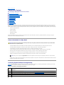 2
2
-
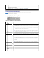 3
3
-
 4
4
-
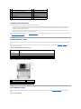 5
5
-
 6
6
-
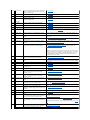 7
7
-
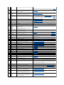 8
8
-
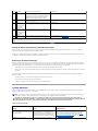 9
9
-
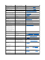 10
10
-
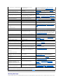 11
11
-
 12
12
-
 13
13
-
 14
14
-
 15
15
-
 16
16
-
 17
17
-
 18
18
-
 19
19
-
 20
20
-
 21
21
-
 22
22
-
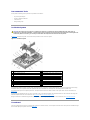 23
23
-
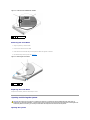 24
24
-
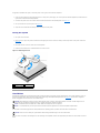 25
25
-
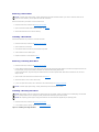 26
26
-
 27
27
-
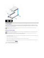 28
28
-
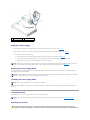 29
29
-
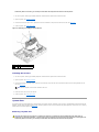 30
30
-
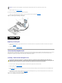 31
31
-
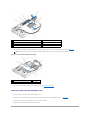 32
32
-
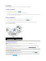 33
33
-
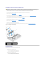 34
34
-
 35
35
-
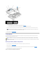 36
36
-
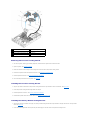 37
37
-
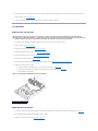 38
38
-
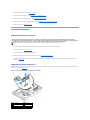 39
39
-
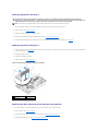 40
40
-
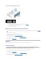 41
41
-
 42
42
-
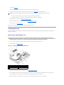 43
43
-
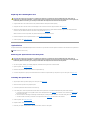 44
44
-
 45
45
-
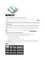 46
46
-
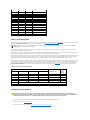 47
47
-
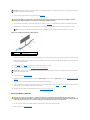 48
48
-
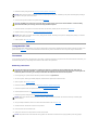 49
49
-
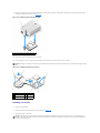 50
50
-
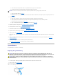 51
51
-
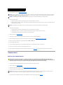 52
52
-
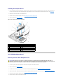 53
53
-
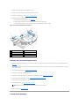 54
54
-
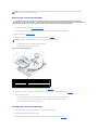 55
55
-
 56
56
-
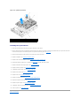 57
57
-
 58
58
-
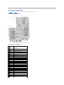 59
59
-
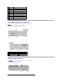 60
60
-
 61
61
-
 62
62
-
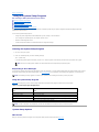 63
63
-
 64
64
-
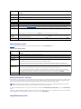 65
65
-
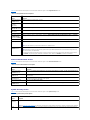 66
66
-
 67
67
-
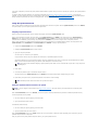 68
68
-
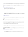 69
69
-
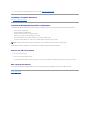 70
70
-
 71
71
-
 72
72
-
 73
73
-
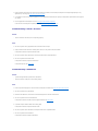 74
74
-
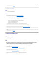 75
75
-
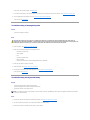 76
76
-
 77
77
-
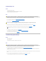 78
78
-
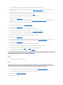 79
79
-
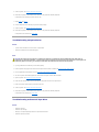 80
80
-
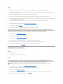 81
81
-
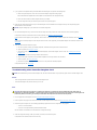 82
82
-
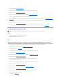 83
83
-
 84
84


Ask a question and I''ll find the answer in the document
Finding information in a document is now easier with AI
Related papers
-
Dell PowerEdge 1950 User manual
-
-
-
-
-
Dell PowerVault DP100 Owner's manual
-
Dell PowerEdge 2970 Owner's manual
-
Dell PowerEdge 860 Owner's manual
-
-
Other documents
-
Contour RollerMouse Red Owner's manual
-
Bull NovaScale R450 F2 Hardware Owner's manual
-
-
APC Replacement Battery Cartridge #22 User manual
-
HP RP3 Reference guide
-
 IESC ISR2500-6 User manual
-
NCR 7649-K021 Kit Instructions
-
Seagate User guide
-
 Rice Lake 71743 Installation guide
-
InWin Cables 4.0 User manual

