Page is loading ...

This manual must only be used by a qualified heating installer/service technician. Read all instructions, includ-
ing this manual and all other information shipped with the boiler, before installing. Perform steps in the order
given. Failure to comply could result in severe personal injury, death or substantial property damage.
• Installation
• Startup
• Maintenance
• Parts
Product Manual
Part number 635-500-156/0113
Companion
Water Heater
for WM97+ Gas-Fired Boilers
High Performance
Companion Water Heater
(Boiler sold separately)
®

CWH companion water heater — Product Manual
Contents
WM97+ Boiler with Companion Water Heater (CWH) 3
WM97+ Boiler . . . . . . . . . . . . . . . . . . . . . . . . . . . . 3
Companion Water Heater (CWH) . . . . . . . . . . . . . . . . . 3
Please read before proceeding 4
When servicing water heater . . . . . . . . . . . . . . . . . . . . 4
Operating restrictions . . . . . . . . . . . . . . . . . . . . . . . . 4
Boiler water restrictions . . . . . . . . . . . . . . . . . . . . . . . 4
Location . . . . . . . . . . . . . . . . . . . . . . . . . . . . . . . 4
Pre-installation 5
Codes . . . . . . . . . . . . . . . . . . . . . . . . . . . . . . . . . 5
CSA Low Lead Content Only certification . . . . . . . . . . . . . 5
Code restrictions . . . . . . . . . . . . . . . . . . . . . . . . . . . 5
Clearances and placement. . . . . . . . . . . . . . . . . . . . . . 5
Domestic water piping requirements. . . . . . . . . . . . . . . . 6
Water heater operating restrictions. . . . . . . . . . . . . . . . . 6
Boiler water restrictions . . . . . . . . . . . . . . . . . . . . . . . 6
Adjusting leveling legs . . . . . . . . . . . . . . . . . . . . . . . . 6
Alignment of CWH under the boiler. . . . . . . . . . . . . . . . 6
Hot Water Can Scald! . . . . . . . . . . . . . . . . . . . . . . . . 6
CWH Mixing valve 7
Mixing valve must be installed . . . . . . . . . . . . . . . . . . . 7
CWH orientation . . . . . . . . . . . . . . . . . . . . . . . . . . 7
Mixing valve installation and adjustment . . . . . . . . . . . . . 7
Domestic water piping 8
Piping overview . . . . . . . . . . . . . . . . . . . . . . . . . . . 8
Recirculation (if used) 10
Maintaining domestic water temperature in the supply piping . 10
Time delay at fixtures . . . . . . . . . . . . . . . . . . . . . . . . 10
Balancing . . . . . . . . . . . . . . . . . . . . . . . . . . . . . . .10
Components required . . . . . . . . . . . . . . . . . . . . . . . .10
Connecting to the water heater . . . . . . . . . . . . . . . . . . .11
Components (see Figure 10) . . . . . . . . . . . . . . . . . . . . 11
Operation. . . . . . . . . . . . . . . . . . . . . . . . . . . . . . . 11
Boiler/CWH piping — 70 or 110 / Right-side mixing valve 12
CONNECTIONS TO BOILER AND SYSTEM . . . . . . . . . . 12
CWH circulator mounting . . . . . . . . . . . . . . . . . . . . . 13
Boiler water connections . . . . . . . . . . . . . . . . . . . . . . 13
Boiler/CWH piping — 70 or 110 / Left-side mixing valve 14
CONNECTIONS TO BOILER AND SYSTEM . . . . . . . . . . 14
CWH circulator mounting . . . . . . . . . . . . . . . . . . . . . 15
Boiler water connections . . . . . . . . . . . . . . . . . . . . . . 15
Boiler/CWH piping — 155 / Right-side mixing valve 16
CONNECTIONS TO BOILER AND SYSTEM . . . . . . . . . . 16
CWH circulator mounting . . . . . . . . . . . . . . . . . . . . . 17
Boiler water connections . . . . . . . . . . . . . . . . . . . . . . 17
Boiler/CWH piping — 155 / Left-side mixing valve 18
CONNECTIONS TO BOILER AND SYSTEM . . . . . . . . . . 18
CWH circulator mounting . . . . . . . . . . . . . . . . . . . . . 19
Boiler water connections . . . . . . . . . . . . . . . . . . . . . . 19
Wiring 20
Connect circulator and sensor harnesses. . . . . . . . . . . . . . 20
Water heater filling and start-up 21
Boiler water restrictions . . . . . . . . . . . . . . . . . . . . . . . 21
Filling the domestic water tank . . . . . . . . . . . . . . . . . . .21
Start-up checklist . . . . . . . . . . . . . . . . . . . . . . . . . . 21
WM97+ control set-up . . . . . . . . . . . . . . . . . . . . . . . 21
Verify operation . . . . . . . . . . . . . . . . . . . . . . . . . . . 21
Homeowner instruction. . . . . . . . . . . . . . . . . . . . . . . 21
CWH control quick set-up 22
Water heater maintenance 23
ANNUAL maintenance . . . . . . . . . . . . . . . . . . . . . . .23
Shutdown procedure . . . . . . . . . . . . . . . . . . . . . . . . 23
WM97+ Control settings — Advanced 24
DHW SETTINGS . . . . . . . . . . . . . . . . . . . . . . . . . . 25
DHW PERFORMANCE: . . . . . . . . . . . . . . . . . . . . . . 25
TANK STORAGE TEMPERATURE: . . . . . . . . . . . . . . . .25
MAX RUN TIME . . . . . . . . . . . . . . . . . . . . . . . . . . 25
ADJUST SCHEDULES (WEEKDAYS / WEEKENDS) . . . . . .25
ADVANCED SETUP: . . . . . . . . . . . . . . . . . . . . . . . . 25
Troubleshooting 29
Troubleshooting procedures . . . . . . . . . . . . . . . . . . . . 29
Preparation for troubleshooting . . . . . . . . . . . . . . . . . . 29
Replacement parts 39
Determine required temperature rise 40
Ratings 41
AHRI ratings 42
Dimensions 43
Page Page
Part number 635-500-156/0113
2

CWH companion water heater — Product Manual
WM97+ Boiler with Companion Water Heater (CWH)
WM97+
Boiler
(Model 70/110 shown)
(Shown with typical
external pipe routing —
pipes can be routed out
either side or both sides)
WM97+
Companion
Water Heater
WM97+ Boiler
Installation summary
Follow the boiler manual, this manual, and all
applicable codes. Installation consists of the
following:
• Mount boiler on the wall.
• Mount boiler at height shown in the boiler
manual and make sure clearance is provided
on right or left side for piping as directed.
• Install gas piping, condensate trap and con-
densate piping, positioned to route out the
side opening(s) in the piping access panel.
• Set the WM97+ boiler control for the desired
operation of the CWH.
• Perform all start-up tests to verify proper
operation of boiler and water heater.
Companion Water Heater
(CWH)
Installation summary
Follow the boiler manual, this manual, and all
applicable codes. Installation consists of the
following:
• Position the CWH under the boiler and check
fit of the piping access cover. Orient with
DHW connections on either side by rotating
the water heater 180°.
• Mount the CWH circulator, street tee, bush-
ing and drain valve.
• Connect the flexible lines from the circulator
and CWH boiler connections to the boiler
domestic water connections on the bottom
of the boiler.
• Mount the mixing valve assembly supplied
with the CWH, following the mixing valve
instructions provided with the valve kit.
• Install and pipe the T&P relief valve in the
CWH.
• Connect from the mixing valve and cold
water tee to the domestic water system.
• Connect the plug-in wire harnesses from the
CWH to the harnesses in the boiler.
• Set the mixing valve and instruct the owner
in operation of the CWH and boiler.
Part number 635-500-156/0113
3

CWH companion water heater — Product Manual
Please read before proceeding
Failure to adhere to the guidelines on this page can
result in severe personal injury, death or substantial
property damage.
Read all instructions before installing. Failure to follow all instruc-
tions in proper order can cause severe personal injury, death or
substantial property damage.
When servicing water heater
• To avoid electric shock, disconnect electrical supply before
performing maintenance.
• To avoid severe burns, allow water heater to cool before per-
forming maintenance.
Operating restrictions
• Read precautions on page 6.
• Maximum boiler water temperature — 200°F.
• Maximum working pressure for tank — 150 PSIG.
• Water chemistry limits:
• hardness — less than 6 grains/gal.
• pH — above 6 and less than 8.
• chlorides — less than 200 ppm.
• A water softener in the domestic water system is acceptable.
• Filtration — If domestic water tends to contain sediment,
provide filtration equipment as needed to remove sediment.
Boiler water restrictions
• Thoroughly flush the boiler system (without water heater
connected) to remove sediment.
• The water heater heat exchanger can be damaged by build-up
or corrosion due to sediment.
• Boiler water (including additives) must be practically non-
toxic, having toxicity rating or class of 1, as listed in Clinical
Toxicology of Commercial Products. Sentinel products sup-
plied for the WM97+ are acceptable.
• If antifreeze is used in boiler system:
• Local codes may require a backflow preventer on cold
water supply line.
• Use antifreeze specifically intended for hydronic heating
systems. Inhibited propylene glycol is recommended.
• Follow boiler manual instructions for antifreeze usage.
• Do not use automotive, ethylene glycol or petroleum-
based antifreeze. Do not use any undiluted antifreeze.
Location
• This water heater is not intended for outdoor installation.
• Install the water heater so if the tank or any connections
should leak, the water flow will not cause damage to area
near water heater, or to lower floors of structure. When such
locations cannot be avoided, install a suitable drain pan under
water heater. Drain pans are available at your local plumbing
supply store.
• This product is designed for vertical installation only.
When calling or writing about the water
heater — Please have the water heater
serial number from the serial number
label, located on the side of the water
heater, on to the rating plate.
Any claims for damage or shortage in
shipment must be filed immediately
against the transportation company by
the consignee.
Hazard definitions
The following defined terms are used throughout this
manual to bring attention to the presence of hazards
of various risk levels or to important information
concerning the life of the product.
Indicates presence of hazards that will
cause severe personal injury, death or
substantial property damage.
Indicates presence of hazards that can
cause severe personal injury, death or
substantial property damage.
Indicates presence of hazards that will
or can cause minor personal injury or
property damage.
Indicates special instructions on installa-
tion, operation or maintenance that are
important but not related to personal
injury or property damage.
This manual provides installation and
operation guidelines for the Weil-
McLain CWH indirect water heater.
The installer is responsible for ensuring
that the installation complies with this
manual, the boiler manual and all ap-
plicable codes.
Massachusetts installations — The
water heater must be installed by a li-
censed plumber. The installation must
follow all Massachusetts code require-
ments. The domestic water piping must
comply with the piping shown in this
manual. See “Domestic water piping,”
page 8, for details and code requirements.
Part number 635-500-156/0113
4

CWH companion water heater — Product Manual
Pre-installation
The 18-inch mixing valve side clearance
below is MANDATORY
. The 1½” clearance
on the opposite side is strongly recommended
(a smaller clearance will make servicing more
difficult). ADDITIONAL clearance may be
needed if piping is routed on both sides of
the boiler/water heater.
Figure 1
Clearance required (in addition to
clearances specified in the WM97+
manual) — right-mounted mixing valve
1½” min this side 18” min this side
Figure 2 Clearance required (in addition to
clearances specified in the WM97+
manual) — left-mounted mixing valve
1½” min this side18” min this side
Figure 3 Align water heater under boiler as needed
for the piping access panel to fit in place
Piping
access
panel
Codes
1. Installation must conform with instructions in this manual and,
where applicable:
• local, state, provincial, and national codes, laws, regulations
and ordinances.
• in Canada — B149.1 or B149.2 Installation Code.
2. CWH water heaters are exempt from ASME Section VIII, Division
1 Code construction per Interpretation VIII-1-86-136. Check with
local codes for applicability.
3. Where recommendations in this manual differ from local or na-
tional codes, local or national codes take precedence.
CSA Low Lead Content Only certification
1. This product has been certified by CSA to Class 6853 01 — Low
Lead Content Certification Program — Plumbing Products.
2. Applicable requirements:
a. NSF/ANSI 372-2010 Drinking water system components –
Lead Content.
b. California Health and Safety Code 116875 (known as AB-
1953-2006).
c. Louisiana House Bill HB.471, Louisiana’s Lead reduction Law.
d. Vermont Act No. 193 - 2008 Consumer Products Prohibition
against Lead.
e. Maryland House Bill 372 [Statute 12- 605], Business Occupa-
tions and Professionals – Plumbers – Lead Free Materials.
Code restrictions
National Standard Plumbing Code
1. Single-wall heat exchanger in water heater complies with National
Standard Plumbing Code, provided that:
a. Boiler water (including additives) is practically non-toxic, hav-
ing toxicity rating or class of 1, as listed in Clinical Toxicology
of Commercial Products, and
b. Boiler water pressure is limited to maximum 30 PSIG by ap-
proved relief valve.
Uniform Plumbing Code
1. Single-wall heat exchangers are permitted if they satisfy all of the
following requirements —
a. The heat transfer medium is potable water or contains only
substances which are recognized as safe by the U. S. Food and
Drug Administration.
b. The pressure of the heat transfer medium is maintained less
than the normal minimum operating pressure of the potable
water system.
c. The equipment is permanently labeled to indicate that only
additives recognized as safe by the FDA shall be used in the
heat transfer medium.
2. Other heat exchanger designs may be permitted where approved
by the Administrative Authority.
Clearances and placement
1. The CWH must be mounted under the WM97+ boiler, with the
boiler installed to meet all required clearances in the boiler manual.
2. IN ADDITION
,
provide 18 inches clearance minimum
on the
mixing valve side.
3. Read and comply with “Location,” page 4 of this manual.
Part number 635-500-156/0113
5

CWH companion water heater — Product Manual
Pre-installation
(continued)
Hot Water Can Scald!
• Water heated to temperature for clothes washing,
dish washing and other sanitizing needs can scald
and cause permanent injury.
• Children, elderly, and infirm or physically handi-
capped persons are more likely to be permanently
injured by hot water. Never leave them unattended
in bathtub or shower. Never allow small children to
use a hot water tap or draw their own bath.
• If anyone using hot water in the building fits
the above description, or if state laws or local
codes require certain water temperatures at hot
water taps, you must take special precautions:
• Use lowest possible temperature setting.
• Install a thermostatic protective device at
each point of use in addition to the mixing
valve installed at the water heater.
• Water passing out of drain valves may be extremely
hot. To avoid injury:
• Make sure all connections are tight.
• Direct water flow away from any person.
For all applications:
Protection must be taken against exces-
sive temperature and pressure! — Install a
temperature & pressure (T&P) relief valve
(like that provided with the water heater) and
thermostatic mixing valve (like that provided
with the water heater). In addition, a thermo-
static protective device at each point of use
may also be necessary.
Domestic water piping requirements
1. Install unions on all piping for easy removal of water heater.
2. Use
dielectric unions or couplings to protect hot and cold water
fittings from corrosion when connecting dissimilar materials such
as copper and galvanized iron pipe.
3.
When the supply pressure is higher than 70 PSIG, install a pres-
sure reducing valve on cold water supply line to prevent water loss
through T&P relief valve. A thermal expansion tank is also required.
Studies have indicated that dangerous bacteria,
including
legionella pneumophila, can form in
the potable water distribution system if certain
minimum water temperatures are not main-
tained. Contact your local health department for
more information.
Water heater operating restrictions
1. Read the operating limits under “Operating restrictions,” page 4.
Boiler water restrictions
1. Read the WARNINGS under “Boiler water restrictions,” page 4.
Adjusting leveling legs
1. Before installing any piping, level the CWH.
2. Carefully tip the water heater onto its side.
3. Screw in the leveling legs.
4. Return the water heater to the upright position and set in place.
5. Adjust the legs as necessary to level the water heater.
Alignment of CWH under the boiler
1. When in place, there must be sufficient room to route all required
piping connections to the water heater and the WM97+ boiler.
2. Verify the fit-up of the piping access panel — the CWH must be
directly underneath the WM97+ boiler. Test fit the access panel
to be sure before installing piping. Panel must be unobstructed.
Part number 635-500-156/0113
6

CWH companion water heater — Product Manual
DANGER
Mixing valve must be installed
Follow all instructions in this manual and in the mix-
ing valve manufacturer’s literature provided with the
water heater to install the mixing valve.
CWH orientation
1. The CWH can be installed with its domestic water inlet/outlet
connections on the right or on the left.
2. Place the CWH on the floor below the WM97+ boiler.
3. The CWH circulator must be installed on the top left front boiler
water connection in all applications. See details in this manual for
piping requirements and circulator orientation.
Mixing valve installation and adjustment
1. See Figure 4 (right side mounting) or Figure 5 (left side mounting).
2. The mixing valve kit is shipped loose with the CWH and must be
field installed.
The mixing valve kit illustrated in this manual is the Hon-
eywell AMX302TLF. If another mixing valve is used as a
replacement later, it must provide all of the functionality
of the AMX302TLF.
3. The mixing valve kit includes the mixing valve (upper fitting), cold
water tee and flex connector line.
Follow the instructions in the mixing valve manufac-
turer’s manual supplied with the mixing valve kit
. Be
sure to set the mixed water temperature as directed and
to instruct the homeowner. See warnings and danger
information on page 6. Failure to install the correct wa-
ter temperature control devices and properly set water
temperature can result in severe personal injury or death.
DO NOT attempt to solder any connection directly
to the mixing valve or return fitting.
This will damage
the mixing valve or return fitting, resulting in possible
failure to properly control water temperature supplied
to the DHW system. Solder only to adapter fittings that
are NOT connected to the valve or return fitting.
CWH Mixing valve
The mixing valve assembly shown below
and in the piping diagrams throughout this
manual are for the Honeywell AMX302TLF.
Figure 4 Mixing valve assembly, CWH connections
on right side
Figure 5 Mixing valve assembly, CWH rotated,
connections on left
Part number 635-500-156/0113
7

CWH companion water heater — Product Manual
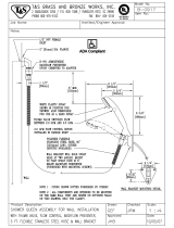
Figure 6 DHW piping (shown with WM97+155, right-side piping, with Honeywell AMX302TLF mixing valve assembly)
Domestic water piping
Piping overview
THERMAL EXPANSION TANK — If a backflow
preventer, check valve, or pressure reducing valve
is piped on cold water inlet of water heater, you
must install an expansion tank on cold water sup-
ply line to prevent normal thermal expansion from
repeatedly forcing open T&P relief valve. The T&P
relief valve is not intended for constant duty, such
as relief of pressure due to repeated normal system
expansion. Refer to expansion tank manufacturer’s
instructions for proper sizing. Failure to comply
could result in severe personal injury, death or
substantial property damage.
General applications
1. See Figure 6 — This domestic water piping configuration
can be used in most cases, except where local codes require
special components or piping not illustrated.
2. See next page for legend.
3. Some codes may require the items listed as optional, such as
a vacuum breaker on the inlet line, or recirculation piping.
4. Recirculation, when required — See page 10 for recirculation
piping information.
Massachusetts applications
1. For Massachusetts code applications, or as required else-
where by local codes, install the following options.
a. Thermal siphon on domestic water inlet and outlet.
b. Vacuum breaker on domestic water inlet line.
c. Recirculation —
Massachusetts code applications
require recirculation piping or heat-traced piping if the
distance from the water heater to the furthest fixture
exceeds 100 feet.
Part number 635-500-156/0113
8

CWH companion water heater — Product Manual
Domestic water piping
(continued)
LEGEND for Figure 6, page 8
Domestic water supplied to fixtures that could pose
an injury hazard due to high temperature, such as
showers and faucets, should be equipped with a
temperature regulating device, such as an anti-scald
mixing valve
.
When the supply pressure is higher than 70 PSIG,
install a pressure reducing valve on cold water
supply line to prevent water loss through T&P relief
valve. A thermal expansion tank is also required.
This symbol, where used in this manual, indicates the
item is required by Massachusetts code.
This symbol indicates the item is optional, unless
required by applicable codes.
1
Companion Water Heater (CWH) — stainless steel heat
exchanger and tank with integral foam enclosure — shown with
WM97+155 boiler and right-side piping connections — piping can
be routed either side or both, depending on clearances (see page7
for instructions to mount and connect the mixing valve supplied
with the CWH)
2 WM97+ boiler — Model WM97+70, 110 or 155 (155 shown)
3 Domestic water cold inlet
4 DHW mixed outlet from mixing valve
5 Mixing valve cold water tee (supplied with mixing valve)
5a Mixing valve flexible metal connector (supplied with
mixing valve)
6 Honeywell mixing valve — Figure 6, page 8 shows
the Honeywell AMX302TLF mixing valve assembly — refer to
mixing valve literature supplied with the CWH — AMX302TLF is
ASSE 1017 compliant.
6b
6c
6e
6d
6f
6a
6a Mixed temperature adjustment knob —
DO NOT adjust this knob without following instructions supplied
with mixing valve assembly.
6b Mixing valve hot water inlet port (HOT) — ¾” FNPT
— Connects directly to CWH hot water outlet pipe
6c Mixing valve mixed water outlet port (MIX) — ¾”
MNPT — domestic hot water system supply connection
6d Mixing valve recirculation port (R) — ½” FNPT —
Recirculation connection — Follow mixing valve instructions and
information beginning on page 10
of this manual. (Requires
3/8” Allen wrench to remove.)
6e
Mixing valve cold water inlet port (COLD) — ½” are
tting — Assemble mixing valve components (items5, 5a and6)
according to the instructions supplied with the mixing valve.
6f (AH) — DO NOT USE — e water from this
port is not regulated by the mixing valve.
7 T&P relief valve (mounted in top of CWH) — supplied
with CWH
• Use only the T&P valve supplied with the water heater.
See Replacement parts for part number.
• Install the T&P relief valve as shown in the piping con-
nection instructions in this manual.
8
T&P relief valve discharge piping —
• Must be made of material serviceable for temperatures
of 250°F or greater.
• Must be directed so that hot water flows away from all
persons.
• Must be directed to a suitable place for disposal.
• Must be installed so as to allow complete draining of the
T&P relief valve and discharge line.
• Must not be excessively long.
• Must not be directly connected to a drain — terminate
discharge piping within 6” from floor — refer to local
codes.
• Must not be plugged, reduced or restricted or terminated
with a threaded end.
• Must not be subjected to freezing.
Do not install any valve between the T&P relief
valve and CWH connection, or on T&P relief valve
discharge piping. Do not plug T&P relief valve or its
discharge piping. Improper placement and piping
of T&P relief valve can cause severe personal injury,
death or substantial property damage.
• Pipe from relief valve to floor drain, if available.
9
Domestic mixed water supply to system
10 Thermal expansion tank —
• REQUIRED if cold water line is equipped with a backflow
preventer or pressure reducing valve — see EXPANSION
TANK WARNING
on page 8.
11
DHW drain valve — supplied with CWH
• Install the drain valve on the cold water inlet tee (port
AC) as shown.
12
Isolation valves
13 Cold domestic water supply
14 Backflow preventer — — — (required
for Commonwealth of Massachusetts)
15 Pressure reducing valve —
• REQUIRED when the supply pressure is higher than
70 PSIG — A thermal expansion tank is also required.
16
Unions
17 Vacuum breaker —
18 Shock arrester —
Dishwashers, clothes washers, and fast-closing positive
shutoff valves incorporated in the system all contrib-
ute to creating water shock. Install a water hammer
arrester to prevent damage to pipes and appliances.
See control manufacturer’s instructions for applica-
tion and installation.
19
Heat trap loops (12” minimum) —
Part number 635-500-156/0113
9

CWH companion water heater — Product Manual
Figure 7 Time lag to obtain hot water at fixture for
branch lengths of 10 and 25 feet (ASPE
Domestic Water Heating Design Manual)
Time in seconds required to get hot water at fixture
Fixture flow rate (GPM) 0.5 1.5 2.5 4.0
Piping length (feet) - 10 25 10 25 10 25 10 25
Copper pipe ½” 25 63 8 21 5 13 3 8
¾” 48 119 16 40 10 24 6 15
Steel pipe ½” 63 157 21 52 13 31 8 20
¾” 91 228 30 76 18 46 11 28
CPVC pipe ½” 64 159 21 53 13 62 8 20
¾” 95 238 32 79 19 48 12 30
NOTE: Select branch size and length for less than 31 seconds
delay.
Figure 8 Recirculation components
Massachusetts code applications require recirculation
piping or heat-traced piping if the distance from the
water heater to the furthest fixture exceeds 100 feet.
Maintaining domestic water temperature
in the supply piping
1. Recirculation is used to reduce wait time for water use, to minimize
hot water and energy waste caused during the waiting period, and
to prevent degradation of the system supply water temperature.
ASPE recommends recirculation when the distance from the water
heater to the furthest fixture exceeds 100 feet or the time lag for
hot water to reach a fixture(s) exceeds 30 seconds.
2. Consult local codes and American Society of Plumbing Engineers
(ASPE) Domestic Water Heating Design Manual, 1998, for further
information.
Time delay at fixtures
1. Figure 7 is from the ASPE Domestic Water Heating Design Manual,
1998. It shows the time required for usable hot water to arrive at a
fixture based on the fixture flow rate (available from industry and
manufacturer’s data) and the length and diameter of the dead-end
branch pipe supplying the fixture.
2. The time lag should generally not exceed 30 seconds.
3. For residential and office applications, the owner may prefer a
limit of 10 seconds.
4. You can use Figure 7 as a guide to determining the location of
circulation return lines relative to fixtures.
Balancing
1. When multiple branches are connected to the supply piping, each
branch must be connected to the recirculation system.
a. At each of these connections to the return piping, install shutoff
valves, a flow metering device, check valve and a strainer as
shown in Figure 8.
b. Check local codes for specific installation requirements.
2. These branches must be balanced to prevent pipe erosion and
unacceptable time delays at some fixtures.
3. Balancing options include circuit setters, memory stop valves or
factory preset devices (with flow metering provision in the piping).
Components required
1. For residential applications, consult circulator manufacturer’s
data for circulator selection and additional components required.
2. On most commercial systems, install the devices shown in Figure 8,
and any other devices or piping methods required by local codes.
a. The check valves are required to prevent fixtures from taking
hot water through the return lines.
b. Shutoff valves are needed to allow cleaning and replacing
balancing devices.
c. Include strainers to remove sediment which could damage the
circulator and / or affect the flow balancing devices.
Recirculation (if used)
Part number 635-500-156/0113
10

CWH companion water heater — Product Manual
Recirculation (if used)
(continued)
3. Size the circulator and piping based on the tempera-
ture drop allowed between the water available at the
water heater and the water delivered at the fixture.
a. The return piping will almost always be smaller
than the supply piping, but should never be
smaller than ½” to prevent problems with the
circulator.
4. Make provision for removal of air in all return lines.
Where the returns cannot be vented by topmost
fixtures in the system, install automatic air venting
at the top of the return piping.
Connecting to the water heater
1. Install the domestic water components as shown
in Figure 6, page 8.
2. See the following pages for piping between boiler
and water heater, boiler lower pipe routing and
CWH relief valve.
a. WM97+70 or 110 boiler:
Mixing valve on right side of CWH: page 12
Mixing valve on left side of CWH: page 14
b. WM97+155 boiler:
Mixing valve on right side of CWH: page 16
Mixing valve on left side of CWH: page 18
Components (see Figure 9)
Recirculation pump
1. Little flow is required to maintain a temperature
in the piping.
2. Size of pump depends on minimum flow require-
ments of the mixing valve.
3. Minimum flow rates of the mixing valve must be
maintained (minimum for Honeywell AMX302TLF
is 0.25 GPM).
Recirculation pump aquastat
1. Used to control the on-off position of the circula-
tor. Aquastat is set 5° to 10° lower than mixed water
outlet of the mixing valve.
2. The pump cannot run continuously — bypass
through the mixing valve will eventually allow the
temperature on the piping to climb to the water
heater temperature during draw periods.
Check valve
1. Assures the flow of water in one direction.
Operation
1. When temperature at recirculation pump aquastat
falls 10° below temperature to be maintained —
recirculation pump turns on.
2. When aquastat reaches temperature — Circulator
turns off.
Figure 9 Recirculation piping at mixing valve
Part number 635-500-156/0113
11

CWH companion water heater — Product Manual
CONNECTIONS TO BOILER
AND SYSTEM
The CWH can be placed with its DHW connec-
tions on the left side or on the right side (by
rotating the unit 180 degrees). This instruction
is for installations with the CHW with its DHW
connections on the RIGHT side. The boiler
shown must be either a model WM97+70 or
WM97+110.
1. Boiler water RETURN connection from CWH
2. Boiler water SUPPLY connection to CWH
3. Water heater T & P relief valve connection
T&P relief valve is shipped loose with the CWH for field
installation.
4. Upper tank temperature sensor
5. DHW supply and return connections on side
Follow instructions on page 7 to install the mixing valve that
is supplied with the CWH.
6. Boiler hot water SUPPLY to CWH
7. Boiler water RETURN from CWH
8. Gas supply connection to boiler
Installer must provide hard piping or flexible gas line between
boiler connection and gas line connection (item 20).
9. Condensate trap connection to boiler
10. CWH boiler water circulator
(shipped loose with CWH)
This circulator is shipped loose with the CWH. The circulator
flows boiler water through the internal heat exchanger coil.
The WM97+ boiler control cycles the circulator based on
domestic water demand.
The circulator must be installed in the location and flow di-
rection shown on the next page. Otherwise, the water heater
will not perform correctly.
The circulator is 3-speed with an integral flow/check valve.
The circulator speed MUST be set at “1(LO)” when
connected to a WM97+70 or 110. The circulator
speed MUST be set at “3(HI)” when connected to
a WM97+155.
11. Circulator mounting hardware
(shipped loose with
CWH)
The lower mounting flange, bolts, nuts and gaskets are
shipped loose for installation with the circulator. Note that
the lower flange must be rotated 10 degrees clockwise relative
to the front face of the CWH.
12. Upper circulator flange/boiler water connection
(shipped loose with CWH)
This fitting is shipped loose for field installation in the loca-
tion and position shown on the opposite page.
13. Flexible boiler water RETURN line (either of two
flexible lines shipped loose with the CWH)
Two 1-inch flexible stainless steel hoses are shipped loose for
field installation. Use one hose each for boiler water CWH
supply and return connections. Make sure a gasket is placed in
each the hex fittings on the hose ends. No pipe dope or tape is
needed. DO NOT over-tighten — gasket would be damaged.
14. Service tee, 1” (shipped loose with CWH)
Install the service tee in the location shown in this manual
to provide location for the boiler drain valve (item 16). A
bushing, 1”x¾” NPT, is supplied for mounting the boiler
drain valve as shown in this manual.
15. Bushing for mounting hose bibb drain valve
(shipped loose with CWH)
Install the 1” x ¾” bushing in the service tee.
16. Boiler drain valve, ¾” (shipped loose with boiler)
This valve is shipped loose with the WM97+ boiler. It must
be located as shown on the opposite page when the boiler is
connected to a CWH.
17. Flexible boiler water SUPPLY line (either of two
flexible lines shipped loose with the CWH)
Two 1-inch flexible stainless steel hoses are shipped loose for
field installation. Use one hose each for boiler water CWH
supply and return connections. Make sure a gasket is placed in
each the hex fittings on the hose ends. No pipe dope or tape is
needed. DO NOT over-tighten — gasket would be damaged.
18. T & P relief valve (shipped loose with CWH)
T & P relief valve is shipped loose with the CWH for field
installation in the location shown on the next page.
19. Relief valve discharge piping
The relief valve outlet MUST be piped to a safe discharge
location, following all local codes. See page 9 for instructions
and requirements.
20. Gas connection with manual gas valve, union
and drip leg (gas valve is shipped loose with boiler)
The manual gas valve shown on the opposite page is shipped
loose for field installation. Follow all instructions in the
WM97+ Boiler manual for sizing and installing gas connec-
tions. The manual gas valve and piping shown as item 20 must
be installed OUTSIDE the piping access panel and braced/
supported from the wall or other structure. Orient the piping
for best routing through one of the piping access panel sides.
21. To building gas supply
22. Condensate trap assembly
(shipped loose with boiler)
The trap assembly is shipped loose for field assembly and
installation. Follow WM97+boiler manual instructions for
trap assembly and installation. Orient the trap for best routing
of the condensate drain line through the right or left opening
in the piping access cover.
23. Connect to condensate drain piping
Follow all WM97+ Boiler manual instructions for connecting
condensate drain piping.
Boiler/CWH piping — 70 or 110 / Right-side mixing valve
Part number 635-500-156/0113
12

CWH companion water heater — Product Manual
Boiler/CWH piping — 70 or 110 / Right-side mixing valve
(cont.)
Figure 10 Typical piping for WM97+70 or
110 — CWH installed with right-
side mixing valve
All piping must comply
with the instructions in the
WM97+ Boiler manual.
Piping can be routed out ei-
ther side or both sides of the
CWH piping access cover.
The example shown here is
just one possibility.
CWH circulator mounting
• The circulator MUST be mounted in
the position shown — pumping out
of the water heater toward the boiler
DHW return.
This is required to flow
boiler water through the water heater in
the correct direction.
• Rotate the lower circulator flange adapt-
er 10° clockwise (looking down on the
flange). This is necessary to ensure the
circulator electrical housing will clear the
inside of the piping access cover.
Boiler water connections
• The CWH boiler water supply and
return lines MUST be routed to the
boiler connections as shown to en-
sure proper flow.
Part number 635-500-156/0113
13

CWH companion water heater — Product Manual
Boiler/CWH piping — 70 or 110 / Left-side mixing valve
CONNECTIONS TO BOILER
AND SYSTEM
The CWH can be placed with its DHW connec-
tions on the left side or on the right side (by
rotating the unit 180 degrees). This instruction
is for installations with the CHW with its DHW
connections on the LEFT side. The boiler
shown must be either a model WM97+70 or
WM97+110.
1. Boiler water RETURN connection from CWH
2. Boiler water SUPPLY connection to CWH
3. Water heater T & P relief valve connection
T&P relief valve is shipped loose with the CWH for field
installation.
4. Upper tank temperature sensor
5. DHW supply and return connections on side
Follow instructions on page 7 to install the mixing valve that
is supplied with the CWH.
6. Boiler hot water SUPPLY to CWH
7. Boiler water RETURN from CWH
8. Gas supply connection to boiler
Installer must provide hard piping or flexible gas line between
boiler connection and gas line connection (item 20).
9. Condensate trap connection to boiler
10. CWH boiler water circulator
(shipped loose with CWH)
This circulator is shipped loose with the CWH. The circulator
flows boiler water through the internal heat exchanger coil.
The WM97+ boiler control cycles the circulator based on
domestic water demand.
The circulator must be installed in the location and flow di-
rection shown on the next page. Otherwise, the water heater
will not perform correctly.
The circulator is 3-speed with an integral flow/check valve.
The circulator speed MUST be set at “1(LO)” when
connected to a WM97+70 or 110. The circulator
speed MUST be set at “3(HI)” when connected to
a WM97+155.
11. Circulator mounting hardware
(shipped loose with
CWH)
The lower mounting flange, bolts, nuts and gaskets are
shipped loose for installation with the circulator. Note that
the lower flange must be rotated 10 degrees counterclockwise
relative to the front face of the CWH.
12. Upper circulator flange/boiler water connection
(shipped loose with CWH)
This fitting is shipped loose for field installation in the loca-
tion and position shown on the opposite page.
13. Flexible boiler water RETURN line (either of two
flexible lines shipped loose with the CWH)
Two 1-inch flexible stainless steel hoses are shipped loose for
field installation. Use one hose each for boiler water CWH
supply and return connections. Make sure a gasket is placed in
each the hex fittings on the hose ends. No pipe dope or tape is
needed. DO NOT over-tighten — gasket would be damaged.
14. Service tee, 1” (shipped loose with CWH)
Install the service tee in the location shown in this manual
to provide location for the boiler drain valve (item 16). A
bushing, 1”x¾” NPT, is supplied for mounting the boiler
drain valve as shown in this manual.
15. Bushing for mounting hose bibb drain valve
(shipped loose with CWH)
Install the 1” x ¾” bushing in the service tee.
16. Boiler drain valve, ¾” (shipped loose with boiler)
This valve is shipped loose with the WM97+ boiler. It must
be located as shown on the opposite page when the boiler is
connected to a CWH.
17. Flexible boiler water SUPPLY line (either of two
flexible lines shipped loose with the CWH)
Two 1-inch flexible stainless steel hoses are shipped loose for
field installation. Use one hose each for boiler water CWH
supply and return connections. Make sure a gasket is placed in
each the hex fittings on the hose ends. No pipe dope or tape is
needed. DO NOT over-tighten — gasket would be damaged.
18. T & P relief valve (shipped loose with CWH)
T & P relief valve is shipped loose with the CWH for field
installation in the location shown on the next page.
19. Relief valve discharge piping
The relief valve outlet MUST be piped to a safe discharge
location, following all local codes. See page 9 for instructions
and requirements.
20. Gas connection with manual gas valve, union
and drip leg (gas valve is shipped loose with boiler)
The manual gas valve shown on the opposite page is shipped
loose for field installation. Follow all instructions in the
WM97+ Boiler manual for sizing and installing gas connec-
tions. The manual gas valve and piping shown as item 20 must
be installed OUTSIDE the piping access panel and braced/
supported from the wall or other structure. Orient the piping
for best routing through one of the piping access panel sides.
21. To building gas supply
22. Condensate trap assembly
(shipped loose with boiler)
The trap assembly is shipped loose for field assembly and
installation. Follow WM97+boiler manual instructions for
trap assembly and installation. Orient the trap for best routing
of the condensate drain line through the right or left opening
in the piping access cover.
23. Connect to condensate drain piping
Follow all WM97+ Boiler manual instructions for connecting
condensate drain piping.
Part number 635-500-156/0113
14

CWH companion water heater — Product Manual
Boiler/CWH piping — 70 or 110 / Left-side mixing valve
(cont.)
Figure 11 Typical piping for WM97+70 or
110 — CWH installed with left-
side mixing valve
All piping must comply
with the instructions in the
WM97+ Boiler manual.
Piping can be routed out ei-
ther side or both sides of the
CWH piping access cover.
The example shown here is
just one possibility.
CWH circulator mounting
• The circulator MUST be mounted in
the position shown — pumping out
of the boiler toward the CWH.
This is
required to flow boiler water through
the water heater in the correct direction.
• Rotate the lower circulator flange adapt-
er 10° counterclockwise (looking down
on the flange). This is necessary to ensure
the circulator electrical housing will clear
the inside of the piping access cover.
Boiler water connections
• The CWH boiler water supply and
return lines MUST be routed to the
boiler connections as shown to en-
sure proper flow.
Part number 635-500-156/0113
15

CWH companion water heater — Product Manual
Boiler/CWH piping — 155 / Right-side mixing valve
CONNECTIONS TO BOILER
AND SYSTEM
The CWH can be placed with its DHW connec-
tions on the left side or on the right side (by
rotating the unit 180 degrees). This instruction
is for installations with the CHW with its DHW
connections on the RIGHT side. The boiler
shown must be a model WM97+155.
1. Boiler water RETURN connection from CWH
2. Boiler water SUPPLY connection to CWH
3. Water heater T & P relief valve connection
T&P relief valve is shipped loose with the CWH for field
installation.
4. Upper tank temperature sensor
5. DHW supply and return connections on side
Follow instructions on page 7 to install the mixing valve that
is supplied with the CWH.
6. Boiler hot water SUPPLY to CWH
7. Boiler water RETURN from CWH
8. Gas supply connection to boiler
Installer must provide hard piping or flexible gas line between
boiler connection and gas line connection (item 20).
9. Condensate trap connection to boiler
10. CWH boiler water circulator
(shipped loose with CWH)
This circulator is shipped loose with the CWH. The circulator
flows boiler water through the internal heat exchanger coil.
The WM97+ boiler control cycles the circulator based on
domestic water demand.
The circulator must be installed in the location and flow di-
rection shown on the next page. Otherwise, the water heater
will not perform correctly.
The circulator is 3-speed with an integral flow/check valve.
The circulator speed MUST be set at “1(LO)” when
connected to a WM97+70 or 110. The circulator
speed MUST be set at “3(HI)” when connected to
a WM97+155.
11. Circulator mounting hardware
(shipped loose with
CWH)
The lower mounting flange, bolts, nuts and gaskets are
shipped loose for installation with the circulator. Note that
the lower flange must be rotated 10 degrees clockwise rela-
tive to the front face of the CWH. Note that the lower flange
must be rotated 10 degrees clockwise relative to the front
face of the CWH.
12. Upper circulator flange/boiler water connection
(shipped loose with CWH)
This fitting is shipped loose for field installation in the loca-
tion and position shown on the opposite page.
13. Flexible boiler water RETURN line (either of two
flexible lines shipped loose with the CWH)
Two 1-inch flexible stainless steel hoses are shipped loose for
field installation. Use one hose each for boiler water CWH
supply and return connections. Make sure a gasket is placed in
each the hex fittings on the hose ends. No pipe dope or tape is
needed. DO NOT over-tighten — gasket would be damaged.
14. Service tee, 1” (shipped loose with CWH)
Install the service tee in the location shown in this manual
to provide location for the boiler drain valve (item 16). A
bushing, 1”x¾” NPT, is supplied for mounting the boiler
drain valve as shown in this manual.
15. Bushing for mounting hose bibb drain valve
(shipped loose with CWH)
Install the 1” x ¾” bushing in the service tee.
16. Boiler drain valve, ¾” (shipped loose with boiler)
This valve is shipped loose with the WM97+ boiler. It must
be located as shown on the opposite page when the boiler is
connected to a CWH.
17. Flexible boiler water SUPPLY line (either of two
flexible lines shipped loose with the CWH)
Two 1-inch flexible stainless steel hoses are shipped loose for
field installation. Use one hose each for boiler water CWH
supply and return connections. Make sure a gasket is placed in
each the hex fittings on the hose ends. No pipe dope or tape is
needed. DO NOT over-tighten — gasket would be damaged.
18. T & P relief valve (shipped loose with CWH)
T & P relief valve is shipped loose with the CWH for field
installation in the location shown on the next page.
19. Relief valve discharge piping
The relief valve outlet MUST be piped to a safe discharge
location, following all local codes. See page 9 for instructions
and requirements.
20. Gas connection with manual gas valve, union
and drip leg (gas valve is shipped loose with boiler)
The manual gas valve shown on the opposite page is shipped
loose for field installation. Follow all instructions in the
WM97+ Boiler manual for sizing and installing gas connec-
tions. The manual gas valve and piping shown as item 20 must
be installed OUTSIDE the piping access panel and braced/
supported from the wall or other structure. Orient the piping
for best routing through one of the piping access panel sides.
21. To building gas supply
22. Condensate trap assembly
(shipped loose with boiler)
The trap assembly is shipped loose for field assembly and
installation. Follow WM97+boiler manual instructions for
trap assembly and installation. Orient the trap for best routing
of the condensate drain line through the right or left opening
in the piping access cover.
23. Connect to condensate drain piping
Follow all WM97+ Boiler manual instructions for connecting
condensate drain piping.
Part number 635-500-156/0113
16

CWH companion water heater — Product Manual
Boiler/CWH piping — 155 / Right-side mixing valve
(cont.)
Figure 12 Typical piping for WM97+155
— CWH installed with right-side
mixing valve
All piping must comply
with the instructions in the
WM97+ Boiler manual.
Piping can be routed out ei-
ther side or both sides of the
CWH piping access cover.
The example shown here is
just one possibility.
CWH circulator mounting
• The circulator MUST be mounted in
the position shown — pumping out
of the water heater toward the boiler
DHW return.
This is required to flow
boiler water through the water heater in
the correct direction.
• Rotate the lower circulator flange adapt-
er 10° clockwise (looking down on the
flange). This is necessary to ensure the
circulator electrical housing will clear the
inside of the piping access cover.
Boiler water connections
• The CWH boiler water supply and
return lines MUST be routed to the
boiler connections as shown to en-
sure proper flow.
Part number 635-500-156/0113
17

CWH companion water heater — Product Manual
Boiler/CWH piping — 155 / Left-side mixing valve
CONNECTIONS TO BOILER
AND SYSTEM
The CWH can be placed with its DHW connec-
tions on the left side or on the right side (by
rotating the unit 180 degrees). This instruction
is for installations with the CHW with its DHW
connections on the LEFT side. The boiler
shown must be a model WM97+155.
1. Boiler water RETURN connection from CWH
2. Boiler water SUPPLY connection to CWH
3. Water heater T & P relief valve connection
T&P relief valve is shipped loose with the CWH for field
installation.
4. Upper tank temperature sensor
5. DHW supply and return connections on side
Follow instructions on page 7 to install the mixing valve that
is supplied with the CWH.
6. Boiler hot water SUPPLY to CWH
7. Boiler water RETURN from CWH
8. Gas supply connection to boiler
Installer must provide hard piping or flexible gas line between
boiler connection and gas line connection (item 20).
9. Condensate trap connection to boiler
10. CWH boiler water circulator
(shipped loose with CWH)
This circulator is shipped loose with the CWH. The circulator
flows boiler water through the internal heat exchanger coil.
The WM97+ boiler control cycles the circulator based on
domestic water demand.
The circulator must be installed in the location and flow di-
rection shown on the next page. Otherwise, the water heater
will not perform correctly.
The circulator is 3-speed with an integral flow/check valve.
The circulator speed MUST be set at “1(LO)” when
connected to a WM97+70 or 110. The circulator
speed MUST be set at “3(HI)” when connected to
a WM97+155.
11. Circulator mounting hardware
(shipped loose with
CWH)
The lower mounting flange, bolts, nuts and gaskets are
shipped loose for installation with the circulator.
12. Upper circulator flange/boiler water connection
(shipped loose with CWH)
This fitting is shipped loose for field installation in the loca-
tion and position shown on the opposite page.
13. Flexible boiler water RETURN line (either of two
flexible lines shipped loose with the CWH)
Two 1-inch flexible stainless steel hoses are shipped loose for
field installation. Use one hose each for boiler water CWH
supply and return connections. Make sure a gasket is placed in
each the hex fittings on the hose ends. No pipe dope or tape is
needed. DO NOT over-tighten — gasket would be damaged.
14. Service tee, 1” (shipped loose with CWH)
Install the service tee in the location shown in this manual
to provide location for the boiler drain valve (item 16). A
bushing, 1”x¾” NPT, is supplied for mounting the boiler
drain valve as shown in this manual.
15. Bushing for mounting hose bibb drain valve
(shipped loose with CWH)
Install the 1” x ¾” bushing in the service tee.
16. Boiler drain valve, ¾” (shipped loose with boiler)
This valve is shipped loose with the WM97+ boiler. It must
be located as shown on the opposite page when the boiler is
connected to a CWH.
17. Flexible boiler water SUPPLY line (either of two
flexible lines shipped loose with the CWH)
Two 1-inch flexible stainless steel hoses are shipped loose for
field installation. Use one hose each for boiler water CWH
supply and return connections. Make sure a gasket is placed in
each the hex fittings on the hose ends. No pipe dope or tape is
needed. DO NOT over-tighten — gasket would be damaged.
18. T & P relief valve (shipped loose with CWH)
T & P relief valve is shipped loose with the CWH for field
installation in the location shown on the next page.
19. Relief valve discharge piping
The relief valve outlet MUST be piped to a safe discharge
location, following all local codes. See page 9 for instructions
and requirements.
20. Gas connection with manual gas valve, union
and drip leg (gas valve is shipped loose with boiler)
The manual gas valve shown on the opposite page is shipped
loose for field installation. Follow all instructions in the
WM97+ Boiler manual for sizing and installing gas connec-
tions. The manual gas valve and piping shown as item 20 must
be installed OUTSIDE the piping access panel and braced/
supported from the wall or other structure. Orient the piping
for best routing through one of the piping access panel sides.
21. To building gas supply
22. Condensate trap assembly
(shipped loose with boiler)
The trap assembly is shipped loose for field assembly and
installation. Follow WM97+boiler manual instructions for
trap assembly and installation. Orient the trap for best routing
of the condensate drain line through the right or left opening
in the piping access cover.
23. Connect to condensate drain piping
Follow all WM97+ Boiler manual instructions for connecting
condensate drain piping.
Part number 635-500-156/0113
18

CWH companion water heater — Product Manual
Boiler/CWH piping — 155 / Left-side mixing valve
(cont.)
Figure 13 Typical piping for WM97+155
— CWH installed with left-side
mixing valve
All piping must comply
with the instructions in the
WM97+ Boiler manual.
Piping can be routed out ei-
ther side or both sides of the
CWH piping access cover.
The example shown here is
just one possibility.
CWH circulator mounting
• The circulator MUST be mounted in
the position shown — pumping out
of the boiler toward the CWH.
This is
required to flow boiler water through
the water heater in the correct direction.
Boiler water connections
• The CWH boiler water supply and
return lines MUST be routed to the
boiler connections as shown to en-
sure proper flow.
Part number 635-500-156/0113
19

CWH companion water heater — Product Manual
Wiring
Electrical shock hazard — Can cause severe personal
injury, death or substantial property damage. Disconnect
power before installing and / or servicing.
Connect circulator and sensor harnesses
1. All wiring connections to the Companion Water Heater are pre-wired
and available in the WM97+ boiler lower jacket interior.
2. Remove the two plastic plugs from the WM97+ jacket bottom (see
Figure 16 or Figure 17).
3. Route the tank sensor harness and CWH circulator harness through
these openings (circulator harness through left opening, sensor through
right opening).
4.
Quick-connect connectors — Connect the harnesses to the mating
connectors in the WM97+ boiler — one for the circulator and one for
the tank temperature sensors.
a. See Figure 14 or Figure 15 for the location of the harness connec-
tors in the boiler.
b. The circulator harness must be attached to the connector in the
boiler and to the connector at the CWH circulator.
c. The CWH tank sensor harness is factory wired to the sensors in the
CWH tank. Route the harness end through the right-side opening
and attach to the sensor harness connector in the boiler.
5.
Grommets — The harnesses are fitted with grommets to seal the bot-
tom openings. Press the grommets through the openings and work
into position.
The grommets must be seated properly to prevent room air
leakage into the boiler enclosure.
Figure 14
WM97+70/110 harness connector locations
Circulator harness
connector
Sensor harness
connector
Figure 15 WM97+155 harness connector locations
Circulator harness
connector
Sensor harness
connector
CWH circulator — The CWH circu-
lator is shipped loose with the CWH
and must be installed as instructed
in this manual.
Figure 16
WM97+70 or 110 jacket bottom wire
harness openings
Plastic plugs
Circulator harness
through this hole
Sensor harness
through this hole
Figure 17 WM97+155 jacket bottom wire
harness openings
Plastic plugs
Circulator harness
through this hole
Sensor harness
through this hole
Part number 635-500-156/0113
20
/