Page is loading ...

SERVICE HANDBOOK FOR
STANDARD RESIDENTIAL
FVIR GAS WATER HEATERS
MODELS: G/LORT, G/LORS, G/LBRT,
G/LBRS, G/LBCT, G/LBCS,G/LKRT, G/LKRS,
G/LKCT, G/LART, G/LARS, G/LXRT, G/LQRT –
SERIES 200/201 and SERIES 202/203
RRTB001109
317667-000
11/09

2

3
Your safety and the safety of others is extremely important in the servicing of this water heater. Many safety-
related messages and instructions have been provided in this handbook and on your water heater to warn you
and others of a potential hazard. Read and obey all safety messages and instructions throughout this handbook.
It is very important that the meaning of each safety message is understood by you and others who service this
water heater.
The information contained in this handbook is designed to answer commonly faced situations encountered
in the operation of the standard Residential Gas product line and is not meant to be all-inclusive. If you are
experiencing a problem not covered in this handbook, please contact the Technical Information Center listed on
the cover of this handbook for further assistance. Additional information is also available on the web site listed on
the cover of this handbook. This handbook is intended for use by licensed plumbing professionals and reference
should be made to the Installation Instructions and Use & Care Guide accompanying the product. This handbook
contains supplemental information to the Installation Instructions and Use & Care Guide.
When servicing residential water heaters, it is essential that you return the unit to a safe condition before you
leave the site. All original components must be re-installed and all safety measures must be implemented. In
addition, the recommended water temperature setting is 120° F.
IMPORTANT: It is recommend that on every service call an inspection & cleaning of the base ring fi lter
and fl ame arrestor be performed. See page 19.
Tools Required (for servicing gas models):
• Phillips head screw driver
• 3/8, 7/16, & 3/4 inch open end wrenches
• 3/16 inch Allen wrench
• 11/16 inch – 6 point – socket – for anode removal
• electrical multimeter (with alligator leads)
• digital or analog manometer
• gas pressure gauge
• water pressure gauge
• thermometer
• tubing cutter if pilot tube is to be replaced
• hose – to drain tank
• container – to measure gallons per minute flow
SERVICE HANDBOOK
Digital manometer shown.

Fire or Explosion Harzard
Do not store or use gasoline or other flammable vapors and
liquids in the vicinity of this or any other appliance.
Avoid all ignition sources if you smell Natural or LP gas.
Do not expose water heater control to excessive gas
pressure.
Use only gas shown on rating plate.
Maintain required clearances to combustibles.
Keep ignition sources away from faucets after extended
period of non-use.
Read instruction manual before
installing, using or servicing
water heater.

PROBLEM POSSIBLE CAUSE TEST / CORRECTIVE ACTION
5
TROUBLESHOOTING QUICK REFERENCE
NO HOT WATER:
Insuffi cient Combustion Air or Venting
Issues – combustion chamber thermal
cut off tripped.
Follow the steps on pp 18 – 19. Always check
and clean the base ring fi lter and the fl ame
arrestor.
Pilot will not light Check gas supply/Bleed air from gas line/turn
gas on.
Pilot will not remain lit when top gas
control knob is released
Test thermocouple and gas control valve/
thermostat as described on pp 20-21.
Burner will not light or remain lit. Low gas pressure – check as described on
p 18. Insuffi cient combustion air – follow steps
on pp 18 -19.
INSUFFICIENT HOT
WATER:
Water heater improperly sized to meet
hot water demands
Compare hot water requirements with the
capacity of the water heater. See sizing guide
on p. 25. You may also use the volume test
on page 34 to analyze your hot water needs.
If necessary, install a water heater with greater
capacity.
Gas Control Valve/Thermostat set
too low
Turn temperature dial to desired temperature
as described on p. 24
Sediment or lime in the tank Drain (p. 17). Determine if water treatment is
needed (p. 29).
WATER LEAKAGE:
Condensation Adjust the thermostat setting (p 24).
Dripping Temperature & Pressure Relief
Valve
Check water supply pressure.
In closed systems, the supply pressure should
not exceed 80 psi (in a 24 hour cycle). If the
pressure exceeds 80 psi, install a pressure
reducing valve in combination with a properly
sized thermal expansion tank (pp. 35-36 & 37).
IMPORTANT: Before performing any test, check the area around the water heater for any source of a flammable
vapor (i.e gasoline, paint thinners, etc.) If any sources are found do not proceed until they are removed.

PROBLEM POSSIBLE CAUSE TEST / CORRECTIVE ACTION
6
WATER LEAKAGE:
Thermostat does not shut-off Check the Gas Control Valve/Thermostat as
described on p. 20-21.
Drain valve dripping/leaking Back fl ush to clean- out sediment, replace if
necessary
Tank Leak Check Leakage Checkpoints described on
p. 25.

7
TABLE OF CONTENTS
BASIC INSTALLATION ...................................................................................................................................... 8-16
DRAINING AND FILLING THE WATER HEATER ..................................................................................................17
Draining the Water Heater ................................................................................................................................17
Filling the Water Heater ....................................................................................................................................17
CHECKING THE GAS SUPPLY FOR PRESSURE ................................................................................................18
CHECKING FOR SUFFICIENT COMBUSTION AIR OR VENTING ISSUES .................................................. 18-19
Combustion Air Test ..........................................................................................................................................18
Draft Test ...........................................................................................................................................................19
External Inspection & Cleaning of the Base Ring Filter ....................................................................................19
Cleaning the Combustion Chamber and Flame Arrestor ..................................................................................19
TESTING THE THERMOCOUPLE AND GAS CONTROL VALVE/THERMOSTAT ...............................................20
Thermocouple Output Test ................................................................................................................................20
Gas Control Valve/Thermostat (Thermal Switch Models) .................................................................................20
REPLACING THE THERMOCOUPLE AND GAS CONTROL VALVE/THERMOSTAT ................................... 21-23
Removing the Manifold/Burner Assembly .........................................................................................................21
Removing the Burner from the Manifold/Burner Assembly ...............................................................................21
Replacing the Thermocouple ............................................................................................................................21
Replacing the Manifold/Burner Assembly .........................................................................................................22
Removing and Replacing the Gas Control Valve/Thermostat ...........................................................................23
ADJUSTING THE TEMPERATURE ON THE GAS CONTROL VALVE/THERMOSTAT .......................................24
GAS WATER HEATER SIZING GUIDE ..................................................................................................................25
LEAKAGE CHECKPOINTS ....................................................................................................................................25
TECHNICAL SERVICE BULLETINS ................................................................................................................ 26-38
Water Hammer ..................................................................................................................................................27
Mineral Buildup .................................................................................................................................................28
Aluminum Hydroxide .........................................................................................................................................29
Condensation ....................................................................................................................................................30
Discolored Water ...............................................................................................................................................31
Smelly Water .....................................................................................................................................................32
Chlorination Procedure .....................................................................................................................................33
Not Enough Hot Water ......................................................................................................................................34
Thermal Expansion ..................................................................................................................................... 35-36
Leaking Temperature and Pressure Relief Valve ..............................................................................................37
Insulation Blanket ..............................................................................................................................................38
GENERAL INFORMATION ............................................................................................................................... 39-40

8
Exhaust Vent to
Ouside of Building
Union
Union
Water
Shut-Off
Valve
Water
Supply- Cold*
Expansion Tank
Pressurize to Equal
Supply Water Pressure*
(Relieve water pressure
on the expansion tank
before adjusting air
pressure.)
Temperature-Pressure Relief Valve
with discharge piped to an
adequate drain. Do not cap or plug.
6” Maximum Air Gap
NOTE: Local codes
may vary.
Drain
Gas Control Valve/Thermostat
Recommended setting of 120°F.*
Metal Drain Pan piped to an adequate drai
NOTE: Drain pan diameter must be at lea
s
2 inches wider than the diameter of the
water heater.
Sediment Trap
(Drip Leg) 3” Minimum.
Gas Supply
To Fixtures - Hot
Air is drawn in for combustion.
Keep area clean and free from
flammables and flammable vapors.
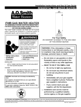
The water heater must be installed according to all local and state codes or in the absence of local
and state codes, the “National Fuel Gas Code”’ ANSI Z223.1(NFPA 54)- current edition.
INSTALLATION OF RESIDENTIAL GAS WATER HEATER
See Labels and
Installation Instructions
and Use & Care Guide
for clearances.
* NOTE: If on a well system the expansion tank should be set to the maximum pressure of the pump tank.
** White-Rodgers® gas control valve/thermostat shown in this figure. The valve may vary according to model and year.
*Massachusett: Install
a vacuum relief in cold
water line per section
19 MGL 142.
Do not cap or plug.
Union
Manual Gas
Shut-off Valve
Untempered
Hot Water
Tempered Water
To Fixtures
Cold
Water
Inlet
Hot
Water
Outlet
Mixing Valve
(Set to 120°F)
Follow the Mixing
Valve Manufacturer’s
Instructions
BASIC INSTALLATION & OPERATION
Figure 1

9
This portion of this handbook applies to the Operations and Servicing of Residential Gas, Tank Type, Water
Heaters, which are vented atmospherically and use a thermocouple as their electrical source.
Control: There are two gas control valve/thermostat confi gurations available. Both valves have similar control
elements such as the Gas Control Knob & Water Temperature Dial. Both valves have high water temperature limit
safety. Please note the location of the control elements on the following fi gures.
Hot Water
Outlet
Cold Water
Inlet
Draft Hood
Flue Baffle
Anode Rod
Foam Fill
Hole
Draft Hood
Temperature-Pressure
Relief Valve
Dip Tube
Flue Baffle
Gas Control Valve
/Thermostat
Drain Valve
Anode
Rod
Flue
Tube
Jacket
Temperature Probe
/High Limit Probe
Gas Control Knob
On|Pilot|Off
Water
Temperature
Dial
Water
Temperature
Dial
Gas Control Knob
Off|Pilot|On
Setting Indicator
(Index Bar)
Thermal Switch
Wire Leads
with Connectors
(some models)*
Reset
Button
Robertshaw®
Gas Control Valve/
Thermostat
White-Rodgers®
Gas Control Valve/
Thermostat
Gas Supply- Inlet
Gas
Supply
- Inlet
*NOTE: Some models do not have thermal switch wire leads as shown in this figure.
** Manifold Gas Pressure Taps are located on the underside of the gas control valve/thermostat.
**Manifold Gas
Pressure Tap
**Manifold Gas
Pressure Tap
BASIC INSTALLATION & OPERATION
Figure 2

10
Burner/Manifold Door Assembly: The burner/manifold assembly consists of several components such as:
main burner, burner orifi ce, manifold tube, pilot burner, pilot orifi ce, pilot tube, igniter, and thermocouple. See the
fi gure below for the complete list of components.
The pilot burner remains on once it is manually lit. When incoming cold water activates the thermostat, gas fl ows
to the main burner. The pilot fl ame ignites this gas. The main fl ame burns until the tank reaches set temperature
then the thermostat interrupts this main gas fl ow.
Burner Orifice*
Main Burner
Pilot (Burner)
Thermocouple
Burner Screws
Manifold Door
Door Gasket
Manifold Tube
Pilot Tube
Igniter Wire
View Port
TCO (Thermal Cut
Off) Switch
Igniter Wire
TCO (Thermal Cut
Off) Sensor
Front View
TCO Reset
Button
Pilot (Burner)
Thermocouple
Pilot Orifice*
Ferrule
Pilot Nut
Pilot Tube
Pilot Bracket
*DO NOT operate the water heater without the pilot and burner orifices installed.
NOTE: The base of the
Thermocouple must be
flush with the base of
the pilot bracket.
Pilot Assembly View
Piezo Igniter Tip
BASIC INSTALLATION & OPERATION
Gas Control Knob
Reset
Button
Pilot
Flame
Safety Valve
Safety Valve
RobertShaw Gas Control Valve/Thermostat Shown.
Figure 3
Figure 4
Normal Operation
Pilot: The pilot fl ame heats the end of a thermocouple.
As the thermocouple gets hotter, it generates a small
(cannot be detected without an electrical meter)
electrical current to the bottom of the gas control valve/
thermostat. This current powers the electromagnet
and holds open the main gas interrupter as long as the
pilot fl ame is heating the thermocouple. The normal
voltage for a properly working thermocouple is between
20 and 30 mv. DANGER! If the pilot is extinguished,
it can take up to 180 seconds for the thermocouple to
cool suffi ciently to close the safety valve.

11
Energy Cut Off (ECO): A metal tube (Temperature
Probe) mounted onto the back of the gas control
valve/thermostat is immersed inside the tank water.
The probe acts as a temperature high limit. If water
gets excessively hot, an Energy Cut Off (ECO) switch
within the probe opens, interrupting the small electrical
current to the gas valve, and gas fl ow through the
control is interrupted. NOTE: If this safety sensor opens,
the entire control must be replaced. The ECO is NOT
resettable.
Thermal Cut Off Switch (TCO): The water heater
is also equipped with a resettable thermal switch,
designed to shut off the gas supply in the event the
water heater has been exposed to high combustion
chamber temperatures caused by fl ammable vapors
(e.g. spilled gasoline), poor combustion caused by a
blocked vent or insuffi cient combustion air.
Gas: When you prepare to light the pilot, you are
instructed to turn the gas control knob to the pilot
position and depress the gas control knob (Reset button
on Robertshaw Gas Valves). When depressed gas will
fl ow to the pilot burner only. You then have to (manually)
ignite this pilot gas using the piezo igniter button. When the pilot is lit, the fl ame must heat the thermocouple until
it generates suffi cient voltage to the gas valve to allow you to release the knob while gas continues to fl ow to
the pilot. When the gas control knob is turned to the “ON” position, gas is also available to the main burner if the
thermostat calls for heat.
Water Flow: When a hot water faucet is opened, water pressure from the well tank or street main forces cold
water into the water heater through the dip tube. This pushes hot water out of the tank.
BASIC INSTALLATION & OPERATION
Figure 5
Reset Button
TCO Reset
Button
NOTE: RobertShaw® Gas Control
Valve/Thermostat shown.
Gas Control Valve/Thermostat - Side View
Gas Control Knob
Gas Inlet
Temperature
Probe
Protective
Plastic Sleeve
Thermocouple
Temperature
Sensor
ECO
TCO (Thermal
Cut O) Sensor
TCO (Thermal
Cut O) Switch

12
Thermostat Operation: Standard residential water heaters use mechanical thermostats. With a mechanical
thermostat, a dial setting of 120° F may shut the burner down at a tank temperature between 110° and 130° F.
The heater will consistently shut off at this same temperature. For this same reason, water temperature may drop
15° F - 25° F, around the temperature probe, before the main burner is activated. Keep in mind that hot water in
the upper part of the tank will probably be very near the “shut off” temperature of the control while incoming cold
water drops the water temperature around the thermostat probe. Also short, repeating heating cycles caused by
small hot water uses can cause temperatures at the point of use to exceed the thermostat setting by up to 30° F.
Water Temperature Time to Produce 2nd & 3rd
Degree Burns on Adult Skin
160°F (71°C)
About 1/2 second
150°F (66°C) About 1-1/2 seconds
140°F (60°C) Less than 5 seconds
130°F (54°C) About 30 seconds
120°F (49°C) More than 5 minutes
80°F (27°C) - - - - - - - - - - - - - - - -
Gas Control Knob
On|Pilot|Off
Gas Control Knob
Off|Pilot|On
Robertshaw®
Gas Control Valve/
Thermostat
White-Rodgers®
Gas Control Valve/
Thermostat
120°F Mark
Water
Temperature
Dial
130°F
140°F
150°F
130°F
140°F
150°F
Reset Button
Note: Temperature marks noted above are approximate and may vary due to various factors.
BASIC INSTALLATION & OPERATION
Figure 6

13
BASIC INSTALLATION & OPERATION
Table 1:
BTUH Input
Minimum Square
Feet with
8’ Ceiling
Typical Room
with 8’ Ceiling
30,000 188 9 x 21
45,000 281 14 x 20
60,000 375 15 x 25
75,000 469 15 x 31
90,000 563 20 x 28
105,000 657 20 x 33
120,000 750 25 x 30
135,000 844 28 x 30
IMPORTANT:
• The area must be open and be able to provide
the proper air requirements to the water heater.
Areas that are being used for storage or contain
large objects may not be suitable for water heater
installation.
• Water heaters installed in open spaces in buildings
with unusually tight construction may still require
outdoor air to function properly. In this situation,
outside air openings should be sized the same as
for a confined space.
• Modern home construction usually requires
supplying outside air into the water heater area.
• Room exhaust fans may effect air requirements.
Confi ned Space: For the correct and proper operation
of this water heater, ample air must be supplied for
the combustion, ventilation, and dilution of fl ue gases.
Small enclosures and confi ned areas must have two
permanent openings so that suffi cient fresh air can be
drawn from outside of the enclosure. One opening shall
be within 12 inches of the top and one within 12 inches
of the bottom of the enclosure.
The size of each opening (free area) is determined by
the total BTUH input of all gas utilization equipment
(i.e., water heaters, furnaces, clothes dryers, etc.) and
the method by which the air is provided. The BTUH
input can be found on the water heater rating plate.
Additional air can be provided by two methods:
1. All air from inside the building.
2. All air from outdoors.
12” MAXIMUM
PERMANENT
OPENINGS TO
T
HE OUTSIDE OR
ADDITIONAL
ROOMS WITHIN
THE BUILDING
CLOSET
OR
OTHER
CONFINED
SPACE
12” MAXIMUM
Combustion Air Requirements:
WARNING
Carbon Monoxide Warning
Water heater must be vented to outdoors.
Vent must be installed by a qualified technician using
the local and state codes or, in the absence of local
and state codes, the National Fuel Gas Code,
ANSI Z223.1 (NFPA 54) - current edition, and/or the
installation instructions.
Examples of a qualified technican include: gas
technicians, authorized gas company personel, and
authorized service persons.
Failure to so do can result in death or carbon monoxide
poisoning.
IMPORTANT: Air for combustion and ventilation must
not come from a fl ammable or corrosive atmosphere.
Any failure due to fl ammable or corrosive elements in
the atmosphere is excluded from warranty coverage.
The following types of installation (not limited to the
following) will require outdoor air for combustion due to
chemical exposure and may reduce but not eliminate
the presence of corrosive chemicals in the air:
• beauty shops
• photo processing labs
• buildings with indoor pools
• water heaters installed in laundry, hobby, or craft
rooms
• water heaters installed near chemical storage areas
• water softeners
Combustion air must be free of acid-forming chemicals
such as sulfur, fl uorine, and chlorine. These elements
are found in aerosol sprays, detergents, bleaches,
cleaning solvents, air fresheners, paint, and varnish
removers, refrigerants, and many other commercial
and household products. When burned, vapors from
these products form highly corrosive acid compounds.
These products should not be stored or used near the
water heater, air inlet, or air intake path.
Combustion and ventilation air requirements are
determined by the location of the water heater.
The water heater may be located in either an open
(unconfi ned) area or in a confi ned area or small
enclosure such as a closet or small room. Confi ned
spaces are areas with less than 50 cubic feet for
each 1,000 BTUH of the total input for all gas-using
appliances.
Unconfi ned Space: A water heater in an unconfi ned
space uses indoor air for combustion and requires at
least 50 cubic feet for each 1,000 BTUH of the total
input for all gas appliances. The table below shows a
few examples of the minimum square footage (area)
required for various BTUH inputs.
Figure 7

14
BASIC INSTALLATION & OPERATION
All Air from Inside the Building: When additional air
is to be provided to the confi ned area from additional
room(s) within the building, the total volume of the
room(s) must be of suffi cient size to properly provide
the necessary amount of fresh air to the water heater
and other gas utilization equipment in the area. Each
of the two openings shall have a minimum free area of
1 square inch per 1,000 BTUH of the total input rating
of all gas utilization equipment in the confi ned area, but
not less than 100 square inches for each opening.
Figure 8
All Air from Outdoors: Outdoor fresh air can be
provided to a confined area either directly or by the use
of vertical and horizontal ducts. The fresh air can be
taken from the outdoors or from crawl or attic spaces
that freely communicate with the outdoors. Attic or
crawl spaces cannot be closed and must be properly
ventilated to the outside.
Ductwork must be of the same cross-sectional area
as the free area of the opening to which they connect.
The minimum dimension of rectangular air ducts
cannot be less than three inches.
The size of each of the two openings is determined by
the method in which the air is to be provided. Refer to
the table below to calculate the minimum free area for
each opening.
Louvers and Grilles: In calculating free area for
ventilation and combustion air supply openings,
consideration must be given to the blocking effect of
protection louvers, grilles, and screens. These devices
can reduce airflow, which in turn may require larger
openings to achieve the required minimum free area.
Screens must not be smaller than 1/4” mesh. If the
free area through a particular design of louver or grille
is known, it should be used in calculating the specified
free area of the opening. If the design and free area
are not known, it can be assumed that most wood
louvers will allow 20 - 25% of free area while metal
louvers and grilles will allow 60 - 75% of free area.
Louvers and grilles must be locked open or
interconnected with the equipment so that they are
opened automatically during equipment operation.
Keep louvers and grilles clean and free of debris or
other obstructions.
Minimum Free Area of Permanent Openings for
Ventilation and Combustion Air Supply - All Air from
Outdoors Only.
Based on total BTUH input rating for all utilizing
equipment within the confi ned space.
Opening Source
Minimum Free Area
Per Opening (sq. in.)
Reference
Drawing
*Direct to outdoors 1 sq. in, per 4000 BTUH Figure 9
Vertical Ducts 1 sq. in, per 4000 BTUH Figure 10
Horizontal Ducts 1 sq. in, per 2000 BTUH Figure 11
Single Opening 1 sq. in, per 3000 BTUH Figure 12
Example: A water heater with an input rating of 50,000 BTUH
using horizontal ducts would require each opening to have a
minimum free area of 25 square inches.
Minimum free area = 50,000 BTUH x 1 sq. in. / 2000 BTUH = 25
sq. in.
*
These openings connect directly with the outdoors
through a ventilated attic, a ventilated crawl space, or
through an outside wall.
Consult the local codes of your area for specific
ventilation and combustion air requirements
ABLE VENT
TO OUTDOORS
INSTALL ABOVE
INSULATION
CONFINED
SPACE
ALTERNATE
AIR INLET
OUTLET
AIR TO
ATTIC 1 SQ.
INCH PER
4000 BTUH
INLET AIR FROM
THE CRAWL SPACE
OPEN
FOUNDATION
VENT
1 SQ. INCH PER
4000 BTUH
100 SQ. INCH MINIMUM (EACH)
ALL AIR FROM OUTDOORS: INLET AIR FROM VENTILATED
CRAWL SPACE/OUTLET AIR TO VENTILATED ATTIC
GABLE VENT
TO OUTDOORS
INSTALL ABOVE
INSULATION
CONFINED
SPACE
OUTLET AIR TO
ATTIC 1 SQ. INCH
PER 4000 BTUH -
100 SQ. INCH MIN.
(EACH)
INLET AIR DUCT
1 SQ. INCH PER
4000 BTUH - 100
SQ. INCH MIN.
(EACH)
12” MAXIMUM
ALL AIR FROM OUTDOORS THROUGH VENTILATED ATTIC
CONFINED
SPACE
PERMANENT
OPENINGS
1 SQUARE
INCH/1000
BTUH
(MINIMUM
100 SQ. IN.
FOR EACH
OPENING)
Figure 9
Figure 10

15
BASIC INSTALLATION & OPERATION
Vent Connectors:
1. Type B, Double wall, U.L. Listed Vent Pipe.
2. Single wall Vent Pipe.
Maintain the manufacturer’s specifi ed minimum
clearance from combustible materials when using type
B double wall vent pipe.
Vent connectors made of type B, double wall vent
pipe material may pass through walls or partitions
constructed of combustible material if the minimum
listed clearance is maintained.
Maintain a one inch minimum clearance from all
combustible materials when using single wall vent pipe.
IMPORTANT: Single wall vent pipe cannot be used
for water heaters located in attics and may not pass
through attic spaces, crawl spaces or any confi ned
or inaccessible location. A single wall metal vent
connector cannot pass through any interior wall.
When installing a vent connector, please note the
following
• Install the vent connector avoiding unnecessary
bends, which create resistance to the flow of vent
gases.
• Install without dips or sags with an upward slope of
at least 1/4-inch per foot.
• Joints must be fastened by sheet metal screws
or other approved means. It must be supported
to maintain clearances and prevent separation of
joints and damage.
• The length of the vent connector cannot exceed
75% of the vertical vent height.
• The vent connector must be accessible for clean-
ing, inspection, and replacement.
• Vent connectors cannot pass through any ceiling,
floor, firewall, or fire partition.
• It is recommended (but not mandatory) that
a minimum 12 inches of vertical vent pipe be
installed on the draft hood prior to any elbow in the
vent system.
IMPORTANT: Existing vent systems must be inspected
for obstructions, corrosion, and proper installation.
Chimney Connection: IMPORTANT: Before
connecting a gas vent to a chimney, make sure the
chimney passageway is clear and free of obstructions.
The chimney must be cleaned if previously used for
venting solid fuel appliances or fireplaces. Also consult
local and state codes for proper chimney sizing and
application or, in the absence of local and state codes,
the “National Fuel Gas Code”, ANSI Z223.1(NFPA
54)-current edition.
• The connector must be installed above the
extreme bottom of the chimney to prevent
potentially blocking the flue gases.
Figure 11
Figure 12
Vent Pipe System: This water heater must be
properly vented for the removal of exhaust gases to
the outside atmosphere. Correct installation of the vent
pipe system is mandatory for the proper and effi cient
operation of this water heater and is an important
factor in the life of the unit.
The vent pipe must be installed according to all
local and state codes or, in the absence of local and
state codes, the “National Fuel Gas Code”, ANSI
Z223.1(NFPA 54)-current edition. The vent pipe
installation must not be obstructed so as to prevent the
removal of exhaust gases to the outside atmosphere.
U.L. recognized fuel gas and carbon monoxide
(CO) detectors are recommended in all applications
and should be installed using the manufacturer’s
instructions and local codes, rules, or regulations.
Vent Pipe Size: It is important that you follow the
guidelines in these instructions for sizing a vent pipe
system. If a transition to a larger vent size is required,
the vent transition connection must be made at the
draft hood outlet. DO NOT reduce the vent size to less
than the draft hood outlet diameter.
1 SQ. INCH PER
2000 BTUH
100 SQ. INCH
MINIMUM (EACH)
CONFINED
SPACE
1 SQ. INCH PER
2000 BTUH 100 SQ. INCH
MINIMUM (EACH)
INLET
OUTLET
OUTDOOR
AIR DUCTS
ALL AIR FROM OUTDOORS USING HORIZONTAL DUCTS
ALTERNATIVE
OPENING
LOCATION
1 SQ. INCH
PER 3000 BTUH
100 SQ. INCH
MINIMUM (EACH)
CONFINED
SPACE
ALL AIR FROM OUTDOORS - USING A SINGLE PERMANENT OPENING

16
• The connector must be firmly attached and sealed
to prevent it from falling out.
• To aid in removing the connector, a thimble or slip
joint may be used.
• The connector must not extend beyond the inner
edge of the chimney as it may restrict the space
between it and the opposite wall of the chimney
LISTED LINED
CHIMNEY
2 FT. MINIMUM ABOVE ANY OBJECT
WITHIN 10FT. HORIZONTALLY
DO NOT EXTEND
VENT BEYOND EDGE
OF CHIMNEY
VENT
CONNECTOR
3 FT. MINIMUM
MAINTAIN
CLEARANCE*
SEAL
SLOPE
UP 1/4 IN.
PER FT.
MINIMUM
CHIMNEY TERMINATION VENT SYSTEM
SUPPORT
STRAP
Figure 13
Do not reduce the vent to less than the draft hood
outlet diameter. Do not terminate the vent connector in
a chimney that has not been certified for this purpose.
Some local codes may prohibit the termination of vent
connectors in a masonry chimney.
Vertical Exhaust Gas Vent: Vertical exhaust gas
vents must be installed with U.L. listed type B vent pipe
according to the vent manufacturer’s instructions and the
terms of its listing.
It must be connected to the water heater’s draft hood by a
listed vent connector or by directly originating at the draft
hood opening.
Vertical gas vents must terminate with a listed cap or
other roof assembly and be installed according to their
manufacturer’s instructions.
Gas vents must be supported to prevent damage, joint
separation, and maintain clearances to combustible
materials.
IMPORTANT: This gas vent must be terminated in a
vertical position to facilitate the removal of the burnt
gases.
An unused chimney fl ue or masonry enclosure may be
used as a passageway for the installation of a gas vent.
NOTE: The chimney fl ue or masonry enclosure size may
be too large to allow proper venting.
Common (combined) venting is allowable with vertical
type B vent systems and lined masonry chimneys as long
as proper draft for the water heater is established under
all conditions of operation. CAUTION: DO NOT common
vent this water heater with any power vented appliance.
The following fi gures are examples of vent pipe system
installations and may or may not be typical for your
specifi c application. Consult the “National Fuel Gas
Code”, NFPA 54, ANSI Z223.1-current edition and the
guidelines set forth by prevailing local codes.
VERTICAL GAS VENT SYSTEM WITH
TYPE B DOUBLE WALL VENT PIPE.
LISTED VENT CAP
TYPE B DOUBLE
WALL VENT PIPE
**MAINTAIN
SPECIFIED
CLEARANCE
VENT
CONNECTOR
SLOPE UP
1/4 IN. PER FT.
MINIMUM
*MAINTAIN
CLEARANCE
SUPPORT
STRAP
LISTED GAS VENT
LOWEST DISCHARGE OPENING
H (MINIMUM) - MINIMUM HEIGHT FROM
ROOF TO LOWEST DISCHARGE OPENING
12
x
ROOF PITCH IS x/12
Figure 14
Consult the table found in the “National Fuel Gas
Code”, NFPA 54, ANSI Z223.1-current edition to
determine the minimum height from roof to lowest
discharge opening.
VENTING THROUGH A CHIMNEY WITH
TYPE B DOUBLE WALL VENT PIPE.
LISTED VENT CAP
VENT CONNECTOR
UNUSED CHIMNEY
FLUE OR MASONRY
ENCLOSURE
SEAL
*MAINTAIN
CLEARANCE
VENT
CONNECTOR
SLOPE UP
1/4 IN. PER FT.
MINIMUM
**MAINTAIN
SPECIFIED
CLEARANCE
SUPPORT
STRAP
MAINTAIN MANUFACTURER’S
SPECIFIED MINIMUM CLEARANCE
Figure 15
*
Maintain vent pipe clearance requirements to local, state
and/or the “National Fuel Gas Code”, ANSI Z223.1(NFPA
54)-current edition.
**
NFPA 211, Standard for Chimneys, Fireplaces, Vents, and
Solid Fuel-Burning Appliances states that these chimneys are
intended to be installed in accordance with the installation
instructions provided with each chimney support assembly.
Minimum air space clearance to combustible materials should be
maintained as marked on the chimney sections.
BASIC INSTALLATION & OPERATION

17
DRAINING AND FILLING THE WATER HEATER
D raining the Water Heater
The water heater should be drained if being shut down
during freezing temperatures. Also, periodic draining
and cleaning of sediment from the tank may be
necessary.
1. Turn off the gas to the water heater at the manual
gas shut-off valve.
2. Open a nearby hot water faucet until the water is
no longer hot.
3. Close the cold water inlet valve.
4. Connect a hose to the drain valve and terminate
it to an adequate drain or external to the building.
(Make sure all connections are tight and that the
water flow is directed away from people.)
5. Open the water heater drain valve and allow all the
water to drain from the tank. Flush the tank with
water as needed to remove sediment.
6. Close the drain valve, refill the tank, and restart the
heater as directed by the lighting instructions on
the front of the water heater.
If the water heater is going to be shut down for an
extended period, the drain valve should be left open.
IMPORTANT: Condensation may occur when the cold
tank is first heated and should not be confused with a
tank leak.
F illing the Water Heater
Never use this water heater unless it is completely full
of water. To prevent damage, the tank must be fi lled
with water. Water must fl ow from the hot water faucet
before lighting the water heater. NOTE: The hot water
faucet used should be the one furthest from the water
heater.
To fi ll the water heater with water:
1. Close the water heater drain valve.
2. Open the cold water supply shut off valve to the
water heater.
3. To ensure complete fi lling of the tank, allow air to
exit by opening the furthest hot water faucet. Allow
water to run until a constant fl ow is obtained. This
will let air out of the water heater and the piping.
4. Check all new water piping for leaks. Repair as
needed.

18
CHECKING THE GAS SUPPLY PRESSURE
Checking the Gas Supply Pressure
Gas pressure checks are done with flowing gas using
a gas pressure gauge capable of reading pressure in
inches of water column.
• Supply gas pressure checks are measured before
the gas control valve/thermostat and as close to
the water heater as possible.
• Manifold (main burner) gas pressure is measured
at the pressure tap on the bottom of the gas
control valve/thermostat. Use an Allen wrench to
remove the plug then attach the gas gauge.
NOTE: Desired gas pressures will be noted on the
gas valve label located on the gas control valve/
thermostat.
GAS
PRESSURE
GAUGE
CONNECTED AT
PRESSURE TAP
MANIFOLD GAS PRESSURE TEST
WHITE RODGERS GAS CONTROL
VALVE/THERMOSTAT SHOWN
GAS PRESSURE LABEL
Figure 16
IF . . . . . . THEN
supply gas pressure is under desired pressure
requirement
• increase supply gas pressure regulator setting
and,
• increase supply gas piping size.
supply gas pressure is over desired pressure • add gas pressure regulator.
• reduce setting on existing regulator.
manifold gas pressure is more than +/- .3 inch
W.C. from values indicated on gas valve
ensure there is adequate supply gas pressure•
e• nsure the main burner orifi ce is the correct size
for the water heater model being tested.
if the above tests have been performed and the •
results were correct replace the gas control valve.
Combustion Air Test
The Installation Instructions and Use & Care Guide
gives guidelines under “Air Requirements” and
“Unconfined “ or “Confined Space” sections. If you
want to test for a lack of air:
1. Turn on every appliance and fan that exhausts
air from the utility room and/or house. Make
sure all windows and doors are closed, as well
as chimney dampers.
2. Open a hot water faucet so that the main
burner will ignite
3. Remove the outer door of the water heater –
not the inner door
4. Monitor the flame characteristics for several
minutes
If the flame begins to “yellow” open a door or window,
to the outdoors, to see if additional air corrects this
back to blue. If it does, the room needs more air
supply.
CHECKING FOR SUFFICIENT COMBUSTION AIR OR VENTING ISSUES
REVERSE FLOW
OF VENT PRODUCTS
EXHAUST FAN
VENT
Figure 17

19
CHECKING FOR SUFFICIENT COMBUSTION AIR OR VENTING ISSUES
Flue Products Vented
to Ouside of Building
Draft Hood
Dilution Air
Air is drawn in for combustion.
Keep area clean and free from
combustibles and flammable vapors.
Dilution Air
(Relief Opening)
Dilution Air
Match
Outer Door
Draft Test
After successfully lighting the water heater, allow the
unit to operate for 15 minutes and check the draft
hood relief opening for proper draft. Make sure all
other appliances in the area are operating and all
doors/windows are closed when performing the draft
test. Pass a match flame or smoke around the relief
opening of the draft hood. A steady flame or smoke
drawn into the opening indicates proper draft.
If the flame flutters or is blown out, combustion
products are escaping from the relief opening. If this
occurs, do not operate the water heater until proper
adjustments or repairs are made to the vent pipe
system and/or air supply requirements.
External Inspection & Cleaning of
the Base-Ring Filter
1. At least annually check the base-ring filter for any
dust or debris that may have accumulated on the
filter screen. NOTE: If the water heater is located
in an area that is subjected to lint and dirt, it may
be necessary to check the base-ring filter more
frequently.
2. Follow the Lighting Instructions to turn off the water
heater and allow it to cool for 10 minutes before
attempting to clean the base-ring filter.
3. Use a vacuum cleaner with a hose attachment
to remove any dust or debris that may have
accumulated on the filter. NOTE: If unable to
inspect or clean the base-ring filter, follow the
“Cleaning the Combustion Chamber and Flame-
arrestor” instructions below.
4. After the base-ring filter has been cleaned, follow
the Lighting Instructions to return the water heater to
service.
Cleaning the Combustion Chamber
and Flame-arrestor
1. Follow procedure outlined in “Removing the
Manifold/Burner Assembly” (See page 22).
2. Use a vacuum cleaner/shop vac to remove all
loose debris in the combustion chamber. Use
compressed air to clear any dust or debris that
may have accumulated in the flame-arrestor.
DOOR GASKET
FLAME ARRESTOR
COMBUSTION CHAMBER
BASE-RING
FILTER
Figure 19
3. Reassemble following the procedure under
“Replacing the Manifold/Burner Assembly” (See
page 21).
Figure 18

20
TESTING THE THERMOCOUPLE AND GAS CONTROL VALVE/THERMOSTAT
Thermocouple Output Test
The following test will check the DC voltage generated
by the thermocouple when the pilot light is lit.
1. Disconnect the thermocouple from the gas control
valve/thermostat as shown in the adjacent figure.
2. Using a multimeter with alligator clips leads,
attach the red lead to the body (copper part) of the
thermocouple. Attach the black lead to the end
(silver part) of the thermocouple. Reference the
adjacent image for placement of the leads.
3. Follow the lighting instructions on the front of the
water heater to light the pilot and watch the voltage
readings on the multimeter. NOTE: You will have
to hold the button down to keep the pilot lit for the
duration of the test. After 45 seconds the meter
should read 20-30 millivolts DC or more.
IF . . . . . . THEN
the multimeter voltage reads
at least 20-30 millivolts DC
• check the positioning of the thermocouple tip to the pilot flame. If
necessary position the thermocouple to ensure the flame contacts the
thermocouple’s tip. Re-test the thermocouple, and if it fails replace the
thermocouple. (See p. 22)
the multimeter voltage reads
more than 20-30 millivolts DC
• the thermocouple is working properly. Proceed to the gas control valve/
thermostat test.
Gas Control Valve/Thermostat Test
(Thermal Switch Models)
The following test will check the gas control valve/
thermostat’s ECO & TCO (Energy Cut Off & Thermal Cut
Off). NOTE: This test applies to gas valves with wire leads
that attach to the thermal switch on the manifold door.
Remove both wire leads from the TCO (thermal cut 1.
off switch) and jumper the two leads to complete
the circuit. Once the test is complete, remove the
jumper and reconnect the wire leads.
Follow the lighting instructions on the front of the 2.
water heater to light the pilot.
Release the knob and check to see if the pilot 3.
remains lit.
TCO
WIRE LEADS
(JUMPERED)
TCO
SWITCH
TCO
WIRE LEADS
GAS CONTROL
KNOB
IF . . . . . . THEN
the pilot lights and remains lit • the TCO (thermal switch sensor) has tripped OR the TCO is not
working (OPEN). Reattach the wire leads and press the TCO reset
button. Relight the water heater. If the pilot will not remain lit, replace
the TCO. If the pilot does remain lit, the TCO was tripped-possibly
due to a lack of combustion air (see pp 13-16 & 18-19) OR because
of a Flammable Vapor event. Check around the water heater for any
source of fl ammable vapors (i.e. gasoline, paint thinner, etc.).
the pilot will not light or remain
lit with the wire leads jumpered
• replace the gas control valve/thermostat.
(See p. 24)
Figure 20
Figure 21
IMPORTANT: Before performing any test, check the area around the water heater for any source of a Flammable
Vapor (i.e gasoline, paint thinners, etc.) If any sources are found do not proceed until they are removed.
/