Agilent Technologies 85032B User manual
- Category
- Networking
- Type
- User manual
This manual is also suitable for

User’s and Service Guide
Agilent Technologies 85032B/E
50
Ω
Type-N Calibration Kits
Agilent Part Number: 85032-90020
Printed in USA
Print Date: July 2002
Supersedes: June 2000
© Copyright 1993, 2000, 2002 Agilent Technologies, Inc. All rights reserved.

ii 85032B/E
Documentation Warranty
THE MATERIAL CONTAINED IN THIS DOCUMENT IS PROVIDED "AS IS," AND IS
SUBJECT TO BEING CHANGED, WITHOUT NOTICE, IN FUTURE EDITIONS.
FURTHER, TO THE MAXIMUM EXTENT PERMITTED BY APPLICABLE LAW,
AGILENT DISCLAIMS ALL WARRANTIES, EITHER EXPRESS OR IMPLIED WITH
REGARD TO THIS MANUAL AND ANY INFORMATION CONTAINED HEREIN,
INCLUDING BUT NOT LIMITED TO THE IMPLIED WARRANTIES OF
MERCHANTABILITY AND FITNESS FOR A PARTICULAR PURPOSE. AGILENT
SHALL NOT BE LIABLE FOR ERRORS OR FOR INCIDENTAL OR CONSEQUENTIAL
DAMAGES IN CONNECTION WITH THE FURNISHING, USE, OR PERFORMANCE
OF THIS DOCUMENT OR ANY INFORMATION CONTAINED HEREIN. SHOULD
AGILENT AND THE USER HAVE A SEPARATE WRITTEN AGREEMENT WITH
WARRANTY TERMS COVERING THE MATERIAL IN THIS DOCUMENT THAT
CONFLICT WITH THESE TERMS, THE WARRANTY TERMS IN THE SEPARATE
AGREEMENT WILL CONTROL.
Assistance
Product maintenance agreements and other customer assistance agreements are available
for Agilent products.
For any assistance, contact Agilent Technologies. Refer to page 5-3.

Contents
85032B/E iii
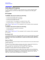
1. General Information
Calibration Kit Overview. . . . . . . . . . . . . . . . . . . . . . . . . . . . . . . . . . . . . . . . . . . . . . . . . . . . . .1-2
Kit Contents . . . . . . . . . . . . . . . . . . . . . . . . . . . . . . . . . . . . . . . . . . . . . . . . . . . . . . . . . . . . . .1-2
Broadband Loads. . . . . . . . . . . . . . . . . . . . . . . . . . . . . . . . . . . . . . . . . . . . . . . . . . . . . . . . .1-2
Opens and Shorts . . . . . . . . . . . . . . . . . . . . . . . . . . . . . . . . . . . . . . . . . . . . . . . . . . . . . . . .1-2
Adapters. . . . . . . . . . . . . . . . . . . . . . . . . . . . . . . . . . . . . . . . . . . . . . . . . . . . . . . . . . . . . . . .1-3
Calibration Definitions. . . . . . . . . . . . . . . . . . . . . . . . . . . . . . . . . . . . . . . . . . . . . . . . . . . . . .1-3
Installation of the Calibration Definitions. . . . . . . . . . . . . . . . . . . . . . . . . . . . . . . . . . . . .1-3
Options. . . . . . . . . . . . . . . . . . . . . . . . . . . . . . . . . . . . . . . . . . . . . . . . . . . . . . . . . . . . . . . . .1-3
Equipment Required but Not Supplied . . . . . . . . . . . . . . . . . . . . . . . . . . . . . . . . . . . . . . .1-3
Incoming Inspection. . . . . . . . . . . . . . . . . . . . . . . . . . . . . . . . . . . . . . . . . . . . . . . . . . . . . . . . . .1-4
Recording the Device Serial Numbers . . . . . . . . . . . . . . . . . . . . . . . . . . . . . . . . . . . . . . . . . . .1-5
Clarifying the Sex of a Connector . . . . . . . . . . . . . . . . . . . . . . . . . . . . . . . . . . . . . . . . . . . . . . .1-6
Preventive Maintenance . . . . . . . . . . . . . . . . . . . . . . . . . . . . . . . . . . . . . . . . . . . . . . . . . . . . . .1-6
2. Specifications
Environmental Requirements . . . . . . . . . . . . . . . . . . . . . . . . . . . . . . . . . . . . . . . . . . . . . . . . .2-2
Temperature—What to Watch Out For . . . . . . . . . . . . . . . . . . . . . . . . . . . . . . . . . . . . . . . . .2-2
Mechanical Characteristics . . . . . . . . . . . . . . . . . . . . . . . . . . . . . . . . . . . . . . . . . . . . . . . . . . . .2-3
Pin Depth. . . . . . . . . . . . . . . . . . . . . . . . . . . . . . . . . . . . . . . . . . . . . . . . . . . . . . . . . . . . . . . . .2-3
Electrical Specifications. . . . . . . . . . . . . . . . . . . . . . . . . . . . . . . . . . . . . . . . . . . . . . . . . . . . . . .2-5
Certification. . . . . . . . . . . . . . . . . . . . . . . . . . . . . . . . . . . . . . . . . . . . . . . . . . . . . . . . . . . . . . .2-5
Supplemental Electrical Characteristics. . . . . . . . . . . . . . . . . . . . . . . . . . . . . . . . . . . . . . . .2-5
3. Use, Maintenance, and Care of the Devices
Electrostatic Discharge . . . . . . . . . . . . . . . . . . . . . . . . . . . . . . . . . . . . . . . . . . . . . . . . . . . . . . .3-2
Visual Inspection . . . . . . . . . . . . . . . . . . . . . . . . . . . . . . . . . . . . . . . . . . . . . . . . . . . . . . . . . . . .3-3
Look for Obvious Defects and Damage First. . . . . . . . . . . . . . . . . . . . . . . . . . . . . . . . . . . . .3-3
What Causes Connector Wear?. . . . . . . . . . . . . . . . . . . . . . . . . . . . . . . . . . . . . . . . . . . . . .3-3
Inspect the Mating Plane Surfaces . . . . . . . . . . . . . . . . . . . . . . . . . . . . . . . . . . . . . . . . . . . .3-3
Inspect Female Connectors. . . . . . . . . . . . . . . . . . . . . . . . . . . . . . . . . . . . . . . . . . . . . . . . . . .3-4
Cleaning Connectors . . . . . . . . . . . . . . . . . . . . . . . . . . . . . . . . . . . . . . . . . . . . . . . . . . . . . . . . .3-4
Gaging Connectors . . . . . . . . . . . . . . . . . . . . . . . . . . . . . . . . . . . . . . . . . . . . . . . . . . . . . . . . . . .3-6
Connector Gage Accuracy. . . . . . . . . . . . . . . . . . . . . . . . . . . . . . . . . . . . . . . . . . . . . . . . . . . .3-6
When to Gage Connectors. . . . . . . . . . . . . . . . . . . . . . . . . . . . . . . . . . . . . . . . . . . . . . . . . . . .3-7
Reading the Connector Gage . . . . . . . . . . . . . . . . . . . . . . . . . . . . . . . . . . . . . . . . . . . . . . . . .3-7
Gaging Procedures . . . . . . . . . . . . . . . . . . . . . . . . . . . . . . . . . . . . . . . . . . . . . . . . . . . . . . . . .3-8
Gaging Male Type-N Connectors . . . . . . . . . . . . . . . . . . . . . . . . . . . . . . . . . . . . . . . . . . . .3-8
Gaging Female Type-N Connectors . . . . . . . . . . . . . . . . . . . . . . . . . . . . . . . . . . . . . . . . .3-10
Connections. . . . . . . . . . . . . . . . . . . . . . . . . . . . . . . . . . . . . . . . . . . . . . . . . . . . . . . . . . . . . . . .3-12
How to Make a Connection. . . . . . . . . . . . . . . . . . . . . . . . . . . . . . . . . . . . . . . . . . . . . . . . . .3-12
Preliminary Connection . . . . . . . . . . . . . . . . . . . . . . . . . . . . . . . . . . . . . . . . . . . . . . . . . .3-12
Final Connection Using a Torque Wrench. . . . . . . . . . . . . . . . . . . . . . . . . . . . . . . . . . . .3-12
Connecting and Disconnecting the Two-Piece Female Open (85032B) . . . . . . . . . . . . .3-14
How to Separate a Connection. . . . . . . . . . . . . . . . . . . . . . . . . . . . . . . . . . . . . . . . . . . . . . .3-15
Handling and Storage . . . . . . . . . . . . . . . . . . . . . . . . . . . . . . . . . . . . . . . . . . . . . . . . . . . . . . .3-15

iv 85032B/E
Contents
4. Performance Verification
Introduction . . . . . . . . . . . . . . . . . . . . . . . . . . . . . . . . . . . . . . . . . . . . . . . . . . . . . . . . . . . . . . . . 4-2
How Agilent Verifies the Devices in This Kit . . . . . . . . . . . . . . . . . . . . . . . . . . . . . . . . . . . . 4-2
Recertification . . . . . . . . . . . . . . . . . . . . . . . . . . . . . . . . . . . . . . . . . . . . . . . . . . . . . . . . . . . . . . 4-3
Limited Recertification (Option 003). . . . . . . . . . . . . . . . . . . . . . . . . . . . . . . . . . . . . . . . . . . 4-3
How Often to Recertify. . . . . . . . . . . . . . . . . . . . . . . . . . . . . . . . . . . . . . . . . . . . . . . . . . . . . .4-3
Where to Send a Kit for Recertification . . . . . . . . . . . . . . . . . . . . . . . . . . . . . . . . . . . . . . . . 4-3
5. Troubleshooting
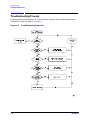
Troubleshooting Process . . . . . . . . . . . . . . . . . . . . . . . . . . . . . . . . . . . . . . . . . . . . . . . . . . . . . . 5-2
Returning a Kit or Device to Agilent . . . . . . . . . . . . . . . . . . . . . . . . . . . . . . . . . . . . . . . . . . . .5-3
6. Replaceable Parts
Introduction . . . . . . . . . . . . . . . . . . . . . . . . . . . . . . . . . . . . . . . . . . . . . . . . . . . . . . . . . . . . . . . . 6-2
A. Standard Definitions
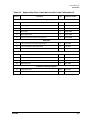
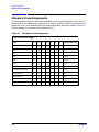
Standard Class Assignments . . . . . . . . . . . . . . . . . . . . . . . . . . . . . . . . . . . . . . . . . . . . . . . . . .A-2
Blank Form. . . . . . . . . . . . . . . . . . . . . . . . . . . . . . . . . . . . . . . . . . . . . . . . . . . . . . . . . . . . . . .A-3
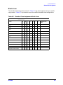
Nominal Standard Definitions . . . . . . . . . . . . . . . . . . . . . . . . . . . . . . . . . . . . . . . . . . . . . . . . .A-4
Setting the System Impedance . . . . . . . . . . . . . . . . . . . . . . . . . . . . . . . . . . . . . . . . . . . . . . .A-4
Blank Form. . . . . . . . . . . . . . . . . . . . . . . . . . . . . . . . . . . . . . . . . . . . . . . . . . . . . . . . . . . . . . .A-6

85032B/E 1-1
1 General Information

1-2 85032B/E
General Information
Calibration Kit Overview
Calibration Kit Overview
The Agilent 85032B and 85032E type-N calibration kits are used to calibrate Agilent
network analyzers up to 6 GHz for measurements of components with 50Ω type-N
connectors.
Kit Contents
The 85032B calibration kit contains the following:
• one male and one female open termination
• one male and one female short termination
• one male and one female 50Ω load
• two type-N-male to 7-mm adapters (included with Option 100)
• two type-N-female to 7-mm adapters (included with Option 100)
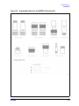
Refer to Table 6-1 and Figure 6-1 for a complete list of kit contents and their associated
part numbers.
The 85032E calibration kit contains the following:
• one male combination open/short termination
• one male 50Ω load
Refer to Table 6-2 and Figure 6-2 for a complete list of kit contents and their associated
part numbers.
Broadband Loads
The broadband loads are instrument-grade, 50Ω terminations that have been optimized for
performance up to 6 GHz. The rugged internal structure provides for highly repeatable
connections. A distributed resistive element on sapphire provides excellent stability and
return loss.
Opens and Shorts
The opens and shorts are built from parts that are machined to the current state-of the-art
precision machining.
The short’s inner conductors have a one-piece construction, common with the shorting
plane. This construction provides for extremely repeatable connections.
The female open has a separate-piece inner conductor that is made from a
low-dielectric-constant plastic to minimize compensation values.
Both the opens and shorts are constructed so that the pin depth can be controlled very
tightly, thereby minimizing phase errors. Some of the opens and shorts have offsets. The
lengths of these offsets are designed so that the difference in phase of their reflection
coefficients is approximately 180 degrees at all frequencies.

85032B/E 1-3
General Information
Calibration Kit Overview
Adapters
Like the other devices in the kit, the adapters are built to very tight tolerances to provide
good broadband performance. The adapters utilize a dual-beaded connector structure to
ensure stable, repeatable connections. The beads are designed to minimize return loss and
are separated far enough so that interaction between the beads is minimized.
The adapters are designed so that their nominal electrical lengths are the same, which
allows them to be used in calibration procedures for non-insertable devices.
Calibration Definitions
The calibration kit must be selected and the calibration definitions for the devices in the
kit installed in the network analyzer prior to performing a calibration. Refer to your
network analyzer user’s guide for instructions on selecting the calibration kit and
performing a calibration.
The calibration definitions can be:
• resident within the analyzer
• entered from the front panel
Installation of the Calibration Definitions
The calibration definitions for the kit may be permanently installed in the internal
memory or hard disk of the network analyzer.
If the calibration definitions for the kit are not permanently installed in the network
analyzer, they must be manually entered. Refer to your network analyzer user’s guide for
instructions.
Options
The following options are available for the Agilent 85032B/E.
Option 100 (85032B only) Option 100 adds the four type-N to 7-mm adapters to the
calibration kit.
Option 003 (85032B only) This option provides a limited calibration for the devices in
the calibration kit to 3 GHz instead of 6 GHz. This calibration option can be requested only
from an Agilent service center. It cannot be ordered from the factory.
Option UK6 This option adds a certificate of calibration and the corresponding
calibration data for the devices in the calibration kit.
Equipment Required but Not Supplied
Gages, torque and open-end wrenches, and various connector cleaning supplies are not
included in the calibration kit but are required to ensure successful operation of the
calibration kit. Refer to Table 6-3 on page 6-5 for ordering information

1-4 85032B/E
General Information
Incoming Inspection
Incoming Inspection
Verify that the shipment is complete by referring to Figure 6-1 or Figure 6-2.
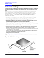
Check for damage. The foam-lined storage case provides protection during shipping.
If the case or any device appears damaged, or if the shipment is incomplete, contact
Agilent. See Table 5-1 on page 5-3. Agilent will arrange for repair or replacement of
incomplete or damaged shipments without waiting for a settlement from the
transportation company.
When you send the kit or device to Agilent, include a service tag (found near the end of this
manual) with the following information:
• your company name and address
• the name of a technical contact person within your company, and the person's complete
phone number
• the model number and serial number of the kit
• the part number and serial number of the device
• the type of service required
•a detailed description of the problem

85032B/E 1-5
General Information
Recording the Device Serial Numbers
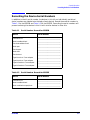
Recording the Device Serial Numbers
In addition to the kit serial number, the devices in this kit are individually serialized
(serial numbers are labeled onto the body of each device). Record these serial numbers in
Table 1-1 for the 85032B and Table 1-2 for the 85032E. Recording the serial numbers will
prevent confusing the devices in this kit with similar devices in other kits.
Table 1-1 Serial Number Record for 85032B
Device Serial Number
Calibration kit
Male broadband load
Female broadband load
Male open
Female open
Male short
Female short
Type-N-male to 7-mm adapter
Type-N-male to 7-mm adapter
Type-N-female to 7-mm adapter
Type-N-female to 7-mm adapter
_______________________________
_______________________________
_______________________________
_______________________________
_______________________________
_______________________________
_______________________________
_______________________________
_______________________________
_______________________________
_______________________________
Table 1-2 Serial Number Record for 85032E
Device Serial Number
Calibration kit
Male broadband load
Male combination open/short
_______________________________
_______________________________
_______________________________

1-6 85032B/E
General Information
Clarifying the Sex of a Connector
Clarifying the Sex of a Connector
In this manual, the sex of calibration devices and adapters are referred to in terms of their
connector interface. For example, a male open has a male connector.
However, during a measurement calibration, the network analyzer softkey menus label a
type-N calibration device with reference to the sex of the analyzer’s test port
connector—not the calibration device connector. For example, the label SHORT(F) on the
analyzer’s display refers to the short that is to be connected to the female test port. This
will be a male short from the calibration kit.
Conversely, connector gages are referred to in terms of the connector that it measures. For
instance, a male connector gage has a female connector on the gage so that it can measure
male devices.
Preventive Maintenance
The best techniques for maintaining the integrity of the devices in this kit include:
• routine visual inspection
• cleaning
• proper gaging
• proper connection techniques
All of the above are described in Chapter 3 , “Use, Maintenance, and Care of the Devices.”
Failure to detect and remove dirt or metallic particles on a mating plane surface can
degrade repeatability and accuracy and can damage any connector mated to it. Improper
connections, resulting from pin depth values being out of the observed limits (see Table 2-2
on page 2-4), or from bad connections, can also damage these devices.

85032B/E 2-1
2 Specifications

2-2 85032B/E
Specifications
Environmental Requirements
Environmental Requirements
Temperature—What to Watch Out For
Changes in temperature can affect electrical characteristics. Therefore, the operating
temperature is a critical factor in performance. During a measurement calibration, the
temperature of the calibration devices must be stable and within the range specified in
Table 2-1.
IMPORTANT Avoid unnecessary handling of the devices during calibration because your
fingers are a heat source.
Table 2-1 Environmental Requirements
Parameter Limits
Operating temperature
a
a. The temperature range over which the calibration standards maintain conformance to their
specifications.
+15 °C to +35 °C (+59 °F to +95 °F)
Error-corrected temperature range
b
b. The allowable network analyzer ambient temperature drift during measurement calibration
and during measurements when the network analyzer error correction is turned on. Also, the
range over which the network analyzer maintains its specified performance while correction
is turned on.
±1 °C of measurement calibration temperature
Storage temperature −40 °C to +75 °C (−40 °F to +167 °F)
Altitude
Operation < 4,500 meters (≈15,000 feet)
Storage < 15,000 meters (≈50,000 feet)
Relative humidity Always non-condensing
Operation 0 to 80% (26 °C maximum dry bulb)
Storage 0 to 95%

85032B/E 2-3
Specifications
Mechanical Characteristics
Mechanical Characteristics
Mechanical characteristics such as center conductor protrusion and pin depth are not
performance specifications. They are, however, important supplemental characteristics
related to electrical performance. Agilent Technologies verifies the mechanical
characteristics of the devices in this kit with special gaging processes and electrical
testing. This ensures that the device connectors do not exhibit any improper pin depth
when the kit leaves the factory.
“Gaging Connectors” on page 3-6 explains how to use gages to determine if the kit devices
have maintained their mechanical integrity. (Refer to Table 2-2 on page 2-4 for typical and
observed pin depth limits.)
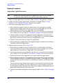
Pin Depth
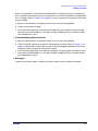
Pin depth is the distance the center conductor mating plane differs from being flush with
the outer conductor mating plane. Refer to Figure 2-1. Some coaxial connectors, such as
2.4 mm and 3.5 mm, are designed to have these planes nearly flush. Type-N connectors,
however, are designed with a pin depth offset of approximately 5.26 mm (0.207 inch), not
permitting these planes to be flush. The male center conductors are recessed by the offset
value while the female center conductors compensate by protruding the same amount.
This offset necessitates the redefining of pin depth with regard to protrusion and
recession.
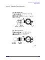
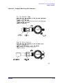
Protrusion refers to a male type-N connector center conductor having a pin depth value
less than 5.26 mm (0.207 inch), or a female type-N connector center conductor having a pin
depth value greater than 5.26 mm (0.207 inch).
Recession refers to a male type-N connector center conductor having a pin depth value
greater than 5.26 mm (0.207 in), or a female type-N connector center conductor having a
pin depth value less than 5.26 mm (0.207 inch).
Figure 2-1 Connector Pin Depth

2-4 85032B/E
Specifications
Mechanical Characteristics
NOTE The gages for measuring type-N connectors compensate for the designed
offset of 5.26 mm (0.207 inch), therefore, protrusion and recession readings
are in relation to a zero reference plane (as if the inner and outer conductor
planes were intended to be flush). Gage readings can be directly compared
with the observed values listed in Table 2-2.
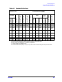
The pin depth value of each calibration device in this kit is not specified, but is an
important mechanical parameter. The electrical performance of the device depends, to
some extent, on its pin depth. The electrical specifications for each device in this kit take
into account the effect of pin depth on the device’s performance. Table 2-2 lists the typical
pin depths and measurement uncertainties, and provides observed pin depth limits for the
devices in the kit. If the pin depth of a device does not measure within the observed pin
depth limits, it may be an indication that the device fails to meet electrical specifications.
Refer to Figure 2-1 for an illustration of pin depth in type-N connectors.
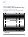
Table 2-2 Pin Depth Limit
Device Typical Pin Depth
Measurement Uncertainty
a
a. Approximately +2 sigma to −2 sigma of gage uncertainty based on studies done at the
factory according to recommended procedures.
Observed Pin Depth Limits
b
b. Observed pin depth limits are the range of observation limits seen on the gage reading due
to measurement uncertainty. The depth could still be within specifications.
Opens 0 to −0.0127 mm
0 to −0.0005 in
+0.0038 to −0.0038 mm
+0.00015 to −0.00015 in
+0.0038 to −0.0165 mm
+0.00015 to −0.00065 in
Shorts 0 to −0.0127 mm
0 to −0.0005 in
+0.0038 to −0.0038 mm
+0.00015 to −0.00015 in
+0.0038 to −0.0165 mm
+0.00015 to −0.00065 in
Fixed Loads 0 to −0.0508 mm
0 to −0.0020 in
+0.0038 to −0.0038 mm
+0.00015 to −0.00015 in
+0.0038 to −0.0546 mm
+0.00015 to −0.00215 in

85032B/E 2-5
Specifications
Electrical Specifications
Electrical Specifications
The electrical specifications in Table 2-3 apply to the devices in your calibration kit when
connected with an Agilent precision interface.
Certification
Agilent Technologies certifies that this product met its published specifications at the time
of shipment from the factory. Agilent further certifies that its calibration measurements
are traceable to the United States National Institute of Standards and Technology (NIST)
to the extent allowed by the institute’s calibration facility, and to the calibration facilities
of other International Standards Organization members. See “How Agilent Verifies the
Devices in This Kit” on page 4-2 for more information.
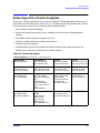
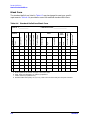
Supplemental Electrical Characteristics
Supplemental electrical characteristics are values which are typically met by a majority of
the calibration kit devices tested. These supplemental characteristics are intended to
provide information in calibration kit applications by giving typical, but non-warranted,
performance parameters. Table 2-4 lists the typical electrical characteristics of the 50Ω
loads and adapters in the 85032B/E calibration kit.
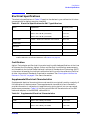
Table 2-3 Electrical Specifications for 50Ω Type-N Devices
Device Specification Frequency (GHz)
Loads Return loss ≥ 49 dB (ρ ≤ 0.00355) DC to ≤ 2
Return loss ≥ 46 dB (ρ ≤ 0.00501) > 2 to ≤ 3
Return loss ≥ 40 dB (ρ ≤ 0.01000) > 3 to ≤ 6
Female open
a
a. The specifications for the opens and shorts are given as allowed deviation from the nominal
model as defined in the standard definitions. See Table A-3 on page A-5.
±0.501 ° ±0.484 °/GHz deviation from nominal DC to ≤ 6
Female short
a
±0.490 ° ±0.385 °/GHz deviation from nominal DC to ≤ 6
Male open
a
±0.501 ° ±0.234 °/GHz deviation from nominal DC to ≤ 6
Male short
a
±0.441 ° ±0.444 °/GHz deviation from nominal DC to ≤ 6
Adapters (type-N to 7-mm) Return loss ≥ 30 dΒ (ρ ≤ 0.03162) DC to ≤ 6
Table 2-4 Supplemental Electrical Characteristics
Device Specification Frequency (GHz)
Loads Return loss ≥ 23 dΒ (ρ ≤ 0.07079) > 6 to ≤ 18
Adapters (type-N to 7-mm) Return loss ≥ 34 dΒ (ρ ≤ 0.01995) DC to ≤ 8
Return loss ≥ 28 dΒ (ρ ≤ 0.03981) > 8 to ≤ 18

2-6 85032B/E
Specifications
Electrical Specifications

85032B/E 3-1
3 Use, Maintenance, and Care of the
Devices

3-2 85032B/E
Use, Maintenance, and Care of the Devices
Electrostatic Discharge
Electrostatic Discharge
Protection against ESD (electrostatic discharge) is essential while connecting, inspecting,
or cleaning connectors attached to a static-sensitive circuit (such as those found in test
sets).
Static electricity can build up on your body and can easily damage sensitive internal
circuit elements when discharged. Static discharges too small to be felt can cause
permanent damage. Devices such as calibration components and devices under test
(DUTs), can also carry an electrostatic charge. To prevent damage to the test set,
components, and devices:
• always wear a grounded wrist strap having a 1 MΩ resistor in series with it when
handling components and devices or when making connections to the test set.
• always use a grounded, conductive table mat while making connections.
• always wear a heel strap when working in an area with a conductive floor. If you are
uncertain about the conductivity of your floor, wear a heel strap.
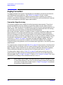
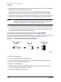
• always ground yourself before you clean, inspect, or make a connection to a
static-sensitive device or test port. You can, for example, grasp the grounded outer shell
of the test port or cable connector briefly.
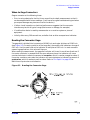
• always ground the center conductor of a test cable before making a connection to the
analyzer test port or other static-sensitive device. This can be done as follows:
1. Connect a short (from your calibration kit) to one end of the cable to short the center
conductor to the outer conductor.
2. While wearing a grounded wrist strap, grasp the outer shell of the cable connector.
3. Connect the other end of the cable to the test port.
4. Remove the short from the cable.
Refer to Chapter 6 , “Replaceable Parts,” for part numbers and instructions for ordering
ESD protection devices.
Figure 3-1 ESD Protection Setup

85032B/E 3-3
Use, Maintenance, and Care of the Devices
Visual Inspection
Visual Inspection
Visual inspection and, if necessary, cleaning should be done every time a connection is
made. Metal particles from the connector threads may fall into the connector when it is
disconnected. One connection made with a dirty or damaged connector can damage both
connectors beyond repair.
In some cases, magnification is necessary to see damage on a connector; a magnifying
device with a magnification of ≥10× is recommended. However, not all defects that are
visible only under magnification will affect the electrical performance of the connector. Use
the following guidelines when evaluating the integrity of a connector.
Look for Obvious Defects and Damage First
Examine the connectors first for obvious defects and damage: badly worn plating on the
connector interface, deformed threads, or bent, broken, or misaligned center conductors.
Connector nuts should move smoothly and be free of burrs, loose metal particles, and
rough spots.
What Causes Connector Wear?
Connector wear is caused by connecting and disconnecting the devices. The more use a
connector gets, the faster it wears and degrades. The wear is greatly accelerated when
connectors are not kept clean, or are connected incorrectly.
Connector wear eventually degrades performance of the device. Calibration devices should
have a long life if their use is on the order of a few times per week. Replace devices with
worn connectors.
The test port connectors on the network analyzer test set may have many connections each
day, and are therefore more subject to wear. It is recommended that an adapter be used as
a test port saver to minimize the wear on the test set’s test port connectors.
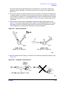
Inspect the Mating Plane Surfaces
Flat contact between the connectors at all points on their mating plane surfaces is required
for a good connection. See Figure 2-1 on page 2-3. Look especially for deep scratches or
dents, and for dirt and metal particles on the connector mating plane surfaces. Also look
for signs of damage due to excessive or uneven wear or misalignment.
Light burnishing of the mating plane surfaces is normal, and is evident as light scratches
or shallow circular marks distributed more or less uniformly over the mating plane
surface. Other small defects and cosmetic imperfections are also normal. None of these
affect electrical or mechanical performance.
If a connector shows deep scratches or dents, particles clinging to the mating plane
surfaces, or uneven wear, clean and inspect it again. Devices with damaged connectors
should be discarded. Determine the cause of damage before connecting a new, undamaged
connector in the same configuration.

3-4 85032B/E
Use, Maintenance, and Care of the Devices
Cleaning Connectors
Inspect Female Connectors
Pay special attention to the contact fingers in the female center conductor. These can be
bent or broken, and damage to them is not always easy to see. A connector with damaged
contact fingers will negatively affect electrical performance and must be replaced.
NOTE Inspection is particularly important when mating nonprecision to precision
devices.
Cleaning Connectors
Clean connectors are essential for ensuring the integrity of RF and microwave coaxial
connections.
1. Use Compressed Air or Nitrogen
WARNING Always use protective eyewear when using compressed air or
nitrogen.
Use compressed air (or nitrogen) to loosen particles on the connector mating plane
surfaces.
You can use any source of clean, dry, low-pressure compressed air or nitrogen that has
an effective oil-vapor filter and liquid condensation trap placed just before the outlet
hose.
Ground the hose nozzle to prevent electrostatic discharge, and set the air pressure to
less than 414 kPa (60 psi) to control the velocity of the air stream. High-velocity streams
of compressed air can cause electrostatic effects when directed into a connector. These
electrostatic effects can damage the device. Refer to “Electrostatic Discharge” earlier in
this chapter for additional information.
2. Clean the Connector Threads
WARNING Keep isopropyl alcohol away from heat, sparks, and flame. Store in a
tightly closed container. It is extremely flammable. In case of fire, use
alcohol foam, dry chemical, or carbon dioxide; water may be
ineffective.
Use isopropyl alcohol with adequate ventilation and avoid contact
with eyes, skin, and clothing. It causes skin irritation, may cause eye
damage, and is harmful if swallowed or inhaled. It may be harmful if
absorbed through the skin. Wash thoroughly after handling.
In case of spill, soak up with sand or earth. Flush spill area with
water.
Dispose of isopropyl alcohol in accordance with all applicable
federal, state, and local environmental regulations.
Page is loading ...
Page is loading ...
Page is loading ...
Page is loading ...
Page is loading ...
Page is loading ...
Page is loading ...
Page is loading ...
Page is loading ...
Page is loading ...
Page is loading ...
Page is loading ...
Page is loading ...
Page is loading ...
Page is loading ...
Page is loading ...
Page is loading ...
Page is loading ...
Page is loading ...
Page is loading ...
Page is loading ...
Page is loading ...
Page is loading ...
Page is loading ...
Page is loading ...
Page is loading ...
Page is loading ...
Page is loading ...
Page is loading ...
Page is loading ...
Page is loading ...
Page is loading ...
Page is loading ...
Page is loading ...
Page is loading ...
-
 1
1
-
 2
2
-
 3
3
-
 4
4
-
 5
5
-
 6
6
-
 7
7
-
 8
8
-
 9
9
-
 10
10
-
 11
11
-
 12
12
-
 13
13
-
 14
14
-
 15
15
-
 16
16
-
 17
17
-
 18
18
-
 19
19
-
 20
20
-
 21
21
-
 22
22
-
 23
23
-
 24
24
-
 25
25
-
 26
26
-
 27
27
-
 28
28
-
 29
29
-
 30
30
-
 31
31
-
 32
32
-
 33
33
-
 34
34
-
 35
35
-
 36
36
-
 37
37
-
 38
38
-
 39
39
-
 40
40
-
 41
41
-
 42
42
-
 43
43
-
 44
44
-
 45
45
-
 46
46
-
 47
47
-
 48
48
-
 49
49
-
 50
50
-
 51
51
-
 52
52
-
 53
53
-
 54
54
-
 55
55


Agilent Technologies 85032B User manual
- Category
- Networking
- Type
- User manual
- This manual is also suitable for
Ask a question and I''ll find the answer in the document
Finding information in a document is now easier with AI
Related papers
-
Agilent Technologies Work Light 85054-90049 User manual
-
-
-
-
-
-
-
-
-
Other documents
-
HP 4278A User manual
-
HP (Hewlett-Packard) Swimming Pool Gate Alarm Agilent 4194A User manual
-
Keysight Technologies 85038A 7-16 User's And Service Manual
-
-
Keysight PNA Series Network Analyzers Option 010 Time Domain Upgrade Kit Installation guide
-
-
-
-
-
Geokon 4050 User manual