Page is loading ...

MODEL
G0596/G0597/G0598/G0599
INDUSTRIAL BENCH GRINDER
OWNER'S MANUAL
COPYRIGHT © JANUARY, 2006 BY GRIZZLY INDUSTRIAL, INC.
WARNING: NO PORTION OF THIS MANUAL MAY BE REPRODUCED IN ANY SHAPE
OR FORM WITHOUT THE WRITTEN APPROVAL OF GRIZZLY INDUSTRIAL, INC.
#PC7907
PRINTED IN TAIWAN


Table of Contents
INTRODUCTION ............................................................................................................................... 2
Foreword .................................................................................................................................... 2
Contact Info ................................................................................................................................
2
Machine Data Sheet ...................................................................................................................
3
Identification ............................................................................................................................... 3
SECTION 1: SAFETY .......................................................................................................................
4
Safety Instructions for
Machinery ............................................................................................... 4
SECTION 2: CIRCUIT REQUIREMENTS ........................................................................................
7
Operation .................................................................................................................................... 7
Grounding ................................................................................................................................... 8
Extension Cords .........................................................................................................................
8
Phase Converter ........................................................................................................................
8
SECTION 3: SET UP ........................................................................................................................
9
Set Up Safety .............................................................................................................................
9
Items Needed for Set Up ........................................................................................................... 9
Unpacking .................................................................................................................................. 9
Inventory ................................................................................................................................... 10
Eye Shields .............................................................................................................................. 10
Hardware Recognition Chart ....................................................................................................
12
SECTION 4: OPERATIONS ...........................................................................................................
13
Operation Safety ......................................................................................................................
13
Wheel Care ..............................................................................................................................
14
Wheel Selection .......................................................................................................................
14
Wheel Inspection ...................................................................................................................... 15
Wheel Replacement ................................................................................................................. 16
SECTION 5: ACCESSORIES ......................................................................................................... 17
SECTION 6: SERVICE ...................................................................................................................
18
Troubleshooting ........................................................................................................................ 18
110V Wiring Diagram G0596 ...................................................................................................
19
Single Phase ............................................................................................................................
19
220V Wiring Diagram G0597/G0598 .......................................................................................
20
Single P
hase ............................................................................................................................ 20
220V Wiring Diagram G059
9 ................................................................................................... 21
3-Phase .................................................................................................................................... 21
Parts Breakdown Main .............................................................................................................
22
Parts Breakdown Shield ...........................................................................................................
23
Parts List G0596-G0597 .......................................................................................................... 24
Parts List G0598-G0599 .......................................................................................................... 25
WARRANTY AND RETURNS ........................................................................................................
26

-2-
G0596-G0599 Industrial Bench Grinders
If you have any comments regarding this manual,
please write to us at the address below:
Grizzly Industrial, Inc.
C
/O Technical Documentation Manager
P.O. Box 2069
Bellingham, WA 98227-2069
We stand behind our machines. If you have any
service questions or parts requests, please call or
write us at the location listed below.
Grizzly Industrial, Inc.
1203 Lycoming Mall Circle
Muncy, PA 17756
Phone: (570) 546-9663
Fax: (800) 438-5901
E-Mail: [email protected]
Web Site: http://www.grizzly.com
Foreword
INTRODUCTION
Contact Info
We are proud to offer the Model G0596/G0597/
G0598/G0599 Industrial Bench Grinder
. This
machine is part of a growing Grizzly family of fine
metalworking machinery. When used according
to the guidelines set forth in this manual, you can
expect years of trouble-free, enjoyable operation
and proof of Grizzly’s commitment to customer
satisfaction.
We are pleased to provide this manual with the
Model G0596/G0597/G0598/G0599. It was writ-
ten to guide you through assembly, review safety
considerations, and cover general operating pro
-
cedures. It represents our effort to produce the
best documentation possible.
The specifications, drawings, and photographs
illustrated in this manual represent the Model
G0596/G0597/G0598/G0599 as supplied when
the manual was prepared. However, owing to
Grizzly’s policy of continuous improvement,
changes may be made at any time with no obliga
-
tion on the part of Grizzly. For your convenience,
we always keep current Grizzly manuals available
on our website at
www.grizzly.com. Any updates
to your machine will be reflected in these manuals
as soon as they are complete. Visit our site often
to check for the latest updates to this manual!

G0596-G0599 Industrial Bench Grinders
-3-
MODEL G0596/G0597/G0598/G0599
Customer Service #: (570) 546-9663 • To Order Call: (800) 523-4777 • Fax #: (800) 438-5901
MACHINE DATA
SHEET
G0596
G0597 G0598 G0599
Motor HP
1 1
1
⁄2 2 3
Voltage/Phase 110, 1-PH 220V, 1-PH 220V, 1-PH 220V, 3-PH
Amps 14A 8.5A 12A 10A
RPM 1800 1800 1200 1200
Wheel Size 8 x 1 x 1" 10 x 1 x 1" 12 x 1
1
⁄2 x 1
1
⁄4" 12 x 2 x 1
1
⁄4"
Wheel Type Type 1 Type 1 Type 1 Type 1
Arbor Size
1" 1" 1
1
⁄4" 1
1
⁄4"
Height 18
1
⁄2" 18
1
⁄2" 22" 22"
Width 24" 24" 30" 30"
Depth 16" 17
1
⁄2" 19" 19"
Dust Port Diameter
2
1
⁄2" 2
1
⁄2" 3" 3"
Net Weight 118 Lbs. 132 Lbs. 220 Lbs. 226 Lbs.
Shipping Weight 140 Lbs. 155 Lbs. 264 Lbs. 270 Lbs.
Shipping Dimensions 28 x 20 x 16" 28 x 22 x 18" 34 x 24 x 20" 34 x 24 x 20"
A. Lighted Eye Shield (to be used WITH safety
glasses and face shield
)
B. Grinding Wheel
C. Tool Rest
Identification
D. ON/OFF Switch
E. Wheel Safety Guard
F. Coolant Cup
G. Dust Port
A
C
B
D
F
E
G

-4-
G0596-G0599 Industrial Bench Grinders
4. ALWAYS USE HEARING PROTECTION
WHEN
OPERATING MACHINERY.
Machinery noise can cause permanent
hearing damage.
5. WEAR PROPER APPAREL. DO NOT
wear loose clothing, gloves, neckties, rings,
or jewelry which may get caught in moving
parts. Wear protective hair covering to con
-
tain long hair and wear non-slip footwear.
6. NEVER OPERATE MACHINERY WHEN
TIRED, OR UNDER THE INFLUENCE OF
DRUGS OR ALCOHOL. Be mentally alert
at all times when running machinery.
1. READ THROUGH THE ENTIRE MANUAL
BEFORE STARTING MACHINERY.
Machinery presents serious injury hazards
to untrained users.
2. ALWAYS USE ANSI APPROVED
SAFETY GLASSES WHEN OPERATING
MACHINERY. Everyday eyeglasses only
have impact resistant lenses—they are
NOT safety glasses.
3. ALWAYS WEAR AN ANSI APPROVED
RESPIRATOR WHEN OPERATING
MACHINERY THAT PRODUCES DUST.
Wood dust is
a carcinogen and can cause
cancer and severe respiratory illnesses.
For Your Own Safety, Read Instruction
Manual Before Operating this Machine
The purpose of safety symbols is to attract your attention to possible hazardous conditions. This
manual uses a series of symbols and signal words which are intended to convey the level of
importance of the safety messages. The progression of symbols is described below. Remember
that safety messages by themselves do not eliminate danger and are not a substitute for proper
accident prevention measures.
Indicates a potentially hazardous situation which, if not avoided,
MAY result in minor or moderate injury. It may also be used to alert
against unsafe practices.
Indicates a potentially hazardous situation which, if not avoided,
COULD result in death or serious injury.
Indicates an imminently hazardous situation which, if not avoided,
WILL result in death or serious injury.
This symbol is used to alert the user to useful information about
proper operation of the machine.
NOTICE
Safety Instructions for Machinery
SECTION 1: SAFETY

G0596-G0599 Industrial Bench Grinders
-5-
7. ONLY ALLOW TRAINED AND PROP-
ERLY SUPERVISED PERSONNEL TO
OPERATE MACHINERY. Make sure
operation instructions are safe and clearly
understood.
8. KEEP CHILDREN AND VISITORS AWAY.
Keep all children and visitors a safe dis-
tance from the work area.
9. MAKE WORKSHOP CHILD PROOF. Use
padlocks, master switches, and remove
start switch keys.
10. NEVER LEAVE WHEN MACHINE IS
RUNNING. Turn power OFF and allow all
moving parts to come to a complete stop
before leaving machine unattended.
11. DO NOT USE IN DANGEROUS
ENVIRONMENTS. DO NOT use machin-
ery in damp, wet locations, or where any
flammable or noxious fumes may exist.
12. KEEP WORK AREA CLEAN AND WELL
LIT. Clutter and dark shadows may cause
accidents.
13. USE A GROUNDED EXTENSION CORD
RATED FOR THE MACHINE AMPERAGE.
Undersized cords overheat and lose power.
Replace extension cords if they become
damaged. DO NOT use extension cords
for 220V machinery.
14.
ALWAYS DISCONNECT FROM POWER
SOURCE BEFORE SERVICING
MACHINERY. Make sure switch is in
OFF
position before reconnecting.
15. MAINTAIN MACHINERY WITH CARE.
Keep blades sharp and clean for best and
safest performance. Follow instructions for
lubricating and changing accessories.
16. MAKE SURE GUARDS ARE IN PLACE
AND WORK CORRECTLY BEFORE
USING MACHINERY.
Safety Instructions for Machinery
17. REMOVE ADJUSTING KEYS AND
WRENCHES. Make a habit of checking for
keys and adjusting wrenches before turn
-
ing machinery
ON.
18. CHECK FOR DAMAGED PARTS
BEFORE USING MACHINERY. Check
for binding and alignment of parts, broken
parts, part mounting, loose bolts, and any
other conditions that may affect machine
operation. Repair or replace damaged
parts.
19. USE RECOMMENDED ACCESSORIES.
Refer to the instruction manual for recom
-
mended accessories. The use of improper
accessories may cause risk of injury.
20. DO NOT FORCE MACHINERY. Work at
the speed for which the machine or acces
-
sory was designed.
21. SECURE WORKPIECE. Use clamps or
a vise to hold the workpiece when practi-
cal. A secured workpiece protects your
hands and frees both hands to operate the
machine.
22. DO NOT OVERREACH. Keep proper foot
-
ing and balance at all times.
23. MANY MACHINES WILL EJECT THE
WORKPIECE TOWARD THE OPERATOR.
Know and avoid conditions that cause the
workpiece to "kickback."
24. ALWAYS LOCK MOBILE BASES
(IF USED) BEFORE OPERATING
MACHINERY.
25. BE AWARE THAT CERTAIN DUST MAY
BE HAZARDOUS to the respiratory sys
-
tems of people and animals, especially
fine dust. Make sure you know the hazards
associated with the type of dust you will be
exposed to and always wear a respirator
approved for that type of dust.

-6-
G0596-G0599 Industrial Bench Grinders
Additional Safety Instructions for Grinders
7. LUNG PROTECTION. Grinding produces
hazardous dust, which may cause long-
term respiratory problems. Always wear a
NIOSH–approved dust mask or respirator
when grinding.
8. SIDE GRINDING. Grinding on the side of
wheels can cause the them to break and
fly apart—unless the wheel is rated for side
grinding.
9. TOP GRINDING. Grinding on the top
of wheels greatly increases the risk of
workpiece kickback. Always grind on the
downward part of the wheel.
10. HAND/WHEEL CONTACT. Grinding
wheels can remove a lot of skin fast. Keep
a firm grip on the workpiece and position
your hands a safe distance away when
grinding. DO NOT wear gloves as they
may get caught in the grinding wheel and
cause even more serious injuries.
11. TOOL REST POSITION. If the tool rest is
too far away from the wheel, the workpiece
may be pulled down, causing loss of con
-
trol and pulling your hand into the grinding
wheel. Keep the tool rest within
1
⁄8" from the
wheel when operating.
12. CRACKED WHEEL. Cracked wheels
may break and fly apart during operation.
Replace cracked wheels immediately!
1. EYE PROTECTION. Grinding ejects small
particles at a high rate of speed. ALWAYS
wear safety glasses when using this
machine.
2. MOUNTING TO BENCH/STAND. An unse
-
cured grinder may become dangerously
out of control during operation. Make sure
grinder is FIRMLY secured to a bench/
stand before use.
3. WHEEL SPEED RATING. Wheels oper-
ated at a faster speed than rated for
may break or fly apart.
Before mount-
ing a new wheel, be sure the wheel
RPM rating is equal or higher than the
speed of the grinder.
4. WHEEL FLANGES. Only use the flanges
included with the grinder when mounting
wheels. Other flanges may not properly
secure the wheel and cause an accident.
5. RING TEST. Perform a "ring test" on grind-
ing wheels before installation to ensure
that they are safe to use. A wheel that does
not pass the ring test may break or fly apart
during operation.
6. STARTING GRINDER. If a wheel is dam
-
aged, it will usually fly apart shortly after
start-up. To protect yourself, always stand
to the side of the grinder when turning it
ON and allow it to run a full minute before
standing in front of it.
No list of safety guidelines can be complete.
Every shop environment is different. Always
consider safety first, as it applies to your
individual working conditions. Use this and
other machinery with caution and respect.
Failure to do so could result in serious per-
sonal injury, damage to equipment, or poor
work results.
Like all machinery there is potential danger
when operating this machine. Accidents are
frequently caused by lack of familiarity or
failure to pay attention. Use this machine
with respect and caution to lessen the pos
-
sibility of operator injury. If normal safety
precautions are overlooked or ignored, seri
-
ous personal injury may occur.

G0596-G0599 Industrial Bench Grinders
-7-
Serious personal injury could occur if you
connect the machine to the power source
before you have completed the set up pro
-
cess. DO NOT connect the machine to the
power source until instructed to do so.
Operation
SECTION 2: CIRCUIT REQUIREMENTS
Amperage Draw
The motor for your machine may draw the follow-
ing amps at maximum load.
G0596 at 110V Single-Phase ............... 14 Amps
G0597 at 220V Single-Phase .............. 8.5 Amps
G0598 at 220V Single-Phase ............... 12 Amps
G0599 at 220V 3-Phase ....................... 10 Amps
Circuit Requirements
We recommend connecting this machine to a
dedicated circuit with a verified ground, using the
circuit breaker size given below. Never replace a
circuit breaker with one of higher amperage with
-
out consulting a qualified electrician to ensure
compliance with wiring codes
. If you are unsure
about the wiring codes in your area or you
plan to connect your machine to a shared cir
-
cuit, you may create a fire hazard—consult a
qualified electrician to reduce this risk.
G0596 at 110V ................
15 Amp Circuit Breaker
G0597 at 220V ...............
15 Amp Circuit Breaker
G0598 at 220V ...............
15 Amp Circuit Breaker
G0599 at 220V 3-Phase .
15 Amp Circuit Breaker
Figure 1. NEMA 6-15 plug and receptacle.
Figure 2. NEMA 15-15R plug and receptacle.
Plug Type
With the exception of the G0596, the cord set
enclosed does not have a plug as the style of plug
you require will depend upon the type of service
you currently have or plan to install. We recom
-
mend using the following plugs for your machine
on a dedicated circuit only (see Figures
1–3 for
examples):
G0597 at 220V ......................... NEMA 6-15 Plug
G0598 at 220V ......................... NEMA 6-15 Plug
G0599 at 220V 3-Phase .. NEMA 15-15R Plug or
..220V Locking Shut-Off Switch (recommended)

-8-
G0596-G0599 Industrial Bench Grinders
In the event of an electrical short, grounding
reduces the risk of electric shock. The grounding
wire in the power cord must be properly connect
-
ed to the grounding prong on the plug; likewise,
the outlet must be properly installed and ground
-
ed. All electrical connections must be made in
accordance with local codes and ordinances.
We do not recommend the use of extension
cords. Instead, arrange the placement of your
equipment and the installed wiring to eliminate
the need for extension cords.
If you find it absolutely necessary to use an exten
-
sion cord with your machine, the extension cord
must also contain a ground wire and plug pin.
110V Operation
Use at least a 12 gauge cord that does not exceed
50 feet in length!
220V Operation
Use at least a 12 gauge cord that does not exceed
50 feet in length!
Extension Cords
Grounding
This machine must have a ground prong in
the plug to help ensure that it is grounded.
DO NOT remove ground prong from plug
to fit into a two-pronged outlet! If the plug
will not fit the outlet, have the proper outlet
installed by a qualified electrician.
When using a phase converter for 3-phase, the
power from the manufactured power leg (some
-
times called the wild wire) can fluctuate. Connect
the manufactured power leg to the S terminal to
prevent damage. The wire from the S terminal can
handle some fluctuation because it goes directly
to the motor. The power going to the R and T
terminals goes to the transformer and must be
consistent to prevent damage.
Phase Converter
Figure 3. A locking shut-off switch near the
machine.

G0596-G0599 Industrial Bench Grinders
-9-
The Model G0596/G0597/G0598/G0599 was
carefully packed when it left our warehouse. If
you discover the machine is damaged after you
have signed for delivery, please immediately call
Customer Service at (570) 546-9663
for advice.
Save the containers and all packing materials for
possible inspection by the carrier or its agent.
Otherwise, filing a freight claim can be difficult.
When you are completely satisfied with the con
-
dition of your shipment, you should inventory the
contents.
Wear safety glasses dur-
ing the entire set up pro
-
cess!
This machine presents
serious injury hazards
to untrained users. Read
through this entire manu
-
al to become familiar with
the controls and opera
-
tions before starting the
machine!
Unpacking
Set Up Safety
SECTION 3: SET UP
The Model G0596/G0597/
G0598/G0599 is a heavy
machine. DO NOT over-
exert yourself while
unpacking or moving
your machine—get assis-
tance.
Items Needed for
Set Up
The following items are needed to complete the
set up process, but are not included with your
machine:
Description Qty
• Wrench or Socket 12mm ............................ 1
• Wrench or Socket 8mm ..............................
1
• Safety Glasses (for each person) ..............
1
• Phillips Screwdriver #2 ...............................
1
• Assistant ..................................................
1-2

-10-
G0596-G0599 Industrial Bench Grinders
Inventory
After all the parts have been removed from the
box you should have the following items:
Box 1: Qty
A. Grinder .......................................................
1
B.
Wrench 25mm (G0596/G0597) .................. 1
C.
Wrench 50mm (G0598/G0599) .................. 1
NOTICE
Some hardware/fasteners on the inventory
list may arrive pre-installed on the machine.
Check these locations before assuming that
any items from the inventory list are miss
-
ing.
Mounting
Mount the grinder on the optional H7834 stand
(see Page 17), or a workbench that is sturdy
enough to hold the weight of the machine and
any downward pressure that may be applied dur
-
ing operation.
The stand or workbench should be level, rigid,
and attached to the floor, so it will not move dur
-
ing operation.
For proper safety, drill holes in your workbench
and secure the grinder with hex bolts, washers,
and hex nuts, or with lag screws and flat wash-
ers. (Mounting hardware is not provided due to
the many possible set ups and workbench thick
-
nesses.)
When locating your grinder, remember:
• You will need room for potentially large
workpieces.
• Maintain easy access to dust ports for attach
-
ing dust collection system.
• Grinding without dust collection system
spreads dust in the immediate vicinity of the
grinder.
• Grinding creates flying sparks that MUST be
out of reach of any flammables.
• You will need a lot of light around the
grinding wheel in addition to the lighted eye
shields.
Eye Shields
The eye shields on the Model G0596/G0597/
G0598/G0599 may come pre-mounted from the
factory. If they do not, attach them at this time with
the two Phillips head screws provided.
Figure 4. Eye shield.
Light Switch
DO NOT operate this grinder without the eye
shields or wheel guards in place. Failure
to properly use these safety devices could
lead to serious injury!
Mounting Screws

G0596-G0599 Industrial Bench Grinders
-11-
Dust Collection
The Model G0596/G0597/G0598/G0599 features
a dust port at the rear of the grinding wheel. If a
dust collection system is not attached, both ports
have spark deflectors that direct sparks down
-
ward.
To connect a dust collection hose:
1. Remove the spark deflector.
2. Fit the dust hose over the dust port, as
shown in
Figure 5, and secure in place with
a hose clamp
.
3. Tug the hose to make sure it does not come
off. Note: A tight fit is necessary for proper
performance.
Test Run
The test run ensures that the grinder and grinder
wheels were not damaged during shipping.
To test run the grinder:
1. Review and understand all grinder safety
information.
2. Remove the wheels and closely inspect the
overall conditions. Follow this by performing
a "Ring Test"
(see Wheel Inspection on
Page 15 and Wheel Replacement on Page
16).
3. Plug the grinder into the power source.
4. Put on safety glasses and face shield.
5. Stand to the side of the line of the wheels
rotation, turn the grinder
ON, and allow it to
run a least one minute, before standing in
front of it.
—The grinder should run smoothly.
—Grinding wheels should run true without
noticeable vibration.
—If there is an obvious problem with the way
the grinder is running, turn it
OFF immedi-
ately and troubleshoot the problem, using
the troubleshooting table on
Page 18. DO
NOT operate the grinder until it is fixed.
Figure 5. Dust port.
Spark Deflector
Dust Port
FIRE AND EXPLOSION HAZARD! DO NOT
attach dust ports to a dust collection system
designed or used for wood dust collection.
DO NOT operate the Model G0596/G0597/
G0598/G0599 without an adequate dust col
-
lection system. This grinder creates substan
-
tial amounts of dust while operating. Failure
to use a dust collection system can result in
short and long-term respiratory illness.

-12-
G0596-G0599 Industrial Bench Grinders
Hardware Recognition Chart

G0596-G0599 Industrial Bench Grinders
-13-
Damage to your eyes, lungs, and ears could
result from using this machine without prop
-
er protective gear. Always wear safety glass
-
es with face shield, a respirator, and hearing
protection when operating this machine.
Loose hair and cloth-
ing could get caught in
machinery and cause seri
-
ous personal injury. Keep
loose clothing and long
hair away from moving
machinery.
Grinding TipsOperation Safety
The grinder is a safe tool when used properly. In
addition to the safety instructions in this manual,
the most important safety consideration is to use
common sense at all times. What may be okay in
one situation, may not be safe in another.
Here are some tips to keep in mind while
grinding:
• DO NOT grind on the side of the wheel.
The wheels provided with the Model G0596/
G05967/G0598/G0599 are not designed for
side grinding. Grinding on the side greatly
stresses the wheel and may cause it to shat
-
ter.
• Wear the proper protective clothing. Particles
flying off of a grinding wheel will be travel
-
ing very fast—prepare for this. Wear safety
glasses/face shield, a dust mask, earplugs,
a leather apron, and heavy leather boots.
• Make sure all guards are in place.
• Remember that grinding often produces
sparks. DO NOT allow anyone to stand in
the path of the sparks. DO NOT grind near
flammable materials.
• Maintain proper care of your wheels. Read
the Wheel Care on Page 14.
• Grasp the workpiece firmly and properly
support it on the tool rest during grinding.
Maintain even pressure and control of the
workpiece when grinding.
• Concentrate on the task at hand. STOP
grinding if you are distracted.
• DO NOT grind workpieces that are heavier
than the wheel itself. This stresses the
wheel. In these cases use a handheld grind
-
er instead.
SECTION 4: OPERATIONS
NOTICE
If you have never used this type of machine
or equipment before, WE STRONGLY REC
-
OMMEND that you read books, trade maga
-
zines, or get formal training before begin
-
ning any projects. Regardless of the con
-
tent in this section, Grizzly Industrial will
not be held liable for accidents caused by
lack of training.

-14-
G0596-G0599 Industrial Bench Grinders
Wheel Care
Your safety when grinding depends, on a large
part, on the condition of the wheel during grind
-
ing. A wheel in poor condition presents the possi
-
bility of breaking apart during rotation and injuring
the operator and others in the area.
Here are some tips to help you avoid breaking
the wheel:
• Always transport, store and handle wheels
with care. Wheels may be damaged if they
are dropped or if heavy objects are stacked
on them.
• Select the right grinding wheel for the job.
DO NOT grind material inappropriate for the
wheel type.
• Select the right wheel for the machine. A
machine that rotates at a higher RPM than
the wheel is rated for may cause the wheel
to fly apart.
• Mount the wheels properly. (See the
Wheel
Replacement instructions on Page 16 for
guidance.)
• Do not abuse the wheel by jamming the work
into the grinding wheel with excessive force
that causes the grinder to bog down, or apply
pressure to stop the wheel after turning the
grinder OFF.
• Dress the wheel when necessary. Do not
allow it to become glazed.
• Always spin water/coolant out of the wheel
before turning the grinder
OFF. This may
take 5–10 minutes. (If moisture is left on the
wheel, the wheel may warp.)
• Do not store wheels in damp or wet loca
-
tions.
• Do not grind on the side of the wheel unless
wheel is designed for side grinding.
• Do not overtighten the nut when mounting
the wheel.
Wheel Selection
The Model G0596/G0597 only accepts Type 1
wheels with a 1" bore. The Model G0598/G0599
only accepts Type 1 wheels with a 1
1
⁄4" bore.
Aluminum oxide and silicon carbide wheels are
marked in a somewhat uniform manner by all the
major manufacturers. Understanding these mark
-
ings will help you understand the capabilities of
various wheels. Always refer to the manufactur
-
er’s grinding recommendations when selecting a
wheel for your project.
The basic format for wheel numbering is:
Prefix
Abrasive
Type
Grit Size Grade
Bond
Type
1 A 60 L V
The Prefix is the manufacturer’s designation for a
particular wheel type (eg, Type 1 wheels).
The most common Abrasive Types used are A
for Aluminum Oxide, C for Silicon Carbide, and
occasionally SG for Seeded Gel.
The Grit Size is a number that refers to the size
of the abrasive grain in the wheel. The lower the
number, the coarser the wheel. Ten is a very
coarse wheel for roughing and 220 is usually the
upper range for fine finish work.
Grade is an indication of the hardness of the
wheel—“A” being the softest and “Z” being the
hardest.
Bond Type refers to the type of bonding material
used to hold the abrasive material. Most general
purpose wheels will have a “V” indicating Vitrified
Clay is used. Vitrified Clay provides high strength
and good porosity. The other common bond type
is “B” for resin where synthetic resins are used.
These are used to grind cemented carbide and
ceramic materials.
Note:
There may be other numbers inserted that
have meaning for a particular type of wheel. Refer
to the manufacturer’s technical data for a com
-
plete explanation.

G0596-G0599 Industrial Bench Grinders
-15-
Wheel Inspection
Before mounting a new grinding wheel, it must
be inspected. Do not assume that a wheel is in
sound condition just because it is new—often
damage can occur in shipping, with age, or with
exposure to moisture.
First, do a Visual Inspection. Look for any
cracks, chips, nicks or dents in the surface of the
wheel. If you see any of these, DO NOT use the
wheel.
Second, do a Ring Test. This test will give you an
indication of any internal damage that may not be
obvious during a visual inspection.
To perform a Ring Test:
1. Make sure the wheel that you test is clean and
dry; otherwise, you may get false results.
2. If size permits, balance the wheel with your
finger in the hole. If this is not possible, hang
the wheel in the air with a piece of cord or
string looped through the hole in the center.
3. At the spots shown in Figure 6, gently tap
the wheel with a light non-metallic device
such as the handle of a screwdriver or a
wooden mallet.
Note: Finding the exact spot to tap will take
several attempts.
Figure 6. Tapping locations when performing a
ring test.
4. An undamaged wheel will emit a clear metal-
lic ring or “ping” sound in each of these spots.
A damaged wheel will respond with a dull
thud that has no clear tone.
5. If you determine from the ring test that the
wheel is damaged, DO NOT use it!
Wheel Dressing
Depending on the type of grinding you do, the
grinding wheel may require periodic dressing.
There are several different types of wheel dress-
ing devices available on the market (see
Page
17). Dressing restores the abrasive quality of the
wheel surface and brings the wheel edge back to
a square form.
Refer to the instructions that accompany your
dressing accessory for complete details on how
to properly dress a wheel.

-16-
G0596-G0599 Industrial Bench Grinders
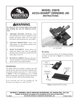
Figure 7. Assembly order for wheel installation.
NEVER assemble a grinding wheel on the
arbor without paper or fiber discs between
the wheel and the flange. Not using the
discs can put stress on the wheel, causing
it to crack and possibly fall apart.
ALWAYS visually inspect and perform a
“ring test” on a wheel before assembly. DO
NOT use damaged wheels!
6. Re-install the wheel guard.
7. Run a new wheel for at least one minute
while standing clear of the line of rotation. If
a wheel does have defects it will generally fail
within that time.
Wheel Replacement
The wheel guard must be removed in order to
mount or dismount a grinding wheel.
To replace a grinding wheel
:
1. UNPLUG THE GRINDER!
2. Remove the wheel guard.
3. Use a wrench on the arbor nut. Hold the
wheel from turning with your other hand.
Note that the wheel on the left-hand side of
the machine has left-handed threads, so the
arbor nut on that side must be turned clock
-
wise to loosen.
4. Remove the outer wheel flange and the
paper disc. Pull the wheel free from the
arbor. There will also be a paper disc and a
wheel flange on the other side of the wheel.
5. Mount the new wheel as shown in Figure
7. Always make certain there is a paper or
fiber disc between the wheel flanges and
the wheel itself. Tighten the nut snugly but
DO NOT over-tighten. Over-tightening can
crack the wheel (see Figure 8).
Figure 8. Nut removal/tightnening.
Arbor Nut

G0596-G0599 Industrial Bench Grinders
-17-
Model H7834—34
1
⁄2" Stand for Industrial
Bench Grinders
.
Model H5944—#0 Wheel Dresser
Model H5945—#1 Wheel Dresser
Model H5946—#2 Wheel Dresser
SECTION 5: ACCESSORIES
ACCESSORIES
Model H5891—
1
⁄4 Carat Diamond Dresser
Model H5892—
3
⁄4 Carat Diamond Dresser
Model G3446—Accu-Sharp Jigs
Model G4570—Accu-Sharp Stubby Chisel Jig
G0596 Replacement Wheels
Model H8880—8 x 1 x 1" Al Oxide 24 Grit
Model H8881—8 x 1 x
1" Al Oxide 36 Grit
G0597 Replacement Wheels
Model H8882—10 x 1 x 1" Al Oxide 24 Grit
Model H8883—10 x 1 x
1" Al Oxide 36 Grit
G0598 Replacement Wheels
Model H8884—12 x 1
1
⁄2 x 1
1
⁄4" Al Oxide 24 Grit
Model H8885—12 x 1
1
⁄2 x 1
1
⁄4" Al Oxide 36 Grit
G0599 Replacement Wheels
Model H8886—12 x 2 x 1
1
⁄4" Al Oxide 24 Grit
Model H8887—12 x 2
x 1
1
⁄4" Al Oxide 36 Grit
H5891
H5892

-18-
G0596-G0599 Industrial Bench Grinders
Review the troubleshooting and procedures in this section to fix your machine if a problem develops. If you
need replacement parts or you are unsure of your repair skills, then feel free to call our Technical Support
at (570) 546-9663.
SECTION 6: SERVICE
Troubleshooting
Motor & Electrical
Symptom Possible Cause Possible Solution
Motor will not start. 1. Low voltage.
2. Open circuit in motor or loose connections.
1. Check power line for proper voltage.
2. Inspect all lead connections on motor for loose or open
connections.
Motor will not start;
fuses or circuit
breakers blow.
1. Short circuit in line cord or plug.
2. Short circuit in motor or loose connections.
3. Incorrect fuses or circuit breakers in power line.
1. Inspect cord or plug for damaged insulation and shorted
wires.
2. Inspect all connections on motor for loose or shorted termi-
nals or worn insulation.
3. Install correct fuses or circuit breakers.
Motor overheats. 1. Motor overloaded. 1. Reduce load on motor.
Motor stalls (result
-
ing in blown fuses
or tripped circuit).
1. Short circuit in motor or loose connections.
2. Low voltage.
3. Incorrect fuses or circuit breakers in power line.
4. Motor overloaded.
1. Inspect connections on motor for loose or shorted terminals
or worn insulation.
2 Correct the low voltage conditions.
3. Install correct fuses or circuit breakers.
4. Reduce load on motor.
Machine slows
when operating.
1. Operator is using too much pressure. 1. Use less pressure when grinding.
Wavy condi
-
tion on surface of
workpiece.
1. Machine vibrating.
2. Workpiece not being held firmly.
3. Wheel face uneven.
4. Wheel is too hard.
1. Make sure machine is securely mounted on a solid sur-
face.
2. Use a holding device to firmly retain the workpiece.
3. Dress the grinding wheel.
4. Use softer wheel, or reduce the feed rate.
Lines on surface of
workpiece.
1. Impurity on wheel surface.
2. Workpiece not being held tightly.
1. Dress the grinding wheel.
2. Use a holding device to firmly retain the workpiece.
Burning spots
or cracks in the
workpiece.
1. Improper type of grinding wheel.
2. Improper feed rate.
3. Coolant required.
1. Try a wheel which is softer style or a coarser grit.
2. Slow down the rate of movement of the workpiece into
wheel.
3. Add optional coolant system or introduce coolant by hand.
Wheel dulls quickly,
grit falls off.
1. Depth of cut too great.
2. Wheel is too soft.
3. Wheel diameter too small.
4. Bad wheel dress.
5. Defective wheel bonding.
1. Slow down the rate of movement of the workpiece into
wheel.
2. Wheel too soft for the material being ground, select harder
bond.
3. Replace the wheel.
4. Dress the wheel.
5. Consult manufacturer of grinding wheel.
/