White Rodgers 50a55-286 User manual
- Category
- Thermostats
- Type
- User manual
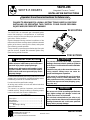
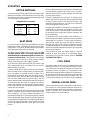
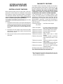
White Rodgers 50a55-286 is an automatic gas interrupted ignition control that employs a microprocessor to continually monitor, analyze, and control the proper operation of the gas burner, inducer, and fan. It can be surface mounted in any orientation and is designed to withstand temperatures from -40 to 175 degrees Fahrenheit. The 50a55-286 has multiple safety features, including a lockout time of 200 minutes, a flame establishing time of 0.8 seconds, and a flame failure response time of 2.0 seconds. Its option switches allow for customization of the heat delay-to-fan-off periods.
White Rodgers 50a55-286 is an automatic gas interrupted ignition control that employs a microprocessor to continually monitor, analyze, and control the proper operation of the gas burner, inducer, and fan. It can be surface mounted in any orientation and is designed to withstand temperatures from -40 to 175 degrees Fahrenheit. The 50a55-286 has multiple safety features, including a lockout time of 200 minutes, a flame establishing time of 0.8 seconds, and a flame failure response time of 2.0 seconds. Its option switches allow for customization of the heat delay-to-fan-off periods.


-
 1
1
-
 2
2
-
 3
3
-
 4
4
-
 5
5
-
 6
6
-
 7
7
-
 8
8


White Rodgers 50a55-286 User manual
- Category
- Thermostats
- Type
- User manual
White Rodgers 50a55-286 is an automatic gas interrupted ignition control that employs a microprocessor to continually monitor, analyze, and control the proper operation of the gas burner, inducer, and fan. It can be surface mounted in any orientation and is designed to withstand temperatures from -40 to 175 degrees Fahrenheit. The 50a55-286 has multiple safety features, including a lockout time of 200 minutes, a flame establishing time of 0.8 seconds, and a flame failure response time of 2.0 seconds. Its option switches allow for customization of the heat delay-to-fan-off periods.
Ask a question and I''ll find the answer in the document
Finding information in a document is now easier with AI
Related papers
-
White Rodgers 50A55-843 User manual
-
White Rodgers 50A55-143 User manual
-
-
-
-
-
-
-
White Rodgers 50A55-743 User manual
-
Other documents
-
ICM Controls ICM256 Application/Install Guide
-
 Honeywell Home S9200U1000 Installation guide
-
-
American Standard TUY Series Operating instructions
-
-
-
ICM Controls ICM2913 Installation guide
-
-
-
Haier HG80B11520A Owner's manual
