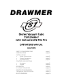
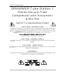
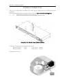
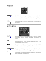
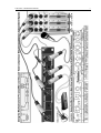
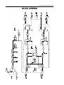
Drawmer TS1 is a high-quality stereo vacuum tube compressor with instrument & mic pre, suitable for both live sound and studio applications. It features XLR inputs and outputs, a 48V phantom power supply, a tube drive section for adding warmth and color, and a hard level limiter fixed at +16dB. The TS1 also has a built-in high-pass filter, HF contour, and a variety of attack and release settings, making it a versatile tool for a wide range of audio sources.
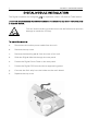
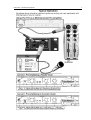
Drawmer TS1 is a high-quality stereo vacuum tube compressor with instrument & mic pre, suitable for both live sound and studio applications. It features XLR inputs and outputs, a 48V phantom power supply, a tube drive section for adding warmth and color, and a hard level limiter fixed at +16dB. The TS1 also has a built-in high-pass filter, HF contour, and a variety of attack and release settings, making it a versatile tool for a wide range of audio sources.


-
 1
1
-
 2
2
-
 3
3
-
 4
4
-
 5
5
-
 6
6
-
 7
7
-
 8
8
-
 9
9
-
 10
10
-
 11
11
-
 12
12
-
 13
13
-
 14
14
-
 15
15
-
 16
16


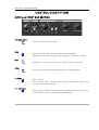
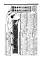
Drawmer TS1 is a high-quality stereo vacuum tube compressor with instrument & mic pre, suitable for both live sound and studio applications. It features XLR inputs and outputs, a 48V phantom power supply, a tube drive section for adding warmth and color, and a hard level limiter fixed at +16dB. The TS1 also has a built-in high-pass filter, HF contour, and a variety of attack and release settings, making it a versatile tool for a wide range of audio sources.
Ask a question and I''ll find the answer in the document
Finding information in a document is now easier with AI