Directed Electronics 480XP User manual
- Category
- Motor vehicle electronics
- Type
- User manual

480XP
Installation Guide
© 2002 Directed Electronics, Inc. Vista, CA
N552P 4-02
NOTE: This product is intended for installation by a professional installer only!
Any attempt to install this product by any person other than a trained professional
may result in severe damage to a vehicle’s electrical system and components.

Bitwriter™, Code Hopping™, DEI®, Doubleguard®, ESP™, FailSafe®, Ghost Switch™, Learn
Routine™, Nite-Lite®, Nuisance Prevention® Circuitry, NPC®, Revenger®, Silent Mode™,
Soft Chirp®, Stinger®, Valet®, Vehicle Recovery System®, VRS®, and Warn Away® are all
Trademarks or Registered Trademarks of Directed Electronics, Inc.
The Bitwriter
®
(p/n 998T)
requires chip version 1.4 or
newer to program this unit.
wwwwww..ddiirreecctteecchhss..ccoomm
DDiirreeccttFFaaxx 880000-999999-11332299 TTeecchhnniiccaall SSuuppppoorrtt 880000-775533-00880000
These resources are for authorized Directed Dealer use only.

©
2002
Directed Electronics, Inc.
3
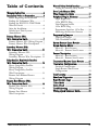
Table of Contents
WWaarrnniinngg!! SSaaffeettyy FFiirrsstt ................................................................44
IInnssttaallllaattiioonn PPooiinnttss ttoo RReemmeemmbbeerr ..............................55
Before Beginning the Installation ..........5
Finding the Tachometer Wire ...............5
Finding the WAIT-TO-START Bulb
Wire for Diesels ....................................6
After the Installation .............................6
Vehicle Anti-Theft Systems
(Immobilizers) ......................................6
PPrriimmaarryy HHaarrnneessss ((HH11))
WWiirree CCoonnnneeccttiioonn GGuuiiddee ......................................................77
Primary Harness (H1) Wiring Diagram 7
Primary Harness Wire Descriptions ......7
SSeeccoonnddaarryy HHaarrnneessss ((HH22)),,
WWiirree CCoonnnneeccttiioonn GGuuiiddee ..................................................1111
Secondary Harness (H2)
Wiring Diagram .................................11
Secondary Harness Wire Descriptions 11
RReellaayy SSaatteelllliittee KKeeyy SSwwiittcchh IInntteerrffaaccee
WWiirree CCoonnnneeccttiioonn GGuuiiddee ..................................................1122
Heavy Gauge Relay Satellite
Wiring Diagram .................................12
Heavy Gauge Relay Satellite
Wire Descriptions ...............................13
Remote Start Ribbon Harness
Wiring Diagram .................................13
RReemmoottee SSttaarrtt HHaarrnneessss ((HH33)),,
WWiirree CCoonnnneeccttiioonn GGuuiiddee ..................................................1144
Remote Start Harness (H3)
Wiring Diagram .................................14
Remote Start Harness
Wire Descriptions ...............................14
NNeeuuttrraall SSaaffeettyy SSwwiittcchh IInntteerrffaaccee ..............................1166
Testing the Neutral Safety Switch .......16
DDoooorr LLoocckk HHaarrnneessss ((HH44)),,
WWiirree CCoonnnneeccttiioonn GGuuiiddee ..................................................1177
PPeerriipphheerraall PPlluugg-IInn HHaarrnneesssseess ....................................1177
Super Bright LED,
2-Pin WHITE Plug ............................17
Valet/Program Switch,
2-Pin BLUE Plug ................................18
Programmer Interface, 3-Pin Port .......18
Mounting the Receiver/Antenna .........19
PPrrooggrraammmmiinngg JJuummppeerrss ........................................................2200
Light Flash Jumper .............................20
Tach Threshold On/Off ......................20
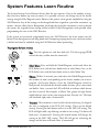
SSyysstteemm FFeeaattuurreess LLeeaarrnn RRoouuttiinnee ..............................2211
SSyysstteemm FFeeaattuurreess MMeennuuss ......................................................2233
Menu #1 - Basic Features ....................23
Menu #2 - Remote Start Features .......23
FFeeaattuurree DDeessccrriippttiioonnss ..............................................................2244
Menu #1 - Basic Features ....................24
Menu #2 - Remote Start Features .......25
TTrraannssmmiitttteerr//RReecceeiivveerr LLeeaarrnn RRoouuttiinnee ..............2277
TTrraannssmmiitttteerr CCoonnffiigguurraattiioonnss ........................................2299
Standard Configuration ......................29
Single Button Arm/Disarm
Configuration .....................................29
TTaacchh LLeeaarrnniinngg ................................................................................3300
SShhuuttddoowwnn DDiiaaggnnoossttiiccss ........................................................3300
RRaappiidd RReessuummee LLooggiicc ..............................................................3311
TTiimmeerr MMooddee ......................................................................................3311
SSaaffeettyy CChheecckk ......................................................................................3322
TTrroouubblleesshhoooottiinngg ..........................................................................3333
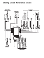
WWiirriinngg QQuuiicckk RReeffeerreennccee GGuuiiddee ..............................3366

4
©
2002
Directed Electronics, Inc.
Warning! Safety First
➤
Due to the complexity of this system, installation of this product must only be performed by an
authorized Directed dealer.
➤
When properly installed, this system can start the vehicle via a command signal from the remote
control transmitter. Therefore, never operate the system in an area that does not have adequate
ventilation. The following precautions are the sole responsibility of the user; however, authorized
Directed dealers should make the following recommendations to all users of this system:
1. Never operate the system in an enclosed or partially enclosed area without ventilation.
2. When parking in an enclosed or partially enclosed area or when having the vehicle serviced,
the remote start system must be disabled using the installed toggle switch.
3. It is the user's sole responsibility to properly handle and keep out of reach from children all
remote control transmitters to assure that the system does not unintentionally remote start.
4.
TTHHEE UUSSEERR MMUUSSTT IINNSSTTAALLLL AA CCAARRBBOONN MMOONNOOXXIIDDEE DDEETTEECCTTOORR IINN OORR
AABBOOUUTT TTHHEE LLIIVVIINNGG AARREEAA AADDJJAACCEENNTT TTOO TTHHEE VVEEHHIICCLLEE.. AALLLL DDOOOORRSS
LLEEAADDIINNGG FFRROOMM AADDJJAACCEENNTT LLIIVVIINNGG AARREEAASS TTOO TTHHEE EENNCCLLOOSSEEDD OORR
PPAARRTTIIAALLLLYY EENNCCLLOOSSEEDD VVEEHHIICCLLEE SSTTOORRAAGGEE AARREEAA MMUUSSTT AATT AALLLL TTIIMMEESS
RREEMMAAIINN CCLLOOSSEEDD..
➤
Use of this product in a manner contrary to its intended mode of operation may result in
property damage, personal injury, or death. Except when performing the Safety Check outlined
in this installation guide, (1) Never remotely start the vehicle with the vehicle in gear, and (2)
Never remotely start the vehicle with the keys in the ignition. The user will be responsible for
having the neutral safety feature of the vehicle periodically checked, wherein the vehicle must
not remotely start while the car is in gear. This testing should be performed by an authorized
Directed dealer in accordance with the Safety Check outlined in this product installation guide.
If the vehicle starts in gear, cease remote start operation immediately and consult with the user
to fix the problem immediately.
➤
After the remote start module has been installed, test the remote start module in accordance with
the Safety Check outlined in this installation guide. If the vehicle starts when performing the
Neutral Safety Shutdown Circuit test, the remote start unit has not been properly installed. The
remote start module must be removed or properly reinstalled so that the vehicle does not start in
gear. All installations must be performed by an authorized DEI dealer.
OOPPEERRAATTIIOONN OOFF TTHHEE
RREEMMOOTTEE SSTTAARRTT MMOODDUULLEE IIFF TTHHEE VVEEHHIICCLLEE SSTTAARRTTSS IINN GGEEAARR IISS
CCOONNTTRRAARRYY TTOO IITTSS IINNTTEENNDDEEDD MMOODDEE OOFF OOPPEERRAATTIIOONN.. OOPPEERRAATTIINNGG TTHHEE
RREEMMOOTTEE SSTTAARRTT SSYYSSTTEEMM UUNNDDEERR TTHHEESSEE CCOONNDDIITTIIOONNSS MMAAYY RREESSUULLTT IINN
PPRROOPPEERRTTYY DDAAMMAAGGEE OORR PPEERRSSOONNAALL IINNJJUURRYY.. IIMMMMEEDDIIAATTEELLYY CCEEAASSEE TTHHEE
UUSSEE OOFF TTHHEE UUNNIITT AANNDD RREEPPAAIIRR OORR DDIISSCCOONNNNEECCTT TTHHEE IINNSSTTAALLLLEEDD
RREEMMOOTTEE SSTTAARRTT MMOODDUULLEE.. DDIIRREECCTTEEDD WWIILLLL NNOOTT BBEE HHEELLDD RREESSPPOONNSSIIBBLLEE
OORR PPAAYY FFOORR IINNSSTTAALLLLAATTIIOONN OORR RREEIINNSSTTAALLLLAATTIIOONN CCOOSSTTSS..

©
2002
Directed Electronics, Inc.
5
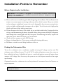
Installation Points to Remember
Before Beginning the Installation
➤
Please read this entire installation guide before beginning the installation. The installation of this
remote start system requires interfacing with many of the vehicle’s systems. Many new vehicles
use low-voltage or multiplexed systems that can be damaged by low-resistance testing devices,
such as test lights and logic probes (computer safe test lights). Test all circuits with a high-quality
digital multi-meter before making connections.
➤
Do not disconnect the battery if the vehicle has an anti-theft-coded radio. If equipped with an
air bag, avoid disconnecting the battery if possible. Many airbag systems will display a diagnostic
code through their warning lights after they lose power. Disconnecting the battery requires this
code to be erased, which can require a trip to the dealer.
➤
Check with the customer on status LED location.
➤
Remove the domelight fuse. This prevents accidentally draining the battery.
➤
Roll down a window to avoid being locked out of the car.
Finding the Tachometer Wire
To test for a tachometer wire, a multimeter capable of testing AC voltage must be used. The
tachometer wire will show between 1V and 6V AC. In multi-coil ignition systems, the system can
learn individual coil wires. Individual coil wires in a multi-coil ignition system will register lower
amounts of AC voltage. Also, if necessary, the system can use a fuel injector control wire for engine
speed sensing.
Common locations for a tachometer wire are the ignition coil, instrument cluster, fuel injectors, or
engine computers.
IMPORTANT! Do not test tachometer wires using a test light or logic probe! This will
damage the vehicle.
IMPORTANT! This product is designed for fuel-injected, automatic transmission
vehicles only. Installing it in a standard transmission vehicle is dangerous and is
contrary to its intended use.

6
©
2002
Directed Electronics, Inc.
How to find a tachometer wire with your multimeter:
1. Set to ACV or AC voltage (12V or 20V is fine).
2. Attach the (-) probe of the meter to chassis ground.
3. Start and run the vehicle.
4. Probe the wire you suspect of being the tachometer wire with the red probe of the meter.
5. If this is the correct wire the meter will read between 1V and 6V.
Finding the WAIT-TO-START Bulb Wire for Diesels
In diesel vehicles it is necessary to interface with the wire that turns on the WAIT TO START light
in the dashboard. This wire illuminates the bulb until the vehicle’s glow plugs are properly heated.
When the light goes out the vehicle can be started. This wire is always available at the connector
leading to the bulb in the dashboard. It can also be found at the Engine Control Module (ECM)
in many vehicles.
To test and determine the polarity of this wire:
1. Set your multimeter to DCV or DC voltage (12 or 20V is fine).
2. Attach the (+) probe of the meter to (+)12V.
3. Probe the wire that you suspect leads to the bulb with the (-) probe of the meter.
4. Turn the ignition switch to the ON position.
5. If the meter indicates 12 volts until the light goes out you have isolated the correct wire and the
wire's polarity is negative (ground while the bulb is on).
6. If the meter reads zero volts until the light goes out and then reads 12 volts, you have isolated
the correct wire and the wire's polarity is positive.
After the Installation
➤
Test all functions. The Using Your System section of the Owner's Guide is very helpful when
testing.
➤
Review and complete the Safety Check section of this guide prior to the vehicle reassembly.
Vehicle Anti-Theft Systems (Immobilizers)
Vehicle anti-theft systems (immobilizers) require a bypass module. The bypass module allows for
easy interfacing, while still maintaining the OEM security system’s integrity. For vehicle listings and
required bypass, see DirectFax Document 1059, available only to authorized dealers though the
technical resources listed at the front of this guide.

©
2002
Directed Electronics, Inc.
7
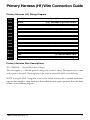
Primary Harness (H1) Wire Connection Guide
Primary Harness (H1) Wiring Diagram
___
___
___
___
___
___
___
___
___
___
___
___
Primary Harness Wire Descriptions
H1/1 ORANGE (-) Ground-When-Armed Output
This wire supplies a (-) 500 mA ground as long as the system is armed. This output ceases as soon
as the system is disarmed. The orange wire is pre-wired to control the 8618 starter kill relay.
NOTE: if using the H1/1 Orange wire to activate an add-on accessory such as window automation,
pager or voice module a 1Amp diode must be installed to ensure proper operation. Insert the diode
as shown in the following diagram.
RED/WHITE (-) 200 mA Channel 2 Programmable Output
RED (+) Constant Power Input
BROWN (-) Horn Honk Output
OPEN No Wire
BLACK (-) Chassis Ground Input
VIOLET No Function
BLUE No Function
GREEN No Function
BLACK/WHITE (-) 200 mA Domelight Supervision Output
WHITE/BLUE (-) Remote Start Activation Input
WHITE (+)/(-) Selectable Light Flash Output
ORANGE (-) 500 mA Armed Output
H1/1
H1/2
H1/3
H1/4
H1/5
H1/6
H1/7
H1/8
H1/9
H1/10
H1/11
H1/12

8
©
2002
Directed Electronics, Inc.
H1/2 WHITE (+/-) Selectable Light Flash Output
As shipped, this wire should be connected to the (+) parking light wire. If the light flash polarity
jumper is moved to the (-) position (see the Programming Jumper section of this guide), this wire
supplies a (-) 200 mA output. This is available for driving (-) light control wires in Toyota, Lexus,
BMW, some Mitsubishi, some Mazda, and other models.
NOTE: For parking light systems that draw 10 amps or more, the jumper must be switched to a
(-) light flash output. (See the Programming Jumpers section of this guide.) P/N 8617 or a standard
automotive SPDT relay must be used on the H1/2 light flash output wire.
IMPORTANT! DO NOT connect this wire to a negative vehicle light flash wire before
changing the programming jumper to the negative polarity position or damage to
vehicle light circuit may occur.
IMPORTANT! Never interrupt any wire other than the starter wire.

©
2002
Directed Electronics, Inc.
9
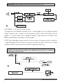
H1/3 WHITE/BLUE Activation Input
A momentary input on this wire will start or stop the motor, just as transmitting Channel 3 from
the remote transmitter does. It is often connected to an optional momentary push-button switch to
make activating Valet Take Over more convenient.
H1/4 BLACK/WHITE (-) 200 mA Domelight Supervision Output
Connect this wire to the optional domelight supervision relay as shown in the following diagram:
H1/8 BLACK (-) Chassis Ground Connection
Connect this wire to a clean, paint-free sheet metal location (driver kick panel) using a factory bolt
that DOES NOT have any vehicle component grounds attached to it. A screw should only be used
when in conjunction with a two-sided lock washer. Under dash brackets and door sheet metal are
not acceptable ground points. It is recommended that all security components be grounded at the
same location.
IMPORTANT! This output is only intended to drive a relay. It cannot be connected
directly to the domelight circuit, as the output cannot support the current draw of one
or more bulbs.

10
©
2002
Directed Electronics, Inc.
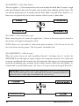
H1/10 BROWN (+) Horn Honk Output
This wire supplies a (-) 200 mA output that can be used to honk the vehicle horn. It outputs a single
pulse when locking the doors with the remote, and two pulses when unlocking with the remote. This
wire will also output pulses for 30 seconds when the Panic Mode is activated. If the vehicle has a (+)
horn circuit, an optional relay can be used to interface with the system, as shown below.
H1/11 RED (+)12V constant power input
Before connecting this wire, remove the supplied fuse. Connect to the battery positive terminal or
the constant 12V supply to the ignition switch.
NOTE: Always use a fuse within 12 inches of the point you obtain (+)12V. Do not use the 15A
fuse in the harness for this purpose. This fuse protects the module itself.
H1/12 RED/WHITE (-) 200 mA output
When the system receives the code controlling Channel 2, for longer than 1.5 seconds, the
RED/WHITE wire will supply an output as long as the transmission continues. This is often used
to operate a trunk/hatch release or other relay-driven function. This output can also be programmed
to provide the following types of output: Instant validity, latched, latched-reset with ignition, 30-
second timed, or second unlock output. (See Features Description section of this guide for details.)
IMPORTANT! Never use this wire to drive anything but a relay or a low-current input!
The transistorized output can only supply 200 mA of current. Connecting directly to a
solenoid, motor, or other high-current device will cause it to fail.

©
2002
Directed Electronics, Inc.
11
Secondary Harness (H2),
Wire Connection Guide
Secondary Harness (H2) Wiring Diagram
___
___
Secondary Harness Wire Descriptions
H2/1 GRAY/BLACK (-) Diesel Wait-to-Start Bulb Input
Connect this wire to the wire in the vehicle that sends the signal to turn on the WAIT-TO-START
bulb in the dashboard. In most diesels the wire is negative (ground turns on the bulb) and the
GRAY/BLACK can be directly connected to the wire in the vehicle. If the vehicle uses a positive
wire (12V to turn on the bulb) a relay must be used to change the polarity. (See Finding the Wait-
To-Start Bulb Wire For Diesels section of this guide.) Here are some common colors of this wire:
➤
Chevrolet and GMC trucks: Light Blue or Dark Blue
➤
Ford Trucks: Black/Pink
➤
Dodge Ram Trucks: Orange/Black or Black/Orange
NOTE: A 1-amp diode must be installed in line on the factory wire between the wait-to-start
indicator and the ECM. (See the following diagram for details.)
LIGHT GREEN/BLACK (-) Factory Disarm/Special Accessory
GRAY/BLACK (-) Wait-to-Start Input
H2/1
H2/2

12
©
2002
Directed Electronics, Inc.
H2/2 LIGHT GREEN/BLACK (-) Auxiliary Output
This wire sends a negative pulse every time the remote start is activated. This can be used to pulse
the disarm wire of the vehicle's factory anti-theft device. Use a relay to send a (-) or (+) pulse to the
disarm wire as shown in the diagrams below. This wire can also be used as a special accessory output.
(See Feature Descriptions section of this guide.)
RReellaayy ffoorr NNeeggaattiivvee ((-)) DDiissaarrmm WWiirree RReellaayy ffoorr PPoossiittiivvee ((++)) DDiissaarrmm WWiirree
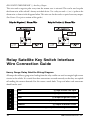
Relay Satellite Key Switch Interface
Wire Connection Guide
Heavy Gauge Relay Satellite Wiring Diagram
All except the red heavy gauge wires leading from the relay satellite are used to energize high current
circuits in the vehicle. It is crucial that these connections are made correctly so that they are capable
of handling the current demands. For this reason, scotch locks, T-taps and other such connectors
should not be used.
___
___
___
___
___
___
PINK/WHITE (+) Output to Second Ignition Circuit
PURPLE (+) Output to Starter Circuit
ORANGE (+) Output to Accessory Circuit
PINK (+) Output to Ignition Circuit
RED (+) High Current 12V Input
RED (+) High Current 12V Input
1
2
3
4
5
6

©
2002
Directed Electronics, Inc.
13
Heavy Gauge Relay Satellite Wire Descriptions
RED (2) (+)12V Input for Relays
Remove the two 30 amp fuses prior to connecting these wires and do not replace them until the
satellite has been plugged into the control module. These wires are the source of current for all the
circuits the relay satellite will energize. They must be connected to a high current source. Since the
factory supplies (+) 12V to the key switch that is used to operate the motor, it is recommended that
these wires be connected there.
NOTE: If the factory supplies two separate (+) 12V feeds to the ignition switch, connect one RED
wire of the satellite to each feed at the switch.
PINK (+) Ignition Output
Connect this wire to the ignition wire in the vehicle.
ORANGE (+) Accessory Output
Connect this wire to the accessory wire in the vehicle that powers the climate control system.
PURPLE (+) Starter Output
Connect this wire to the starter wire in the vehicle.
PINK/WHITE (+) Output to Second Ignition Circuit
Connect this wire to the second ignition wire in the vehicle.
NOTE: For vehicles that do not have a second ignition wire, this connection is not required.
Remote Start Ribbon Harness Wiring Diagram
___
___
___
___
___
RED (+) Constant Power
YELLOW (+) Ignition Input to Remote Start
PINK (-) 200 mA Ignition Relay Turn-On
ORANGE (-) 200 mA Accessory Relay Turn-On
PURPLE (-) 200 mA Starter Relay Turn-On
1
2
3
4
5

14
©
2002
Directed Electronics, Inc.
Remote Start Harness (H3),
Wire Connection Guide
Remote Start Harness (H3) Wiring Diagram
___
___
___
___
___
___
Remote Start Harness Wire Descriptions
H3/1 BLUE Status/Factory Security Rearm Output
This wire supplies a 200mA output as soon as the module begins the remote start process. The H3/1
BLUE wire can also be used to rearm a factory anti-theft system when the remote start shuts down.
(See the Feature Descriptions section in this guide.)
H3/2 BLUE/BLACK (-) Optional Third Ignition Output
This output provides 200mA as soon as the remote starter is activated. It can be used to power a
relay to energize a positive (+) third ignition as shown below. This output is capable of driving two
relays if necessary.
H3/3 GRAY (-) Hood Pinswitch Input
This wire MUST be connected to hood pinswitch. This input will disable or shut down the remote
start when the hood is opened.
BLACK/WHITE (-) Neutral Safety Switch Input
VIOLET/WHITE Tachometer Input Wire
BROWN (-) Brake Switch Shutdown Wire
GRAY (-) Hood Pinswitch Shutdown Wire
BLUE/BLACK (-) 200 mA Optional Third Ignition Output
BLUE (-) Status/Factory Security Rearm Output
1
2
3
4
5
6

©
2002
Directed Electronics, Inc.
15
H3/4 BROWN (+) Brake Switch Input
This wire MUST be connected to the vehicle's brake light wire. This is the wire that shows (+) 12V
when the brake pedal is pressed. The remote start will be disabled or shut down any time the brake
pedal is pressed.
H3/5 VIOLET/WHITE Tachometer Input
This input provides the module with information about the engine's revolutions per minute
(RPMs). It can be connected to the negative side of the coil in vehicles with conventional coils. In
multi-coil and high energy ignition systems locating a proper signal may be more difficult. (See
Installation Points to Remember section of this guide for finding the tachometer wire.) Once
connected, you must teach the system the tach signal. (See Tach Learning section of this guide.)
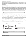
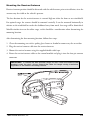
H3/6 BLACK/WHITE Neutral Safety Switch Input
Connect this wire to the toggle (override) switch as shown in Figure A. Connect the other wire from
the toggle switch to the park/neutral switch in the vehicle. This wire will test with ground with the
gear selector either in PARK or NEUTRAL. This will prevent the vehicle from accidentally being
started while in a drive gear. This input MUST rest at ground in order for the remote start system
to operate. Connected properly the vehicle will only start while in PARK or NEUTRAL.
In some vehicles, the park/neutral position switch activates a factory starter lock out that will not
allow the starter to operate in a drive gear. In these vehicles, connect this wire to the toggle switch
as shown in Figure B. Connect the other wire from the toggle switch to chassis ground.
Figure A Figure B
IMPORTANT! Always perform the Vehicle Safety Check section of this guide to verify
that the vehicle cannot be started in ANY drive gear and that the override switch is
functioning properly.
IMPORTANT! DO NOT use T-Taps or scotch locks for this connection.

16
©
2002
Directed Electronics, Inc.
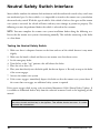
Neutral Safety Switch Interface
Some vehicles combine the column shift mechanism and the mechanical neutral safety switch into
one mechanical part. In these vehicles, it is impossible to interface the remote start system before
the neutral safety switch. With this type of vehicle, if the vehicle is left in a drive gear and the remote
start system is activated, the vehicle will move and may cause damage to persons or property. The
following test must be performed before the vehicle is released to the customer.
NOTE:
You must complete the remote start system installation before doing the following test.
Ensure that the remote start system is functioning normally. This includes connecting to the brake
as a shut-down.
Testing the Neutral Safety Switch
1. Make sure there is adequate clearance to the front and rear of the vehicle because it may move
slightly.
2. Make sure the hood is closed and there are no remote start shut-downs active.
3. Set the emergency brake.
4. Turn the key to the "run" position, this will release the shifter.
5. Place the car in drive (D).
6. Place your foot directly over the brake pedal, but do not depress it. Be ready to step on the brake
if the starter engages.
7. Activate the remote start system.
8. If the starter engages, immediately depress the brake to shut the remote start system down. If
the starter does not engage, no additional safety system is required.
If the starter engages while testing, refer to technical document #1008 (Neutral Safety Update). It
is available to authorized dealers only from the technical resources listed at the beginning of this
manual.
IMPORTANT! Once the interface is complete, attempt to remote start the vehicle with
the door closed and the key in the ignition. The vehicle should not start. If it does,
recheck the connections.

©
2002
Directed Electronics, Inc.
17
Door Lock Harness (H4),
Wire Connection Guide
___
___
___
NOTE: For detailed instructions about connecting to the vehicle’s power door lock systems, refer
to the Door Lock Wiring guide (Document No. 1041) available only to authorized dealers though
the technical resources listed at the front of this guide.
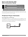
Peripheral Plug-In Harnesses
Super Bright LED, 2-Pin WHITE Plug
The super bright LED operates at (+) 2 volt DC and plugs into the two-pin WHITE port. Make
sure the LED wires are not shorted to ground as the LED will be damaged. Multiple LED’s can be
used, but they must be wired in series. The LED fits into a 9/32-inch mounting hole. Be sure to
check for clearance prior to drilling the mounting hole.
DIA-41
IMPORTANT! The door lock outputs are low current and should not be attached
directly to any high current device; they are only to be used to activate relays
Blue (-) Unlock, (+) Lock Output
Empty Unless Using 451M
Green (-) Lock, (+) Unlock Output
H2/A
H2/B
H2/C

18
©
2002
Directed Electronics, Inc.
Valet/Program Switch, 2-Pin BLUE Plug
The Valet/Program button should be accessible from the driver’s seat. It plugs into the BLUE port
on the side of the unit. Consider how the button will be used before choosing a mounting location.
Check for rear clearance before drilling a 9/32-inch hole and mounting the button.
Programmer Interface, 3-Pin Port
The BLACK three-pin port is provided for programming of the unit. When using the 998T
Bitwriter, it is possible to configure any and all of the programmable functions. For more infor-
mation please refer to the guide packaged with the programmer.

©
2002
Directed Electronics, Inc.
19
Mounting the Receiver/Antenna
Receiver/antenna position should be discussed with the vehicle owner prior to installation, since the
antenna may be visible to the vehicle’s operator.
The best location for the receiver/antenna is centered high on either the front or rear windshield.
For optimal range, the antenna should be mounted vertically. It can be mounted horizontally in
relation to the windshield or under the dashboard away from metal, but range will be diminished.
Metallic window tint can also affect range, so this should be a consideration when determining the
mounting location.
After determining the best mounting location, follow these steps:
1. Clean the mounting area with a quality glass cleaner or alcohol to remove any dirt or residue.
2. Plug the receiver/antenna cable into the receiver/antenna.
3. Mount the receiver/antenna using the supplied double-sided tape.
4. Route the receiver/antenna cable to the control module and plug it into the four-pin antenna
connector.
IMPORTANT! To achieve the best possible range, DO NOT leave the antenna cable
bundled under the dash. Always extend the cable full length during installation,
regardless of the antenna mounting location.

20
©
2002
Directed Electronics, Inc.
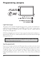
Programming Jumpers
Light Flash Jumper
This jumper is used to determine the light flash output. In the (+) position, the on-board relay is
enabled and the unit will output (+)12V on the WHITE wire, H1/2. In the (-) position, the on-
board relay is disabled. The WHITE wire, H1/2, will supply a 200 mA (-) output suitable for
driving factory parking light relays.
NOTE: For parking light circuits that draw 10 amps or more, the jumper must be switched to a (-)
light flash output. P/N 8617 or a standard automotive SPDT relay must be used on the H1/2 light
flash output harness wire.
Tach Threshold On/Off
In most cases, this jumper can be left in the OFF position. Some new vehicles use less than 12 volts
in their ignition systems. The unit may have trouble learning the tach signal in these vehicles.
Changing the jumper to the ON setting changes the trigger threshold of the digital tach circuit so
it will work properly with these vehicles. The vehicles affected include many newer
Dodge/Chrysler/Plymouth vehicles, such as the Neon, Cirrus, Stratus, Breeze and LH-based
vehicles.
IMPORTANT! DO NOT connect the H1/2 light flash wire to a negative vehicle light
flash wire before changing the programming jumper to the negative polarity position or
damage to vehicle light circuit may occur.
Page is loading ...
Page is loading ...
Page is loading ...
Page is loading ...
Page is loading ...
Page is loading ...
Page is loading ...
Page is loading ...
Page is loading ...
Page is loading ...
Page is loading ...
Page is loading ...
Page is loading ...
Page is loading ...
Page is loading ...
Page is loading ...
-
 1
1
-
 2
2
-
 3
3
-
 4
4
-
 5
5
-
 6
6
-
 7
7
-
 8
8
-
 9
9
-
 10
10
-
 11
11
-
 12
12
-
 13
13
-
 14
14
-
 15
15
-
 16
16
-
 17
17
-
 18
18
-
 19
19
-
 20
20
-
 21
21
-
 22
22
-
 23
23
-
 24
24
-
 25
25
-
 26
26
-
 27
27
-
 28
28
-
 29
29
-
 30
30
-
 31
31
-
 32
32
-
 33
33
-
 34
34
-
 35
35
-
 36
36


Directed Electronics 480XP User manual
- Category
- Motor vehicle electronics
- Type
- User manual
Ask a question and I''ll find the answer in the document
Finding information in a document is now easier with AI
Related papers
-
Directed Electronics RSIII User manual
-
-
Directed Electronics 560XV Installation guide
-
-
Directed Electronics 791 XV Installation guide
-
-
Directed Electronics Python 990 User manual
-
-
-
Other documents
-
Viper 790XV Installation guide
-
 Hornet 554T Installation guide
-
Kyosho LED Light Set (No.CA0506) User manual
-
Clarion UNGO PRO SECURITY SYSTEM K20 Installation guide
-
Avital 3200 Installation guide
-
-
Python 881 XP Installation guide
-
-
-
