
OPERATING INSTRUCTIONS AND OWNER’S MANUAL
READ INSTRUCTIONS CAREFULLY: Read and follow all
instructions. Place instructions in a safe place for future
reference. Do not allow anyone who has not read these
instructions to assemble, light, adjust or operate the heater.
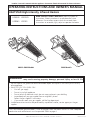
HEATSTAR High-Intensity Infrared Heaters
HS4040 HS9100S
HS8060 HS9120
MODELS
Installer: Leave this manual with the appliance. Consumer: Retain this manual for future reference.
If the information in this manual is not followed exactly, a fire or explosion
may result causing property damage, personal injury or loss of life.
WARNING:
— Do not store or use gasoline or other flammable vapors and liquids in the vicinity of this or any
other appliance.
— WHAT TO DO IF YOU SMELL GAS
• Shutoffgassupply
• Donottrytolightappliance
• Donottouchanelectricalswitch;donotuseanyphoneinyourbuilding
• Immediatelycallyourgassupplierfromaneighbor’sphone.
Followthegassupplier’sinstructions
• Ifyoucannotreachyourgassupplier,calltheredepartment
—Installationandservicemustbeperformedbyaqualiedinstaller,serviceagencyorthegas
supplier.
Thisisanunventedgas-redheater.Itusesair(oxygen)fromtheareainwhichitisused.Adequate
combustion and ventilation air must be provided. Refer to page 4.
ENERCOGROUPINC.,4560W.160THST.,CLEVELAND,OHIO44135•216-916-3000
4000 & 8000 Models 9000 Models
18650 Rev. A 06/08

2
Enerco Group, Inc. |Gas-Fired Infra-Red Space Heaters OperatingInstructionsandOwner’sManual
CONTENTS
General Information .......................................................... 3
Clearances ........................................................................ 3
Gas Supply ........................................................................ 3
Gas Pressure ..................................................................... 3
Electrical ........................................................................... 4
Thermostat & Location ...................................................... 4
Ventilation ........................................................................ 4
Operations ........................................................................4
Cleaning Information ........................................................ 4
Connection diagram for flame rod current
foramerecticationsystems ......................................5
Thermostat ....................................................................... 5
Replacement parts ............................................................7
Control system replacement parts ................................... 10
WARNING: Improper installation, adjustment,
alteration, service or maintenance can cause property
damage, injury or death. Read the installation, opera-
tion, and maintenance instructions thoroughly before
installing or servicing this equipment. For assistance
oradditionalinformationconsultaqualiedinstaller,
service agency, or gas supplier.
WARNING: When used without fresh air, heater
may give off CARBON MONOXIDE, an odorless poi-
sonous gas. OPEN WINDOW AN INCH OR TWO FOR
FRESH AIR WHEN USING HEATER.
WARNING: This heater is equipped with a PILOT
LIGHT SAFETY SYSTEM. DO NOT TAMPER WITH PILOT
LIGHT SAFETY SYSTEM.
WARNING: If heater shuts off, do not relight
until you provide fresh air. If heater keeps shutting off,
have it serviced. Keep burner and control clean. Open
door for 5 minutes.
Maintain clearances as shown in Figure 1 or on heater nameplate.
•DONOTUSEMATCHOROTHERFLAME
FOR LEAK TESTING.
•DONOTEXCEED1/2PSIINLETPRESSURETOHEATER.
DANGER:
Carbonmonoxidepoisoningmayleadtodeath.
Carbon Monoxide Poisoning:
Earlysignsofcarbonmonoxidepoisoningresemble
the flu, with headaches, dizziness, or nausea. If you
have these signs, the heater may not be working
properly. Get fresh air at once! Have heater serviced.
Somepeoplearemoreaffectedbycarbonmonoxide
than others. These include pregnant women, persons
with heart or lung disease or anemia, those under the
influence of alcohol, and those at high altitudes.
CAUTION:
•Neverconnectgasvalveorthermostattolinevoltage
or a transformer.
•Iftheinfra-redcolorofthegridbecomesdullwhen
the building furnace is operating, consult gas supplier
on correct gas supply piping sizes.
•Thisheaterisforindoorinstallationonly!
NOTE Gasket binder material used in this heater assem-
bly will temporarily emit an odor and/or vapor. This
conditionwillclearupinapproximately20minutes
and thereafter will not reoccur. Refer to page 4 for
ventilation.
THE STATE OF CALIFORNIA REQUIRES THE
FOLLOWING WARNING:
WARNING: Combustion by-products produced
whenusingthisproductcontaincarbonmonoxide,
a chemical known to the State of California to cause
cancerandbirthdefects(orotherreproductiveharm).

3
OperatingInstructionsandOwner’sManualEnerco Group, Inc. | Gas-Fired Infra-Red Space Heaters
1. GENERAL INFORMATION
Your heater comes fully assembled and is tested at a.
the factory for proper gas and input as stated on
the name plate.
Before proceeding with the installation, be sure to b.
inspect for damages. Freight company must be noti-
edofanydamagesandrequestthataninspection
be made by the freight company. HEAT STAR will send
replacement parts for damaged parts only after receiv-
ing a signed inspection report to prove the liability of
the freight company.
Do not attempt to operate heater with any other gas c.
than that indicated on the heater name plate.
The installation of heater must conform with local d.
building codes or, in absence of local codes, with the
National Fuel Gas Code, ANSI Z223.1a/NFPA54. In
Canada, refer to Can 1-B146.1 and B149.2.
Plugged 1/8” N.P.T. Test Gage Connection is located e.
on the Heater Gas Control or a ¼” N.P.T. Connection is
located on the outside of the Cast Venturi.
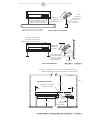
2. CLEARANCES Minimum clearances to combustibles.
(Refer to Figure 1)
Provide adequate clearance to combustibles, Figure 1,
between control end of heater for servicing and mini-
mum on top and sides for ventilation and combustion
air supply.
Aminimumclearanceof8’aboveoorforpublic
garages in accordance with ANSI/NFPA No. 88 most re-
centeditionorFigure1;whicheverislarger.InCanada
refer to Can 1-B149.1 and B149.2 Installation codes for
Gas burning appliances.
Aminimumclearanceof10’fromthebottomofheater
to top of wing, or engine enclosure, where aircraft are
housed,and8’aboveoorinotherareasofthehang-
er in accordance with ANSI/NFPA No. 409 most recent
FIGURE 1
MODEL NO.
BTU/HR. RATING
NORMAL
MOUNTING
POSITION
CLEARANCES TO COMBUSTIBLES
GAS
NATURAL PROPANE TOP SIDES BACK BELOW
4030** 30,000 30,000 Horiz.-45° 30” 30” 30” 54”
4040* 40,000 40,000 Horiz.-45° 34” 30” 30” 68”
8050** 50,000 50,000 Horiz.-45° 36” 30” 30” 78”
8060* 60,000 60,000 Horiz.-45° 40” 30” 30” 84”
8070** 70,000 – Horiz.-45° 40” 30” 30” 84”
9080** 80,000 80,000 Horiz.-45° 46” 40” 40” 104”
9090** 90,000 90,000 Horiz.-45° 46” 46” 46” 114”
9100S* 100,000 100,000 Horiz.-45° 48” 46” 46” 118”
9100** 100,000 100,000 Horiz.-45° 44” 40” 40” 104”
9120* 120,000 120,000 Horiz.-45° 46” 46” 46” 114”
9140** 140,000 – Horiz.-45° 16” 46” 46” 114”
edition,orFigure1;thelargerdimensionofANSI/NFPA
No. 409 or Figure 1 is to be used. In Canada refer to
CCA B149-1-M91 and B149.2.
WARNING: MAINTAIN CLEARANCES AS SHOWN
IN FIGURE 1 OR ON HEATER NAMEPLATE, IN GARAGE
INSTALLATIONS WHERE PARKED VEHICLES ARE DI-
RECTLY BELOW THE HEATER.
3. SUSPENSION
Heater has four mounting holes, two on each end, for
attaching rod or angle iron brackets and shall be safely
andadequatelyxedinpositionindependentofgas
and electric supply lines. Refer to Figures 4, 5, and 7 on
pages 13 and 14 for recommended suspensions.
4. GAS SUPPLY
Provide adequate gas supply for rated input of each
heater using American Standard Installation of gas
piping and gas appliances in building ANSI/223. 1a/
NFPA54 Pamphlet, Table C-3 shows capacity of pipe of
different diameters and lengths in cubic feet per hour
for Natural Gas with pressure drop of 0.3 inches specify
gravityof0.60.ForliqueedPetroleumGas(LP)capac-
ity refer to Table C-3 and C-15 of the same pamphlet.
For recommended heater gas connection refer to
Figure No. 5, Page 15. In Canada refer to Can 1-B149.1
and B149.2, and CSA sto. B63.
If gas lines are to be pressure tested with compressed
air, disconnect each heater to prevent control damage
and cap outlets. After reconnecting all heaters, purge
gas lines of air and check all connections for leaks us-
ing soap solution.
WARNING: DO NOT USE MATCH OR OTHER
FLAME FOR LEAK TESTING.
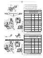
5. GAS PRESSURE
Whenahigherthanthemaximumrecommended
gas pressure is being maintained at the main gas line,
*High Intensity Heaters are only sold as 4040, 8060, 9100S, and 9120
**Differentmodelnumbersareachievedbyusingsupplementaloricesincludedwithheaterstochangeheatoutput.

4
Enerco Group, Inc. |Gas-Fired Infra-Red Space Heaters OperatingInstructionsandOwner’sManual
a separate regulator must be installed ahead of the
heater.RefertoFigure2formaximumallowablepres-
sure for stated model and gas.
See heater rating plate for minimum gas supply pres-
sure “For the Purpose of Input Adjustment”
On a multiple heater installation it may be possible to
use one large capacity regulator or an individual regula-
tor for each heater. Nevertheless, it is recommended
practice to make the entire pipe system a loop. Contact
your local representative or the factory for proper gas
pressure reducing design stage.
WARNING: DO NOT EXCEED ½ P.S.I. INLET PRES-
SURE TO HEATERS SHOWN IN FIGURES 1 AND 2
6. ELECTRICAL
Allexternalwiringmustbeinaccordancewiththe
existingelectricalcode.Usewiringdiagramfurnished
with heater. Be sure electric supply characteristics
match those called for on the name plate. The unit
must be electrically grounded in accordance with the
National Electrical Code, ANSI/NFPA70, latest revision.
In Canada refer to Canadian electrical code CSA C22.1
7. THERMOSTAT & LOCATION
Make sure that the electrical characteristics of the
thermostat match those of the heater controls. For best
results thermostat should be positioned 5 ft. above
floor where air can circulate freely around it. DO NOT
MOUNT directly to cold-side wall, in direct drafts or
directly beneath the infra-red heater.
8. VENTILATION
a.Theminimumintakeandexhaustairopeningsshallpro-
vide for not less than 400 CFM for every 100,000 BTU
inputexceptthattheinltrationareamaybeincluded
intheintakearea.Theexhaustfanmustbeinterlocked
withtheheaterthermostat.Ifapowerexhaustfan
is used, it should be controlled by the thermostat or
humidistat
b.Wherenatural(gravity)ventilationisprovidedfor
exhaust,theopeningsmustbedistributedabovethe
heaters(preferablyatthepeakoftheroof)andthe
areas of openings shall not be less than 300 square
inches for every 100,000 BTU input.
9. OPERATIONS
Upon completion of electrical wiring, gas piping and
purging of gas lines to heaters, refer to the lighting
instruction plate attached to heater for proper lighting
procedure.
10. CLEANING INFORMATION
Blow out Venturi and burner face with compressed
air(25#max.pressure);alsocleanorices(seeFigure
2forcorrectsizedrill).Fordetailedmaintenanceand
cleaning instructions contact your local representative
or factory.
WARNING: GASKET BINDER MATERIAL USED
IN THIS HEATER ASSEMBLY WILL TEMPORARILY EMIT
ANODORAND/ORVAPOR.USEVENTILATION(aOR
b)ANDTHISCONDITIONWILLCLEARUPINAPPROXI-
MATELY 20 MINUTES AND WILL NOT REOCCUR.
WARNING: DO NOT ATTEMPT TO IGNITE THE
PILOT BY HAND ON HEATERS EQUIPPED WITH AUTO-
MATIC SPARK IGNITION.
WARNING: THE STATE OF CALIFORNIA REQUIRES
THE FOLLOWING WARNING: COMBUSTION BY-PROD-
UCTS PRODUCED WHEN USING THIS PRODUCT CON-
TAIN CARBON MONOXIDE, A CHEMICAL KNOWN TO
THE STATE OF CALIFORNIA TO CAUSE CANCER AND
BIRTHDEFECTS(OROTHERREPRODUCTIVEHARM).
NOTE: USE LATEST EDITION FOR ALL ANSI STAN-
DARD AND CANADIAN STANDARDS.
FIGURE 2
MODEL
NO.
BTU/HR. RATING GASSUPPLYPRESSURE(W.C.)
ORIFICE SIZE
GAS MIN. MAX. MANIFOLD
NATURAL PROPANE NAT. L.P. NAT. L.P. NAT. L.P. NAT. L.P.
4030 30,000 30,000 6.6” 11” 14” 14” 5.6” 10” 43 52
4040 40,000 40,000 6.8” 11” 14” 14” 5.8” 10” 37 49
8050 50,000 50,000 7.0” 11” 14” 14” 4.3” 10” 30 45
8060 60,000 60,000 7.0” 11” 14” 14” 5.8” 10” 29 43
8070 70,000 – 7.0” – 14” – 6.0” – 28 –
9080 80,000 80,000 7.0” 11” 14” 14” 5.8” 10” 37 49
9090 90,000 90,000 7.0” 11” 14” 14” 5.0” 10” 32 47
9100S 100,000 100,000 7.0” 11” 14” 14” 5.0” 10” 31 46
9100 100,000 100,000 7.0” 11” 14” 14” 4.3” 10” 30 45
9120 120,000 120,000 7.0” 11” 14” 14” 5.8” 10” 29 43
9140 140,000 – 7.0” – 14” – 5.5” – 28 –

5
OperatingInstructionsandOwner’sManualEnerco Group, Inc. | Gas-Fired Infra-Red Space Heaters
CONNECTION DIAGRAM FOR FLAME ROD CURRENT
FOR FLAME RECTIFICATION SYSTEMS (DSP-5, A5)
MEANS OF PROVING ADEQUATE GROUNDING AREA
The proper flame-rod-to-ground-area ratio cannot
alwaysbedeterminedbyvisualexaminationorphysical
measurement. A positive means of checking the instal-
lation is the measurement of the flame rod current
underactualringconditions.Itisdenitelyrecom-
mended that the installer measure the current flow be-
tween the lead of the flame rod unit and the terminal
inthecontrolterminalboard(seeFigure3).Measure
the current with a DC Microammeter or equal. We
recommend a steady output of .9 microamperes or
more. A steady flow of current in this amount under
actualringconditionswillgenerallyindicateadequate
grounding of the pilot flame.
NOTE:
1. Read all control data sheet supplied with this heater.
2. Check flame rod for any contact to heater parts. Flame
rod must be free of any contact to heater. Contact with
heater will short circuit flame rod.
3. Cracked porcelain on flame rod will short circuit sensor.
Replace flame rod.
Figure 3 – Using a microammeter to prove adequate grounding area.
Gas
Flame
Flame
Rod
Flame
Rod Assy.
Microammeter
Control
Terminal For
Flame Rod
Loadwire
G
THERMOSTAT
Thermostat
Powerpile Thermocouple
Honeywell Q313A
Factory wired
Powerpile Gas Valve – Honeywell VS820
WIRE
SIZES
MAXIMUM
LENGTH
OF WIRE
CABLE
NO 18 15 FEET
NO 16 30 FEET
NO 14 50 FEET
CAUTION TO INSTALLER
NEVER CONNECT POWERPILE
GAS VALVE OR THERMOSTAT
TO LINE VOLTAGE OR A
TRANSFORMER.
NOTE Donotexceedthe
maximumlengthslistedinthe
table when wiring between the
Thermostat and Gas Valve with
cable not supplied by HEAT STAR.
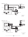
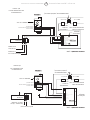
CONNECTION DIAGRAM

6
Enerco Group, Inc. |Gas-Fired Infra-Red Space Heaters OperatingInstructionsandOwner’sManual
SP715A
IGN
SP745
PV
GND
TR
PV/MV
TH
MV
LOGIC BOX
THERMOSTAT NOT
BY HEAT STAR
120 VAC
24 VOLT
THERMOSTAT
OPTIONAL
24 VAC
TRANSFORMER(SHIPPEDLOOSE)
COMBINED LOAD: 1.5 AMP.
PILOT BURNER
SPARK ELECTRODE /
FLAME SENSOR
MAIN BURNER
PV
PV/MV
MV
GAS VALVE
VR8204
A5 CONNECTION
DIAGRAM
REF. B2984-1
TH
PV
SENSE
EJ
MV
MV/PV
TR
GND
IGN
LOGIC BOX
THERMOSTAT NOT
BY HEAT STAR
120 VAC
24 VOLT
THERMOSTAT
OPTIONAL
24 VAC
TRANSFORMER(SHIPPEDLOOSE)
COMBINED LOAD: 1.5 AMP
PILOT BURNER
SPARK ELECTRODE
FLAME SENSOR
MAIN BURNER
PV
PV/MV
MV
GAS VALVE
VR8204
NDSP-5 CONNECTION
DIAGRAM
REF. A2983-1

7
OperatingInstructionsandOwner’sManualEnerco Group, Inc. | Gas-Fired Infra-Red Space Heaters
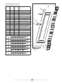
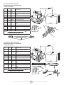
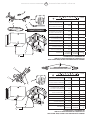
Replacement Parts List For Heaters
4000 Series Models / Less Control
Item
No.
No.
Req’d.
Stock
No.
Description
1 1 00435 A Reflector Assembly
2 1 02523 A Burner Assembly
3 1 03397 P Venturi
4
5 1 05437 Orice–Br.N.G.4040
6 1 05443 Orice–Br.N.G.4030
7 1 05449 Orice–Br.L.P.4040
8 1 05452 Orice–Br.L.P.4030
9 1 12366 Gasket – Venturi
10
11
1 3 5 9
4040 Nat. Gas
2
or
1 3 6 9
4040 Nat. Gas
2
or
1 3 7 9
4040 Propane
2
or
1 3 8 9
4040 Propane
2
or
Replacement Parts List For Heaters
8000 Series Models / Less Control
Item
No.
No.
Req’d.
Stock No. Description
1 1 00442 A Reflector Assembly
2 1 02524 A Burner Assembly
3 1 03421 P Venturi
4
5 1 05428 Orice–Br.N.G.8070
6 1 05429 Orice–Br.N.G.8060
7 1 05430 Orice–Br.N.G.8050
8 1 05443 Orice–Br.L.P.8060
9 1 05445 Orice–Br.L.P.8050
10 1 12366 Gasket – Venturi
11
12
1 3 5 10
8070 Nat. Gas
2
or
1 3 6 10
8060 Nat. Gas
2
or
1 3 7 10
8050 Nat. Gas
2
or
1 3 8 10
8060 Propane
2
or
1 3 9 10
8050 Propane
2
or
5
6
7
8
1 2
9
3
5
6
7
8 9
1 2
10
3

8
Enerco Group, Inc. |Gas-Fired Infra-Red Space Heaters OperatingInstructionsandOwner’sManual
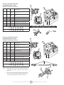
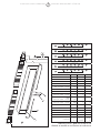
Replacement Parts List For Heaters
9000 Series Models / Less Control
Item
No.
No.
Req’d.
Stock No. Description
1 1 00444 A Reflector Assembly
2 2 02694 Burner Assembly
3 2 03421 P Venturi
4
5
6 2 05428 Orice–Br.N.G.9140
7 2 05429 Orice–Br.N.G.9120
8 2 05430 Orice–Br.N.G.9100
9 2 05443 Orice–Br.L.P.9120
10 2 05445 Orice–Br.L.P.9100
11 2 06396 Manifold Assembly
12 2 12366 Gasket – Venturi
13
14 1 14639 Center Saddle Bracket
15 1 11 3 81 CenterSupportAss’y
16
17
9140 Nat. Gas
1 3
12
6
1411 15
2
or
9120 Nat. Gas
1 3
12
7
1411 15
2
or
9100 Nat. Gas
1 3
12
8
1411 15
2
or
9120 Propane
1 3
12
9
1411 15
2
or
9100 Propane
1 3
12
10
1411 15
2
or
1
11
15
14
7
8
9 10
12
6
3
2

9
OperatingInstructionsandOwner’sManualEnerco Group, Inc. | Gas-Fired Infra-Red Space Heaters
Replacement Parts List For Heaters
9100S Series Models / Less Control
Item No.
No.
Req’d.
Stock No. Description
1 1 00443 A Reflector Assembly
2 2 02508 A Burner Assembly
3 2 03421 P Venturi
4
5
6 2 05431 Orice–Br.N.G.9100S
7 2 05432 Orice–Br.N.G.9090
8 2 05437 Orice–Br.N.G.9080
9 2 05446 Orice–Br.L.P.9100S
10 2 05447 Orice–Br.L.P.9090
11 2 05449 Orice–Br.L.P.9080
12 2 06398 Manifold Assembly
13 2 12366 Gasket – Venturi
14
15 1 14639 Center Saddle Bracket
16 1 11 3 81 Center Support Assembly
9100S Nat. Gas
1 3
13
6
1512 16
2
or
9090 Nat. Gas
1 3
13
7
1512 16
2
or
9080 Nat. Gas
1 3
13
8
1512 16
2
or
9100S Propane
1 3
13
9
1512 16
2
or
9090 Propane
1 3
13
10
1512 16
2
or
9080 Propane
1 3
13
11
1512 16
2
or
15
12
1
6 7
8 9
10 11
2
16
3
13

10
Enerco Group, Inc. |Gas-Fired Infra-Red Space Heaters OperatingInstructionsandOwner’sManual
1
3
2
5
1
3
2
or
4
8
6
7
10
9
9
5
4
8
6
7
10
FOR HEAT STAR SERIES 4000, 8000
REPLACEMENT PARTS LIST FOR CONTROL
SYSTEM SUFFIX NDSP-5
ITEM
NO.
NO.
REQ’D
STOCK
NO.
DESCRIPTION
1 1 00028 IGNITIONCONTROL#SP715A
2 1 00037 GAS VALVE DSP-5/VR8204A2001/
SWC
3 1 00228 CONTROL ASSY. NDSP-5
4 1 05573 ORIFICE PILOT NG.
5 1 08353 TRANSFORMER 40VA
6 1 09374 PROBE T/C 1 5/32” LONG
7 1 09375 PROBE LEAD 4000, 8000, 9000
HTRS.
8 1 11403 PILOT BURNER ASSY.
9 1 14606 BRACKET MTG. SP715A RS.L. &
HON.V.
10 1 16425 FLEX PILOT TUBE W/FITTINGS
NDSP-5
2
or
1 2 4 5 6 7 8 9 10
FOR HEAT STAR SERIES 9000, 9000S
REPLACEMENT PARTS LIST FOR CONTROL
SYSTEM SUFFIX NDSP-5
ITEM
NO.
NO.
REQ’D
STOCK
NO.
DESCRIPTION
1 1 00028 IGNITIONCONTROL#SP715A
2 1 00037
GAS VALVE DSP-5/VR8204A2001/
SWC
3 1 00228 CONTROL ASSY. NDSP-5
4 1 05383 ORIFICE PILOT – NG
5 1 08353 TRANSFORMER 40VA
6 1 09374 PROBE T/C 1 5/32” LONG
7 1 09375
PROBE LEAD 4000, 8000, 9000
HTRS.
8 1 113 85 PILOT BURNER ASSY.
9 1 14606
BRACKET MTG. SP715A RS.L. &
HON.V.
10 1 16425 FLEX PILOT TUBE W/FITTINGS
NDSP-5
2
or
1 2 4 5 6 7 8 9 10

11
OperatingInstructionsandOwner’sManualEnerco Group, Inc. | Gas-Fired Infra-Red Space Heaters
FOR HEAT STAR SERIES 9000, 9000S
REPLACEMENT PARTS LIST FOR CONTROL
SYSTEM SUFFIX LA5
ITEM
NO.
NO.
REQ’D
STOCK
NO.
DESCRIPTION
1 1 00036
GAS VALVE A5/VR8204A2092/11”
WC
2 1 00039
CONTROL LOGIC /A5/
#SP745NL36005
3 1 00329 CONTROL ASSY. LA5
4 1 05384 ORIFICE PILOT – LP
5 1 08353 TRANSFORMER 40VA
6 1 11 3 8 5 PILOT BURNER ASSY.
7 1 14615
BRACKET MTG. A5, 745RS.L. &
HON.V.
8 1 16425 FLEX PILOT TUBE W/FITTINGS
LA5
3
or
1 2 4 5 6 7 8
FOR HEAT STAR SERIES 4000, 8000
REPLACEMENT PARTS LIST FOR CONTROL
SYSTEM SUFFIX LA5
ITEM
NO.
NO.
REQ’D
STOCK
NO.
DESCRIPTION
1 1 00036
GAS VALVE A5/VR8204A2092/11”
WC
2 1 00039
CONTROL LOGIC /A5/
#SP745NL36005
3 1 00329 CONTROL ASSY. LA5
4 1 05577 ORIFICE PILOT – LP
5 1 08353 TRANSFORMER 40VA
6 1 11407 PILOT BURNER ASSY.
7 1 14615
BRACKET MTG. A5, 745RS.L. &
HON.V.
8 1 16425 FLEX PILOT TUBE W/FITTINGS
LA5
3
or
1 2 4 5 6 7 8
1 2
3
7
4
8
5
6
8
5
6
1
2
3
7
4

12
Enerco Group, Inc. |Gas-Fired Infra-Red Space Heaters OperatingInstructionsandOwner’sManual
FOR HEAT STAR SERIES 9000, 9000S
REPLACEMENT PARTS LIST FOR
CONTROL SYSTEM SUFFIX NPP, LPP
ITEM
NO.
NO.
REQ’D
STOCK
NO.
DESCRIPTION
1 1 00024
COMB.GASVALVE(PP)NG.
1/2x1/2NPT
2 1 00025
COMB.GASVALVE(PP)LP.1/2x1/2
NPT
3 1 05384 ORIFICE PILOT LP
4 1 05383 ORIFICE PILOT NG
5 1 09360 THERMOCOUPLE PP HONEYWELL
6 1 10367 THERMOSTAT “PP” HEAT STAR
7 1 11 3 8 5 PILOT BURNER-9000HTR
8 1 16425 FLEX PILOT TUBE WITH FITTINGS
NPP
1 4 5 6 7 8
LPP
2 3 5 6 7 8
FOR HEAT STAR SERIES 4000, 8000
REPLACEMENT PARTS LIST FOR
CONTROL SYSTEM SUFFIX NPP, LPP
ITEM
NO.
NO.
REQ’D
STOCK
NO.
DESCRIPTION
1 1 00024
COMB.GASVALVE(PP)NG.
1/2x1/2NPT
2 1 00025
COMB.GASVALVE(PP)LP.1/2x1/2
NPT
3 1 05577 ORIFICE PILOT LP
4 1 05573 ORIFICE PILOT NG
5 1 09360 THERMOCOUPLE PP HONEYWELL
6 1 10367 THERMOSTAT “PP” HEAT STAR
7 1 11405 PILOT-PP-4K, 8K HTR NG
7 1 11408 PILOT-PP-4K, 8K HTR LP
8 1 16425 FLEX PILOT TUBE WITH FITTINGS
NPP
1 4 5 6 7 8
LPP
2 3 5 6 7 8
NOTE: 1 – WHEN ORDERING SPARE PARTS ALWAYS GIVE HEATER
MODEL NO., STOCK NO., SERIAL NO., AND TYPE OR
GAS USED.
2 – WHEN DISASSEMBLING PARTS FROM HEATER FOR RE-
PAIR, CAREFULLY NOTE ORIENTATION OF PARTS, AND
THEN REVERSE PROCEDURE WHEN ASSEMBLING.
1
4
5
6
7
8
2
3
1
5
3
6
2
8
4
5
7

13
OperatingInstructionsandOwner’sManualEnerco Group, Inc. | Gas-Fired Infra-Red Space Heaters
SUGGESTED HANGING METHOD
MODEL: 4000, 8000, 9000, MH40
TYPICAL BEAM MOUNT
FIGURE 4
CEILING
SIDE
WALL
FLOOR
HORIZONTAL MOUNT
BACK
SEE INSTALLATION INSTRUCTIONS FOR
DETAILED CLEARANCES INFORMATION
CLEARANCES TO COMBUSTIBLES
BELOW
TOP
BEAM CLAMP
THREADED ROD
WHEN ANGLE MOUNTING
ELEVATE ONLY DESIGNATED
SIDE OF HEATER
FIGURE 5
ANGLE IRON
SEE CHAIN KIT
#17374OR
THREADED ROD
FROM
HORIZONTAL
MAXIMUM
45°
TYPICAL WALL MOUNT
HEATER SIDE REFLECTOR MUST
BE PARALLEL TO THE FLOOR
MOUNTING
SEE CHAIN
KIT#17374
OR THREAD-
ED ROD
F114581 HANGING
BRACKET KIT
F114581 HANGING
BRACKET KIT
OR CHAIN
KIT 17374
RECOMMEND USING
HEATER HANGING
BRACKET F114581

14
Enerco Group, Inc. |Gas-Fired Infra-Red Space Heaters OperatingInstructionsandOwner’sManual
FIGURE 6
LOW PRESSURE, MAIN GAS LINE
SEE FIGURE 2 FOR PROPER INLET PRESSURES
FOR HIGHER PRESSURES THAN SHOWN ABOVE
CONTACT FACTORY FOR PROPER REGULATOR
ON THREADED PIPES USE A PIPE COMPOUND WHICH
IS RESISTANT TO THE ACTION OF ALL GASES
MUST BE RESISTANT TO PROPANE
TYPICAL LOW PRESSURE
STANDARD INSTALLATION
HEATER
MOUNTING HOLES-4 REQ’D
SIDE VIEW
½ PSI MAX.
SHUT-OFF VALVE
TEE
DRIP LEG
CAP
HIGH ALTITUDE OPERATION
Please contact the factory for a detailed High Altitude 1.
ConversionKittosuityourspecicneed.
1.1 Be prepared to answer factory questions regard-
ing: Type of fuel for the proposed appliance con-
version,gaspressureavailableatsite,andspecic
altitude at site.
“The conversion shall be carried out by a manufac-2.
turer’sauthorizedrepresentative,inaccordancewith
the requirements of the manufacturer, provincial or
territorial authorities having jurisdiction and in accor-
dance with their requirements.”
High Altitude Conversion Kits will include high 3.
altitude rating plate with stamped data, necessary
oricesorburnerasrequiredforspecicneedand
additional installation instructions.
In Canada, Heater installations at High Altitudes shall 4.
comply with the applicable construction provisions of
thecurrentstandardCAN1-2.17,gasredappliances
for use at high altitudes.
RIGID OR FLEXIBLE GAS
LINE TO HEATER
PIPE NIPPLE

15
OperatingInstructionsandOwner’sManualEnerco Group, Inc. | Gas-Fired Infra-Red Space Heaters
THIS PAGE INTENTIONALLY
LEFT BLANK

16
Enerco Group, Inc. |Gas-Fired Infra-Red Space Heaters OperatingInstructionsandOwner’sManual
WARNING: USEONLYMANUFACTURER’SREPLACEMENTPARTS.USE
OF ANY OTHER PARTS COULD CAUSE INJURY OR DEATH. REPLACEMENT PARTS
ARE ONLY AVAILABLE DIRECT FROM THE FACTORY AND MUST BE INSTALLED BY
A QUALIFIED SERVICE AGENCY.
PARTS ORDERING INFORMATION:
PURCHASING: Accessories may be purchased at any Mr. Heater/HeatStar local dealer
or direct from the factory
FOR INFORMATION REGARDING SERVICE
PleasecallToll-Free800-251-0001•www.enerco-mrheater.com
Ourofcehoursare8:30AM–5:00PM,EST,MondaythroughFriday.
Email to: techservice@enerco-mrheater.com
Please include the model number, date of purchase, and description of problem in all
communication.
LIMITED WARRANTY
The company warrants this product to be free from imperfections in material or workmanship,
under normal and proper use in accordance with instructions of The Company, for a period of
one year from the date of delivery to the buyer. The Company, at its option, will repair or replace
products returned by the buyer to the factory, transportation prepaid within said one year period
and found by the Company to have imperfections in material or workmanship.
Pro-rated 10-year warranty on the burner assembly only.
If a part is damaged or missing, call our Technical Support Department at 800-251-0001.
Address any Warranty Claims to the Service Department, Enerco Group, Inc., 4560 W. 160th St.,
Cleveland, Ohio 44135. Include your name, address and telephone number and include details
concerning the claim. Also, supply us with the purchase date and the name and address of the
dealer from whom you purchased our product.
TheforegoingisthefullextentoftheresponsibilityoftheCompany.Therearenoother
warranties,expressorimplied.Specicallythereisnowarrantyoftnessforaparticularpurpose
and there is no warranty of merchantability. In no event shall the Company be liable for delay
causedbyimperfections,forconsequentialdamages,orforanychargesoftheexpenseof
any nature incurred without its written consent. The cost of repair or replacement shall be the
exclusiveremedyforanybreachofwarranty.Thereisnowarrantyagainstinfringementofthe
like and no implied warranty arising from course of dealing or usage of trade. This warranty will
not apply to any product which has been repaired or altered outside of the factory in any respect
which in our judgment affects its condition or operation.
Somestatesdonotallowtheexclusionorlimitationofincidentalorconsequentialdamages,so
theabovelimitationorexclusionmaynotapplytoyou.ThisWarrantygivesyouspeciclegal
rights, and you may have other rights which vary from state to state.
Enerco Group, Inc.,
reserves the right to make changes at any time, without notice or
obligation,incolors,specications,accessories,materialsandmodels.
ENERCOGROUP,INC.,4560W.160THST.,CLEVELAND,OHIO44135•216-881-5500
Mr. Heater is a registered trademarks of Enerco Group, Inc.
© 2008, Enerco Group, Inc. All rights reserved
ANSI Z83.19b-2008/CSA 2.35-2007
®
®
18650 Rev. A 06/08
OPERATING INSTRUCTIONS AND OWNER’S MANUAL
READ INSTRUCTIONS CAREFULLY: Read and follow all
instructions. Place instructions in a safe place for future
reference. Do not allow anyone who has not read these
instructions to assemble, light, adjust or operate the heater.
HEATSTAR High-Intensity Infrared Heaters
HS4030 HS8070 HS9100
HS4040 HS9080 HS9120
HS8050 HS9090 HS9140
HS8060 HS9100S
MODELS
Page is loading ...

15
Guide d'utilisation et instructions de fonctionnementEnerco Group, Inc. | Appareils de chauffage à gaz infrarouge
CETTE PAGE EST LAISSÉE
BLANCHE INTENTIONNELLEMENT

14
Enerco Group, Inc. | Appareils de chauffage à gaz infrarouge Guide d'utilisation et instructions de fonctionnement
FIGURE 6
CONDUITE DE GAZ PRINCIPALE, BASSE PRESSION
CONSULTEZLAFIGURE2POURCONNAÎTRELESPRESSIONSD'ENTRÉEADÉQUATES
ENCASDEPRESSIONSUPÉRIEUREÀLAVALEURINDIQUÉECI-DESSUS,
COMMUNIQUEZ AVEC LE FABRICANT POUR OBTENIR LE RÉGULATEUR APPROPRIÉ
SUR LES CONDUITES FILETÉES, UTILISEZ UN COMPOSÉ À
CONDUITE RÉSISTANT À L'ACTION DE TOUS LES GAZ
DOIT ÊTRE RÉSISTANT AU PROPANE
INSTALLATION
STANDARD BASSE PRESSION
APPAREIL DE CHAUFFAGE
TROUSDEFIXATION-QUANTITÉ4
VUE DE CÔTÉ
½ PSI MAX.
ROBINET D'ARRÊT
TÉ
COLLECTEUR DE CONDENSATS
CAPUCHON
UTILISATION À HAUTE ALTITUDE
Veuillez communiquer avec le fabricant pour obtenir 1.
des renseignements détaillés sur l'ensemble de
conversion haute altitude qui convient précisément
à vos besoins.
1.1 Soyez prêt à répondre aux questions du fabricant
concernant le type de combustible utilisé avec
l'appareil converti, la pression de gaz dont on dispose
sur les lieux et l'altitude des lieux.
«Laconversiondoitêtreeffectuéeparun2.
représentant autorisé du fabricant, conformément
aux exigences du fabricant ainsi que des autorités
provincialesouterritorialesayantjuridiction.»
Les ensembles de conversion haute altitude 3.
comprennent une plaque signalétique haute altitude
portantdesdonnéesestampillées,lesajutagesoule
brûleur nécessaires selon les besoins, ainsi que des
instructions d'installation supplémentaires.
Au Canada, les installations d'appareils de chauffage 4.
à haute altitude doivent être conformes aux
dispositions pertinentes concernant la construction
qui sont données par la version en vigueur de la
normeCAN1-2.17surlesappareilsàgazpour
utilisation à haute altitude.
CONDUITE DE GAZ
RIGIDE OU FLEXIBLE
VERS L'APPAREIL DE
CHAUFFAGE
RACCORD DE
CONDUITE

13
Guide d'utilisation et instructions de fonctionnementEnerco Group, Inc. | Appareils de chauffage à gaz infrarouge
MÉTHODE DE SUSPENSION SUGGÉRÉE
MODÈLE : 4000, 8000, 9000, MH40
FIXATION TYPE À UNE POUTRE
FIGURE 4
PLAFOND
CÔTÉ
MUR
PLANCHER
FIXATION HORIZONTALE
ARRIÈRE
CONSULTEZ LES INSTRUCTIONS D'INSTALLATION POUR OBTENIR
DES RENSEIGNEMENTS DÉTAILLÉS SUR LES DISTANCES DE SÉCURITÉ
DISTANCES DES MATÉRIAUX COMBUSTIBLES
DESSOUS
DESSUS
COLLIER DE
POUTRE
TIGE FILETÉE
LORS D'UNE FIXATION EN ANGLE,
ÉLEVEZ SEULEMENT LE CÔTÉ DÉSI-
GNÉ DE L'APPAREIL DE CHAUFFAGE
FIGURE 5
CORNIÈRE
VOIR L'ENSEM-
BLEDECHAÎNE
Nº 17374 OU LA
TIGE FILETÉE
DEPUIS LE
MAXIMUM
HORIZONTAL
45 °
FIXATION MURALE TYPE
LE RÉFLECTEUR DU CÔTÉ APPAREIL
DE CHAUFFAGE DOIT ÊTRE
PARALLÈLE AU PLANCHER
FIXATION
VOIR L'ENSEMBLE
DECHAÎNE
Nº 17374
OU TIGE
FILETÉE
F114581 ENSEMBLE DE
FERRURE DE SUSPENSION
F114581 ENSEMBLE
DE FERRURE DE
SUSPENSION
OU ENSEMBLE
DECHAÎNE
17374
IL EST RECOMMAN-
DÉ D'UTILISER LA
FERRURE DE SUSPEN-
SION D'APPAREIL DE
CHAUFFAGE F114581

12
Enerco Group, Inc. | Appareils de chauffage à gaz infrarouge Guide d'utilisation et instructions de fonctionnement
APPAREILS DE CHAUFFAGE HEAT STAR DE SÉRIES 9000 ET 9000S
LISTE DE PIÈCES DE RECHANGE POUR LE SYSTÈME
DE COMMANDE À SUFFIXE NPP OU LPP
N°
D'ARTICLE
QUANTITÉ
NÉCESSAIRE
NUMÉRO DE
RÉFÉRENCE
DESCRIPTION
1 1 00024
ROBINETDEGAZCOMBINÉ(PP)
GAZ NATUREL 1/2 x 1/2 NPT
2 1 00025
ROBINET DE GAZ COMBINÉ
(PP)GAZDEPÉTROLELIQUÉFIÉ
1/2 x 1/2 NPT
3 1 05384
AJUTAGEVEILLEUSEGAZDE
PÉTROLE LIQUÉFIÉ
4 1 05383
AJUTAGEVEILLEUSEGAZ
NATUREL
5 1 09360
THERMOCOUPLE PP
HONEYWELL
6 1 10367 THERMOSTAT«PP»HEATSTAR
7 1 11 3 8 5
BRÛLEURVEILLEUSE-APPAREIL
DE CHAUFFAGE 9000
8 1 16425
TUBE FLEXIBLE DE VEILLEUSE
AVEC RACCORDS
NPP
LPP
APPAREILS DE CHAUFFAGE HEAT STAR DE SÉRIES 4000 ET 8000
LISTE DE PIÈCES DE RECHANGE POUR LE SYSTÈME
DE COMMANDE À SUFFIXE NPP OU LPP
N°
D'ARTICLE
QUANTITÉ
NÉCESSAIRE
NUMÉRO DE
RÉFÉRENCE
DESCRIPTION
1 1 00024
ROBINETDEGAZCOMBINÉ(PP)
GAZ NATUREL 1/2 x 1/2 NPT
2 1 00025
ROBINET DE GAZ COMBINÉ
(PP)GAZDEPÉTROLELIQUÉFIÉ
1/2 x 1/2 NPT
3 1 05577
AJUTAGEVEILLEUSEGAZDE
PÉTROLE LIQUÉFIÉ
4 1 05573
AJUTAGEVEILLEUSEGAZ
NATUREL
5 1 09360
THERMOCOUPLE PP
HONEYWELL
6 1 10367 THERMOSTAT«PP»HEATSTAR
7 1 11405
VEILLEUSEPP-APPAREILSDE
CHAUFFAGE 4000 ET 8000 GAZ
NATUREL
7 1 11408
VEILLEUSEPP-APPAREILSDE
CHAUFFAGE 4000 ET 8000 GAZ
DE PÉTROLE LIQUÉFIÉ
8 1 16425
TUBE FLEXIBLE DE VEILLEUSE
AVEC RACCORDS
NPP
LPP
REMARQUE : 1 – LORSQUE VOUS COMMANDEZ DES PIÈCES DE
RECHANGE,INDIQUEZTOUJOURSLENUMÉRODE
MODÈLE, LE NUMÉRO DE RÉFÉRENCE ET LE NUMÉRO DE
SÉRIE DE L'APPAREIL DE CHAUFFAGE, AINSI QUE LE TYPE
DE GAZ UTILISÉ.
2 – LORSQUE VOUS DÉMONTEZ DES PIÈCES DE L'APPAREIL
DE CHAUFFAGE EN VUE D'UNE RÉPARATION, NOTEZ
SOIGNEUSEMENT L'ORIENTATION DES PIÈCES, PUIS SUIVEZ
LA PROCÉDURE INVERSE POUR REFAIRE LE MONTAGE.
1
4
5
6
7
8
2
3
1
5
3
6
2
8
4
5
7
1 4 5 6 7 8
2 3 5 6 7 8
1 4 5 6 7 8
2 3 5 6 7 8
Page is loading ...
Page is loading ...
Page is loading ...
Page is loading ...
Page is loading ...
Page is loading ...
Page is loading ...
Page is loading ...
Page is loading ...
Page is loading ...
Page is loading ...
-
 1
1
-
 2
2
-
 3
3
-
 4
4
-
 5
5
-
 6
6
-
 7
7
-
 8
8
-
 9
9
-
 10
10
-
 11
11
-
 12
12
-
 13
13
-
 14
14
-
 15
15
-
 16
16
-
 17
17
-
 18
18
-
 19
19
-
 20
20
-
 21
21
-
 22
22
-
 23
23
-
 24
24
-
 25
25
-
 26
26
-
 27
27
-
 28
28
-
 29
29
-
 30
30
-
 31
31
-
 32
32


Enerco HS4040 User manual
- Category
- Space heaters
- Type
- User manual
Ask a question and I''ll find the answer in the document
Finding information in a document is now easier with AI
in other languages
- français: Enerco HS4040 Manuel utilisateur
Related papers
-
Enerco HS300ID User manual
-
-
-
-
-
-
-
-
-
Other documents
-
HeatStar MH40 LP Operating instructions
-
HeatStar MH18CH Owner's manual
-
Mr. Heater HS170NG Operating instructions
-
-
-
-
-
-
-
Sharper Image Golf Cart Heater Owner's manual