Cub Cadet 2000 Series User manual
- Category
- Lawnmowers
- Type
- User manual
This manual is also suitable for

SERIES 2000
OPERATOR’S MANUAL
IMPORTANT: READ SAFETY RULES AND INSTRUCTIONS CAREFULLY
CUB CADET LLC P.O. BOX 361131 CLEVELAND, OHIO 44136-0019 [www.cubcadet.com]
PRINTED IN U.S.A.
Warning:
This unit is equipped with an internal combustion engine and should not be used on or near any unimproved forest-
covered, brush-covered or grass-covered land unless the engine’s exhaust system is equipped with a spark arrester meeting
applicable local or state laws (if any). If a spark arrester is used, it should be maintained in effective working order by the operator.
In the State of California the above is required by law (Section 4442 of the California Public Resources Code). Other states may have
similar laws. Federal laws apply on federal lands. A spark arrester for the muffler is available through your nearest engine authorized
service dealer or contact the service department, P.O. Box 361131 Cleveland, Ohio 44136-0019.
FORM NO. 770-10170C
TRACTOR
Model Number
LT 2180
(11/03)

2
Briggs & Stratton Corporation (B&S), the California Air Resources Board (CARB)
and the United States Environmental Protection Agency (U.S. EPA)
Emission Control Systems Warranty Statement(Owner’s Defect Warranty Rights and Obligations)
EMISSION CONTROL WARRANTY COVERAGE IS APPLICABLE TO CERTIFIED ENGINES PURCHASED IN CALIFORNIA IN 1995 AND THERE-
AFTER, WHICH ARE USED IN CALIFORNIA, AND TO CERTIFIED MODEL YEAR 1997 AND LATER ENGINES WHICH ARE PURCHASED AND
USED ELSEWHERE IN THE UNITED STATES (AND AFTER JANUARY 1, 2001 IN CANADA).
California and United States Emission Control Defects Warranty Statement
The California Air Resources Board (CARB), the U.S. Environmental Protection Agency (EPA), and Briggs & Stratton are pleased to explain the Emission
Control Systems Warranty on your model year 2002 and later small off-road engine (SORE). In California, new small off-road engines must be designed,
built and equipped to meet the State’s stringent anti-smog standards. Elsewhere in the United States, new non-road, spark-ignition engines certified for
model year 1997 and later must meet similar strandards set forth by the U.S. EPA. B&S must warrant the emission control system on your engine for the
periods of time listed below, provided there has been no abuse, neglect or improper maintenance of your small off-road engine.
Your emission control system includes parts such as the carburetor, air cleaner, ignition system, muffler and catalytic converter. Also included may be
connectors and other emission related assemblies.
Where a warrantable condition exists, Briggs & Stratton will repair your small off-road engine at no cost to you, including diagnosis, parts and labor.
Briggs & Stratton Emission Control Defects Warranty Coverage
Small off-road engines are warranted relative to emission control parts defects for a period of two years, subject to provisions set forth below. If any
covered part on your engine is defective, the part will be repaired or replaced Briggs & Stratton.
Owner’s Warranty Responsibilities
As the small off-road engine owner, you are responsible for the performance of the required maintenance listed in the Operator’s Manual. Briggs & Strat-
ton recommends that you retain all your receipts covering maintenance on your small off-road engine, but Briggs & Stratton cannot deny warranty solely
for the lack of receipts or for your failure to ensure the performance of all scheduled maintenance.
As the small off-road engine owner, you should however be aware that Briggs & Stratton may deny you warranty coverage if your small off-road engine or
a part has failed due to abuse, neglect, improper maintenance or unapproved modifications.
You are responsible for presenting your small off-road engine to an authorized Briggs & Stratton service dealer as soon as a problem exists. The undis-
puted warranty repairs should be completed in a reasonable amount of time, not to exceed 30 days.
If you have any questions regarding your warranty rights and responsibilities, you should contact a B&S service representative at 1-414-259-5652.
The emission warranty is a defects warranty. Defects are judged on normal engine performance. The warranty is not related to an in-use emission test.
Briggs & Stratton Emission Control Defects Warranty Provisions
The following are specific provisions relative to your Emission Control Defects Warranty Coverage. It is in addition to the B&S engine warranty for non-
regulated engines.
1. Warranted Parts — Coverage under this warranty extends only to the parts listed below (the emission control systems parts) to the extent these
parts were present on the engine purchased.
a. Fuel Metering System
• Cold start enrichment system
• Carburetor and internal parts
•Fuel pump
b. Air Induction System
• Air cleaner
• Intake manifold
c. Ignition System
• Spark plug(s)
• Magneto ignition system
d. Catalyst System
• Catalytic converter
• Exhaust manifold
• Air injection system, Pulse valve
e. Miscellaneous Items
• Vacuum, temperature, position, time sensitive valves and switches
• Connectors and assemblies
2. Length of Coverage — Briggs & Stratton warrants to the initial owner and each subsequent purchaser that the Warranted Parts shall be free from
defects in materials and workmanship which caused the failure of the Warranted Parts for a period of two years from the date the engine is
delivered to a retail purchaser.
3. No Charge — Repair or replacement of any Warranted Part will be performed at no charge to the owner, including diagnostic labor which leads to
the determination that a Warranted Part is defective, if the diagnostic work is performed at an authorized Briggs & Stratton service dealer. For
emission warranty service contact your nearest authorized Briggs & Stratton service dealer as listed in the “Yellow Pages” under “Engines,
Gasoline,” “Gasoline Engines,” “Lawn Mowers,” or similar category.
4. Claims and Coverage Exclusions — Warranty claims shall be filed in accordance with the provisions of the B&S Engine Warranty Policy. Warranty
coverage shall be excluded for failures of Warranted Parts which are not original Briggs & Stratton parts or because of abuse, neglect or improper
maintenance as set forth in the B&S Engine Warranty Policy. Briggs & Stratton is not liable to cover failures of Warranted Parts caused by the use
of add-on, non-original, or modified parts.
5. Maintenance — Any Warranted Part which is not scheduled for replacement as required maintenance or which is scheduled only for regular
inspection to the effect of “repair or replace as necessary” shall be warranted as to defects for the warranty period. Any Warranted Part which is
scheduled for replacement as required maintenance shall be warranted as to defects only for the period of time up to the first scheduled
replacement for that part. Any replacement part that is equivalent in performance and durability may be used in the performance of any
maintenance or repairs. The owner is responsible for the performance of all required maintenance, as defined in the Operator’s Manual.
6. Consequential Coverage — Coverage hereunder shall extend to the failure of any engine components caused by the failure of any Warranted Part
still under warranty.

3
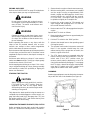
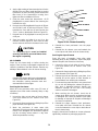
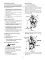
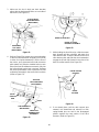
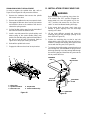
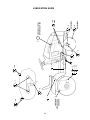
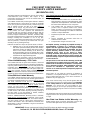
TRACTOR AND DECK PREPARATION
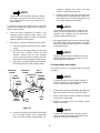
1. ATTACHING THE CHUTE DEFLECTOR
For shipping purposes, the mulching plug has been in-
stalled in the mower deck. The mulching plug must be
removed to install the chute deflector assembly.
WARNING
Do not operate the mower deck, even with the
mulching plug installed, unless the chute
defelector has been properly installed.
1. Remove the wing nut and carriage bolt securing the
mulching plug to the deck and withdraw the plug
from the discharge opening of the deck.
2. Remove the two hex nuts and bell washers from
the hex cap screws installed in the deck at the
chute opening.
3. Positon the deflector assembly to align the holes of
its hinge bracket with the two hex cap screws and
slide the hinge bracket onto the screws. Secure
with the two bell washers and hex nuts.
NOTE: The crowned (rounded) surface of the
washers go toward the hex nuts.
4. Refer to SECTION V-MOWER DECK when re-
installing the mulching plug.
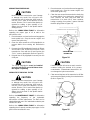
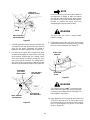
2. CONNECT THE BATTERY
WARNING
Battery posts, terminals and related accessories
contain lead and lead compounds. Wash hands
after handling.
The tractor is shipped with an activated sealed battery.
The positive battery cable is factory connected. The
negative cable must be connected.
Note: Make sure the ignition switch is in the "OFF" po-
sition before attaching the battery cables.
1. Pull the protective cap off the negative terminal of
the battery, and remove the hex cap screw and nut
from the free end of the negative battery cable.
2. Connect the negative battery cable (heavy black)
and ground wire (green) to negative terminal (—)
of the battery using the hex cap screw and nut.
3. Slide the black terninal cover over the negative
terminal of the battery.
WING NUT
HEX NUTS
BELL
WASHERS
CHUTE
DEFLECTOR
HEX CAP
SCREWS
MULCHING
PLUG
CARRIAGE
BOLT
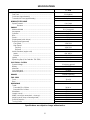
CONTENTS
Section Page
Emission Control Systems Warranty ... 2
Tractor and Deck Preparation.............. 3
Safe Operation Practices..................... 4
Product Graphics................................. 7
To The Owner...................................... 8
Calling Service Information.................. 8
Recording Model & Serial Number ...... 8
I Controls and Indicators........................ 9
II Operation............................................. 14
III Adjustments......................................... 18
IV Maintenance ........................................ 23
V Mower Deck......................................... 33
Section Page
VI Off-Season Storage............................. 45
VII Mowing................................................. 46
Optional Equipment and Accessories. 47
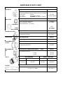
Maintenance Chart............................... 48
Trouble Shooting.................................. 49
Lubrication Table ................................. 51
Lubrication Guide................................. 52
Slope Gauge........................................ 55
Specifications....................................... 57
Warranty — Commercial Use ............. 58
Warranty — Residential Use ............... 59
Maintenance Parts Chart .................... 60

4
WARNING
• The engine exhaust, some of its constituents, and certain vehicle components contain or emit chemicals known
to the State of California to cause cancer, birth defects or other reproductive harm.
• This unit is equipped with an internal combustion engine and should not be used on or near any unimproved
forest-covered, brush-covered, or grass-covered land unless the engine’s exhaust system is equipped with a
spark arrester meeting applicable local or state laws (if any). If a spark arrester is used, it should be maintained
in effective working order by the operator.
• In the State of California, the above is required by law (Section 4442 of the California Public Resources Code).
Other States may have similar laws. Federal laws apply to federal lands. A spark arrester muffler is available
at your nearest engine authorized service center.
IMPORTANT
THIS SYMBOL POINTS OUT IMPORTANT SAFETY INSTRUCTIONS WHICH, IF NOT FOLLOWED,
COULD ENDANGER THE PERSONAL SAFETY AND/OR PROPERTY OF YOURSELF AND
OTHERS. READ AND FOLLOW ALL INSTRUCTIONS IN THIS MANUAL BEFORE ATTEMPTING
TO OPERATE YOUR UNIT. FAILURE TO COMPLY WITH THESE INSTRUCTIONS MAY RESULT
IN PERSONAL INJURY. WHEN YOU SEE THIS SYMBOL— HEED ITS WARNING.
SAFE OPERATION PRACTICES
Your lawn mower was built to be operated according to the rules for safe operation
in this manual. As with any type of power equipment, carelessness or error on the
part of the operator can result in injury. This lawn mower is capable of amputating
hands and feet or throwing objects. Failure to observe the following safety
instructions could result in serious injury or death.
I. GENERAL OPERATION
1. Read, understand and follow all instructions in the
manual and on the machine before starting. Keep
this manual in a safe place for future and regular
reference.
2. Only allow responsible individuals familiar with
the instructions to operate the machine. Know the
controls and how to stop the machine quickly.
3. Do not put hands or feet under the cutting deck or
near rotating parts.
4. Clear the area of objects such as rocks, toys,
wire, etc. which could be picked up and thrown by
the blades. A small object may have been
overlooked and could be accidentally thrown by
the mower in any direction and cause injury to
you or a bystander. To help avoid a thrown
objects injury, keep children, animals, bystanders
and helpers at least 75 feet from the mower while
it is in operation. Always wear safety glasses with
side shields or safety goggles during operation or
while performing an adjustment or repair, to
protect eyes from foreign objects. Stop the blades
when crossing gravel drives, walks or roads.
5. Be sure the area is clear of other people before
mowing. Stop machine if anyone enters the area.
6. Never carry passengers.
7. Disengage the blades before shifting into reverse
and backing up. Always look down and behind
before and while backing.
8. Be aware of the mower and attachment discharge
direction and do not point it at anyone. Do not
operate the mower without either the entire grass
catcher or the chute guard in place.
9. Slow down before turning. Operate the machine
smoothly. Avoid erratic operation and excessive
speed.
10. Never leave a running machine unattended.
Always turn off the blades, place the transmission
in neutral, set the parking brake, stop the engine
and remove key before dismounting.
11. Turn off blades when not mowing.
12. Stop the engine and wait until the blades come to
a complete stop before (a) removing the grass
catcher or unclogging chute, or (b) making any
repairs, adjusting or removing any grass or debris.
DANGER

5
13. Mow only in daylight or good artificial light.
14. Do not operate the machine while under the
influence of alcohol or drugs.
15. Watch for traffic when operating near or crossing
roadways.
16. Use extra care when loading or unloading the
machine into a trailer or truck. This unit should not
be driven up or down a ramp onto a trailer or truck
under power, because the unit could tip over
causing serious personal injury. The unit must be
pushed manually on a ramp to load or unload
properly.
17. Never make a cutting height adjustment while the
engine is running if the operator must dismount to
do so.
18. Wear sturdy, rough-soled work shoes and close-
fitting slacks and shirts. Do not wear loose fitting
clothes or jewelry. They can be caught in moving
parts. Never operate a unit in bare feet, sandals
or sneakers.
19. Check overhead clearance carefully before
driving under power lines, wires, bridges or low
hanging tree branches, before entering or leaving
buildings, or in any other situation where the
operator may be struck or pulled from the unit,
which could result in serious injury.
20. Disengage all attachment clutches, thoroughly
depress the brake pedal and shift into neutral
before attempting to start the engine.
21. Your mower is designed to cut normal residential
grass of a height no more than 10”. Do not
attempt to mow through unusually tall, dry grass
(e.g. pasture) or piles of dry leaves. Debris may
build up on the mower deck or contact the engine
exhaust presenting a potential fire hazard.
22. Use only accessories approved for this machine
by Cub Cadet. Read, understand and follow all
instructions provided with the approved
accessory.
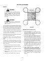
II. SLOPE OPERATION
Slopes are a major factor related to loss of control and
tip-over accidents, which can result in severe injury or
death. All slopes require extra caution. If you cannot
back up the slope or if you feel uneasy on it, do not
mow it.
For your safety, use the slope gauge included as part
of this manual to measure slopes before operating this
unit on a sloped or hilly area. If the slope is greater than
15° as shown on the slope gauge, do not operate this
unit on that area or serious injury could result.
DO:
Mow up and down slopes, not across.
Remove obstacles such as rocks, limbs, etc.
Watch for holes, ruts or bumps. Uneven terrain could
overturn the machine. Tall grass can hide obstacles.
Use slow speed. Choose a low enough gear so that
you will not have to stop or shift while on the slope. Al-
ways keep the machine in gear when going down
slopes to take advantage of engine braking action.
Follow the manufacturer’s recommendations for wheel
weights or counterweights to improve stability.
Use extra care with grass catchers or other attach-
ments. These can change the stability of the machine.
Keep all movement on the slopes slow and gradual.
Do not make sudden changes in speed or direction.
Rapid engagement or braking could cause the front of
the machine to lift and rapidly flip over backwards,
which could cause serious injury.
Avoid starting or stopping on a slope. If the tires lose
traction, disengage the blades and proceed slowly
straight down the slope.
DO NOT:
Do not turn on slopes unless necessary; then, turn
slowly and gradually downhill, if possible.
Do not mow near drop-offs, ditches or embankments.
The mower could suddenly turn over if a wheel is over
the edge of a cliff or ditch, or if an edge caves in.
Do not mow on wet grass. Reduced traction could
cause sliding.
Do not try to stabilize the machine by putting your foot
on the ground.
Do not use the grass catcher on steep slopes.
III. CHILDREN
Tragic accidents can occur if the operator is not alert
to the presence of children. Children are often
attracted to the machine and the mowing activity.
Never assume that children will remain where you
last saw them.
1. Keep children out of the mowing area and in
watchful care of an adult other than the operator.
2. Be alert and turn the machine off if children enter
the area.
3. Before and when backing up, look behind and
down for small children.
4. Never carry children, even with the blades off.
Children may fall off and be seriously injured or
may interfere with safe machine operation.

6
5. Never allow children under 14 years old to
operate the machine. Children 14 years and over
should only operate the machine under close
parental supervision and proper instruction.
6. Use extra care when approaching blind corners,
shrubs, trees or other objects that may obscure
your vision of a child or other hazard.
7. Remove the key when the machine is left
unattended to prevent unauthorized operation.
IV. SERVICE
1. Use extreme care in handling gasoline and other
fuels. They are extremely flammable and the
vapors are explosive.
a. Use only an approved container.
b. Never remove fuel cap or add fuel with the en-
gine running. Allow the engine to cool at least
two minutes before refueling.
c. Replace the fuel cap securely and wipe off any
spilled fuel before starting the engine as it may
cause a fire or explosion.
d. Extinguish all cigarettes, cigars, pipes and oth-
er sources of ignition.
e. Never refuel the machine indoors because fuel
vapors will accumulate in the area.
f. Never store the fuel container or machine
inside where there is an open flame or spark,
such as a gas hot water heater, space heater
or furnace.
2. Never run a machine inside a closed area.
3. To reduce fire hazard, keep the machine free of
grass, leaves or other debris build-up. Clean up
oil or fuel spillage. Allow the machine to cool at
least 5 minutes before storing.
4. Before cleaning, repairing or inspecting, make
certain the blade and all moving parts have
stopped. Disconnect the spark plug wire, and
keep the wire away from the spark plug to prevent
accidental starting.
5. Check the blade and engine mounting bolts at fre-
quent intervals for proper tightness. Also visually
inspect blades for damage (e.g., excessive wear,
bent, cracked). Replace with blades which meet
original equipment specifications.
6. Keep all nuts, bolts and screws tight to be sure
the equipment is in safe working condition.
7. Never tamper with safety devices. Check their
proper operation regularly. Use all guards as
instructed in this manual.
8. After striking a foreign object, stop the engine,
remove the wire from the spark plug and
thoroughly inspect the mower for any damage.
Repair the damage before restarting and
operating the mower.
9. Grass catcher components are subject to wear,
damage and deterioration, which could expose
moving parts or allow objects to be thrown. For
your safety protection, frequently check the
components and replace with manufacturer’s
recommended parts when necessary.
10. Mower blades are sharp and can cut. Wrap the
blades or wear gloves, and use extra caution
when servicing blades.
11. Check brake operation frequently. Adjust and
service as required.
12. Muffler, engine and belt guards become hot
during operation and can cause a burn. Allow to
cool down before touching.
13. Do not change the engine governor settings or
overspeed the engine. Excessive engine speeds
are dangerous.
14. Observe proper disposal laws and regulations.
Improper disposal of fluids and materials can
harm the environment and the ecology.
a. Prior to disposal, contact your local
Environmental Protection Agency to
determine the proper method for disposing of
the waste. Recycling centers are established
to properly dispose of materials in an
environmentally safe fashion.
b. Use proper containers when draining fluids.
Do not use food or beverage containers that
may mislead someone into drinking from
them. Properly dispose of the containers im-
mediately following the draining of fluids.
c. DO NOT pour oil or other fluids into the
ground, down a drain or into a stream, pond,
lake, or other body of water. Observe Environ-
mental Protection Agency regulations when
disposing of oil, fuel, coolant, brake fluid, fil-
ters, batteries, tires and other harmful waste.
15. We do not recommend the use of a pressure
washer or garden hose to clean your unit. They
may cause damage to electrical components;
spindles; pulleys; bearings; or the engine. The
use of water will result in shortened life and
reduce serviceability.
WARNING - YOUR RESPONSIBILITY: Restrict the use of this power machine to persons who
read, understand and follow the warnings and instructions in this manual and on the machine.

7
PRODUCT GRAPHICS
Keep product safety graphics (decals) clean. Replace
any safety graphic that is damaged, destroyed, miss-
ing, painted over or can no longer be read. Replace-
ment safety graphics are available through your
dealer.
GENERAL SAFETY INSTRUCTIONS
WARNING – LOCATED ON RIGHT
SIDE OF RUNNING BOARD
SAFETY GRAPHIC – LOCATED ON
LEFT SIDE OF MOWER DECK
HANDS AND FEET SAFETY GRAPHIC–
LOCATED ON DEFLECTOR CHUTE
DEFLECTOR and SAFETY GRAPHIC –
LOCATED ON RIGHT SIDE OF DECK
WARNING
!
BE FAMILIAR WITH CONTROLS BEFORE
STARTING ENGINE AND OPERATING.
SET CHOKE, MOVE THROTTLE TO MID
POSITION AND DEPRESS BRAKE PEDAL.
TURN KEY TO THE START POSITION.
AFTER ENGINE STARTS OPEN CHOKE.
STOPPING INSTRUCTIONS
DISENGAGE PTO AND SET PARKING BRAKE.
MOVE THROTTLE CONTROL TO MID
POSITION AND TURN KEY OFF.
STARTING INSTRUCTIONS
AVOID SERIOUS INJURY OR DEATH.
READ OPERATORS MANUAL AND ALL
WARNING LABELS BEFORE USING
MACHINE.
GO UP AND DOWN SLOPES, NOT ACROSS.
AVOID SUDDEN TURNS.
DO NOT OPERATE UNIT WHERE IT COULD
SLIP OR TIP.
IF MACHINE STOPS GOING UPHILL, STOP
PTO AND BACK DOWN HILL SLOWLY.
DO NOT MOW WHEN CHILDREN OR
OTHERS ARE AROUND.
NEVER CARRY CHILDREN.
LOOK DOWN AND BEHIND BEFORE AND
WHILE BACKING.
KEEP SAFETY DEVICES [GUARDS, SHIELDS,
AND SWITCHES] IN PLACE AND WORKING.
REMOVE OBJECTS THAT COULD BE
THROWN BY THE BLADES.
KNOW LOCATION AND FUNCTION OF ALL
CONTROLS.
BE SURE THE BLADES AND THE ENGINE
ARE STOPPED BEFORE PLACING HANDS
OR FEET NEAR BLADES.
BEFORE LEAVING OPERATOR'S
POSITION, DISENGAGE PTO, ENGAGE
BRAKE LOCK, SHUT OFF ENGINE AND
REMOVE KEY.
2.
3.
1.
2.
4.
1.
•
•
•
•
•
•
•
•
•
•
•
•
•
•
SAFETY GRAPHIC – LOCATED
ON LEFT SIDE OF DECK

8
TO THE OWNER
This Operator’s Manual is an important part of your new tractor. The information contained in this manual has been
prepared in detail to help you better understand the features, correct operation, adjustments, and maintenance of
your tractor. The performance and dependability of this tractor rely greatly on the manner in which it is operated and
maintained. Therefore, it is recommended that all operators of the tractor carefully read this manual and fully under-
stand its operation. Also keep the manual available for reference to ensure proper operation, and that maintenance
procedures are performed as scheduled to assure the tractor’s optimal mechanical condition.
NOTE: All references to LEFT, RIGHT, FRONT, and REAR, unless specifically stated otherwise, indicate that rela-
tive position on the tractor when facing forward while seated in the operator’s seat.
CAUTION: DO NOT tow your Model LT 2180 tractor. Towing may damage the transmission. Place the tractor on a
LEVEL SURFACE before pulling the transmission release lever to the disengaged position.
Your local authorized Cub Cadet dealer is interested in the performance you receive from your tractor, and with the
maintenance needed to ensure the satisfactory operation of your tractor. The dealer has trained service personnel
familiar with the latest servicing information, is equipped with the latest tools, and has a complete line of genuine
Cub Cadet service parts which assure proper fit and high quality.
CALLING SERVICE INFORMATION
The engine manufacturer is responsible for all engine-related issues with regards to performance, power-rating, and
specifications.
If you have difficulties with the tractor and/or equipment; have any questions regarding the operation or maintenance
of this equipment; or desire additional information not found in this manual, contact your nearest authorized Cub
Cadet dealer. If you need assistance in locating a dealer in your area, contact the Customer Dealer Referral Line by
calling:
1-877-282-8684
Or you may contact Cub Cadet via the internet by logging on to our Web Site at:
www.cubcadet.com
To obtain top performance and assure economical operation, the tractor should be inspected by your authorized
dealer periodically or at least once a year, depending on its hours of use. Before calling your dealer, make sure that
you have your model number(s) and manufacturing date available for the dealer.
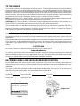
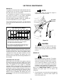
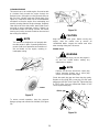
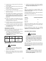
RECORDING MODEL AND SERIAL NUMBER INFORMATION
Product identification plates are provided for major components of your tractor. The numbers on these plates are
important if your tractor should require dealer service, or if you need additional information on your tractor. Prior to
using your tractor for the first time, record the numbers from the identification plates in the appropriate spaces pro-
vided below.
The chassis model plate, showing the factory model number and Mfg. Date (See Figure 1) can be found on the
underside of the seat mounting base. Pivot the seat foward to locate the decal.
The engine serial number decal (See Figure 2) is located on the engine blower housing.
Hood Model Factory Model No. Mfg. Date
Delivery Date Engine Model/Type Code.
Figure 1 Figure 2
www.cubcadet.com
CUB CADET LLC
P. O. BOX
361131
CLEVELAND, OH 44136
DEALER LOCATOR PHONE NUMBER:
877-282-8684
Model Number Mfg. Date
XXXXXXXXXXX XXXXXXXXXX
Engine Label

9
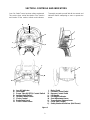
SECTION I. CONTROLS AND INDICATORS
Your Cub Cadet Tractor has been safety engineered.
This section gives a brief description of the function
and location of the various controls and indicators.
Thoroughly acquaint yourself with all the controls and
indicators before attempting to start or operate the
tractor.
A. Low Oil Indicator
B. Hour Meter
C. Power Take-Off (PTO) Control Switch
D. Ignition/Light Switch
E. Throttle Control Lever
F. Choke Control
G. Brake Pedal Lock
H. Cruise Control Lever
I. Brake Pedal
J. Forward Control Pedal
K. Reverse Control Pedal
L. Lift Handle
M. Lift Height Indicator
N. Seat Adjustment Lever
O. Transmission Release Lever
P. Fuses (Not Shown)
Q. Safety Interlock Switches (Not Shown)
Figure 3
AB
C
F
E
H
G
D
I
J
K
O
L
N
M

10
A. LOW OIL INDICATOR
This indicator will illuminate when the engine oil level is
low. If this indicator illuminates, stop the tractor imme-
diately and check the engine oil level. If the oil level is
within the operating range, but the light remains on,
contact your Cub Cadet dealer.
CAUTION
Operating the tractor with low oil level or pres-
sure could result in severe engine damage.
B. HOUR METER
The hour meter operates whenever the ignition key is
in the “ON” position. Record the actual hours of tractor
operation to ensure all maintenance procedures are
completed according to the schedule in this manual.
C. POWER TAKE–OFF (PTO) CONTROL SWITCH
The power take-off control switch operates the front
electric PTO clutch. Pull the switch knob to engage
(“RUN”), or push the knob to disengage (“OFF”) the
PTO clutch.
D. IGNITION/LIGHT SWITCH
WARNING
To prevent accidental starting and/or battery
discharge, remove the key from the ignition
switch when the tractor is not in use.
The combination lights and ignition switch is a four
position switch. (See Figure 4)
Figure 4
E. THROTTLE CONTROL LEVER
This lever controls the speed of the engine. When
set in a given position, the control cable will maintain
a uniform engine speed.
NOTE
When using power take-off operated equip-
ment, best performance is achieved with the
throttle lever in the “FAST” position.
F. CHOKE CONTROL
The choke control is operated manually. Pull the
knob out to ckoke the engine; push the knob in to
open the choke.
G. BRAKE PEDAL LOCK
WARNING
The hydrostatic transmission will not hold the
tractor on a hill. Normal internal leakage in the
transmission will allow the tractor to roll down-
hill. To avoid an accident and/or possible inju-
ry, engage the brake pedal lock.
The brake lock lever, located in the center of the
dash panel below the steering wheel, is identified
with the symbol. Always engage the brake
pedal lock when dismounting the tractor. To engage
the brake pedal lock, depress the brake pedal and
push down on the brake pedal lock lever. Hold the
lever down while releasing the brake pedal. The le-
ver should lock in the down position.
H. CRUISE CONTROL LEVER
The cruise control lever, located in the center of the
dash panel below the steering wheel, is identified with
the symbol. This lever can be used to main-
tain a desired “foot free” forward speed in areas
where constant speed changes are not required. Re-
fer to Section II- OPERATION for instructions on how
to use this feature.
This symbol shows slow position.
This symbol shows fast position.
P

11
I. BRAKE PEDAL
The brake pedal is located at the front of the right run-
ning board above the forward control pedal. Press
down to stop the tractor and disengage the cruise con-
trol. The brake pedal must be fully depressed to acti-
vate the safety interlock switch when starting the
tractor.
J. FORWARD CONTROL PEDAL
The forward control pedal is located at the front of the
right running board below the brake pedal. Slowly
press down on the pedal to start moving forward. The
forward ground speed of the tractor is directly affected
by the distance the pedal is depressed.
K. REVERSE CONTROL PEDAL
WARNING
Check behind the tractor to be sure the area is
clear of people, pets or obstacles. Use a slower
speed to maintain control of the tractor when
traveling in reverse.
The reverse control pedal is located in the right front
running board rearward of the the brake and forward
control pedals. Press the pedal downward to move in
reverse.
L. LIFT HANDLE
The lift handle is located in the left fender and is used
to raise and lower equipment used with the tractor. The
equipment can be set in any of six positions by de-
pressing the top button on the handle, moving the han-
dle to the desired position, then releasing the button. It
may be necessary to push or pull slightly on the handle
to depress the button. There is a lift assist spring which
reduces the effort needed to lift attachments. To adjust
spring tension refer to ADJUSTMENTS in Section III.
M. LIFT HEIGHT INDICATOR
The lift height indicator is located in the left fender and
indicates the height of the deck attachment when in-
stalled.
N. SEAT ADJUSTMENT LEVER
The seat adjustment lever (see Figure 5) is used to
move the seat forward or rearward into one of five po-
sitions. See ADJUSTING THE SEAT in Section III.
Figure 5
O. TRANSMISSION RELEASE LEVER
The transmission release lever is located at the back of
the tractor in the rear drawbar. This lever disconnects
the hydro transmission pump from the rear axle to al-
low the unit to be pushed a short distance by hand.
To disengage the transmission, pull back on the lever
until its locking flange is visible outside the drawbar,
then lift the lever up into the slot and release. To re-en-
gage the transmission, pull back on the lever, drop out
of the slot and release.
P. FUSES
The fuses are located under the hood between the in-
dicator lamps and the hour meter (see Figure 6). Fuses
are installed to protect the tractor’s electrical circuitry
and components from damage caused by excessive
amperage.
Figure 6

12
Q. SAFETY INTERLOCK SWITCHES
This tractor is equipped with a safety interlock system
for the protection of the operator. If the interlock sys-
tem should ever malfunction, do not operate the trac-
tor. Contact your authorized Cub Cadet Dealer. The
safety interlock system prevents the engine from
cranking or starting unless the brake pedal is fully de-
pressed, and the PTO switch is in the “OFF” position.
The safety interlock system will automatically shut off
the engine if the operator leaves the seat before en-
gaging the brake lock.
The safety interlock system will automatically shut off
the engine if the operator leaves the seat with the PTO
in the “RUN” position, regardless of whether the brake
lock is engaged. The PTO switch must be moved to the
“OFF” position to restart the engine.
The safety interlock system will automatically shut off
the PTO if the reverse control pedal is depressed with
the PTO in the “RUN” position. To re-engage the PTO,
release the reverse control pedal, move the PTO
switch to the “OFF” position, then again pull the switch
to the “RUN” position.
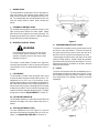
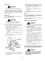
FUEL TANK
The fuel tank is located under the rear fender. The filler
cap is in the center/rear of the fender (see Figure 7).
Figure 7
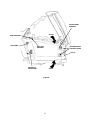
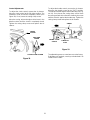
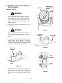
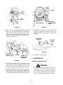
HOOD AND SIDE PANELS
The tractor hood is arranged to swing up and forward
for easy access to the engine compartment (see Fig-
ure 8). Whenever engine maintenance is required, the
side panels can be removed.
WARNING
If the engine has been recently run, the engine,
muffler and surrounding metal surfaces will be
hot and can cause burns to the skin. Allow the
tractor to cool and use caution when removing
the side panels.
To remove either the right or left side panel, refer to
Figure 8 and proceed as follows:
1. Engage the brake lock and raise the hood.
2. Loosen, but do not remove, the rear wing nut and
upper front wing nut.
3. Grasp the side panel just behind the grille and pull
outward to release the side panel from the
tapered bushings on the grille.
4. Slide the side panel forward and out of the groove
in the dash panel.
To install either the right or left side panel, refer to Fig-
ure 8 and proceed as follows:
1. Slide the rear of panel into the groove in the dash
panel.
2. Position the notch of the rear side panel tab on
the threads of the bulkhead rod, between the
bulkhead and wing nut.
3. Press the slots of the front side panel flange onto
the tapered retainers, between the retainers and
the grille.
4. Tighten the rear and upper front wing nuts and
close the hood.

13
Figure 8
UPPER FRONT
WING NUT
RETAINER WITH
TAPERED GUIDE
REAR WING NUT
GRILLE
REAR TAB
ON PANEL
SIDE PANEL
GROOVE IN
DASH PANEL
GRASP
GRASP

14
SECTION II. OPERATION
WARNING
Receive Instruction - Read the operator’s
manual. Learn to operate this machine
SAFELY. Don’t risk INJURY or DEATH.
1. Before starting the engine or beginning operation,
be familiar with the controls. The operator must be
seated, the PTO switch in the “OFF” position and
the brake pedal fully depressed.
2. Keep all shields in place. Keep away from moving
parts.
3. NO RIDERS! Keep all people and pets a safe
distance away. Look behind to both sides before
backing up.
4. DO NOT direct the mower discharge at people.
5. Avoid slopes. Tractors can be rolled over.
6. Before leaving the operator’s seat: Shut off the
PTO, engage the brake pedal lock, shut off the
engine and remove the ignition key. Wait for all
movement to stop before servicing or cleaning.
7. Do not fill the fuel tank when the engine is running
or while the engine is hot. Tighten the fuel cap
securely.
BEFORE OPERATING YOUR TRACTOR
1. Before you operate the tractor, study this manual
carefully. It has been prepared to help you operate
and maintain your tractor with utmost efficiency.
2. Familiarize yourself with the operations of all the
instruments and controls.
3. This engine is certified to operate on unleaded
gasoline. Fill the fuel tank with only clean, fresh,
unleaded gasoline with a minimum of 85 octane.
Do not mix oil with gasoline. Purchase fuel in a
quantity that can be used within 30 days to assure
fuel freshness.
In countries other than the U.S.A., leaded gasoline
may be used if it is commercially available and un-
leaded is not available.
NOTE: Some fuels, called oxygenated or reformulated
gasolines, are gasoline blended with alcohols or
ethers. Excessive amounts of these blends can dam-
age the fuel system or cause performance problems.
Do not use gasoline which contains Methanol. If any
undesirable operating symptoms occur, use gasoline
with a lower percentage of alcohol or ether.
4. Check the engine and transmission oil levels.
5. Clean the air cleaner element if necessary.
6. Check the tire inflation pressures.
7. Adjust the seat for operator’s maximum comfort,
visibility and for maintaining complete control of
the tractor.
8. Remove the side panels and clean any
accumulated grass and debris from the engine air
inlet screen. Also clean the dash air intake
screen, grille and side panels to ensure adequate
cooling.
9. Refer to the various sections of the Owner’s
Manual for additional information.
STARTING THE ENGINE
WARNING
For personal safety, the operator must be sitting
in the tractor seat when starting the engine.
WARNING
This unit is equipped with a safety inerlock
system designed for the protection of the
operator. Do not operate the tractor if any part
of the interlock system is malfunctioning.
Periodically check the functions of the interlock
system for proper operation as described
below:
• The safety interlock system prevents the en-
gine from cranking or starting unless the
brake pedal is fully depressed and the PTO
clutch engagement switch is in the “OFF” po-
sition.
• The safety interlock system will automatical-
ly shut off the engine if the operator leaves
the seat before engaging the brake pedal
lock.
• The safety interlock system will automatical-
ly disengage the PTO if the reverse control
pedal is pressed down with the PTO in the
“RUN” position. To re-engage the PTO, re-
lease the reverse control pedal, move the
PTO switch into the “OFF” position and then
engage the PTO while seated.
• The safety interlock system will automatical-
ly shut off the tractor engine if the operator
leaves the seat with the PTO in the “RUN”
position.

15
1. Operator must be sitting in the tractor seat.
2. Pull choke control knob to full choke position.
Less choking may be necessary due to variations
in temperature, grade of fuel, etc. Little or no
choking will be needed when the engine is warm.
3. Move the throttle lever to the “FAST” position.
4. Place the PTO switch in the “OFF” position.
5. Fully depress the brake pedal.
6. Turn the ignition key clockwise to the “START”
position and release it as soon as the engine
starts; however, do not crank the engine
continuously for more than 5 seconds at a time. If
the engine does not start within this time, turn the
key “OFF” and wait a minute to allow the engine’s
starter motor to cool, then try again.
7. After the engine starts, slowly release the brake
pedal. As the engine warms up, gradually push
the choke control knob all the way in. Do not use
the choke to enrich the fuel mixture, except as
necessary to start the engine.
NOTE
This engine is designed to give maximum
performance and service life if operated with the
choke fully open and the throttle in the “FAST”
position. To open the choke fully requires an
engine warmup period of several seconds to
several minutes, depending on the outdoor
temperature.
After starting the engine, push in the choke
control until the engine begins to run smoothly.
As the engine warms and begins to run roughly,
continue to push in the choke control as
necessary to keep the engine running smoothly
until the choke is fully depressed. Operating
equipment during engine warmup is not
recommended.
STOPPING THE ENGINE
CAUTION
Remove the key from the ignition switch to
prevent accidental starting or battery discharge
if the equipment is left unattended.
Place the PTO switch in the “OFF” position. Move the
throttle control lever between the “MID” and “FAST”
positions. Wait a moment to allow the engine speed to
stabilize, then turn the ignition key to the “OFF” posi-
tion. Remove the key from the ignition switch.
TRACTOR BREAK-IN PROCEDURE
CAUTION
Never operate a new engine immediately
under full load. Break it in carefully as shown
in the table below.
COLD WEATHER STARTING
WARNING
Engine exhaust gases are dangerous. Do not
run the engine in a confined area such as a
storage building any longer than is necessary.
Immediately move the tractor outdoors.
WARNING
For personal safety, the operator must be sitting
in the tractor seat before starting the tractor.
When starting the engine at temperatures near or below
freezing, ensure the correct viscosity motor oil is used in
the engine and the battery is fully charged. Start the en-
gine as follows:
1. Pull the choke all the way out to full choke position.
2. Move the throttle control lever to the “FAST”
position.
3. Place the PTO switch in the “OFF” position.
4. Fully depress the brake pedal.
Period
Engine Throttle
Control Lever
Position Load
1/2 3/4 Full
1st hour X None
2nd hour
X
X
Light drawbar load
or
Mowing with tractor
at slow groundspeed
3rd through
12th hour
X
X
Medium drawbar
load
or
Normal mowing

16
5. Turn the ingnition key to the “START” position and
hold until the engine starts; however, do not crank
the engine continuously for more than 5 seconds
at a time. Once the engine starts, gradually adjust
the choke as needed to keep the engine running until
warmed up, then push the choke control all the way
in.
NOTE
If the engine fails to start after several attempts,
the engine may become flooded. If this
happens, wait a minute to allow the starter
motor to cool. Move the throttle control to the
“SLOW” position, push the choke in all the way
and momentarily crank the engine to help clear
the cylinders. With the throttle control in the
“SLOW” position and the choke all the way in,
turn the ignition key to the “START” position
while slowly pulling the choke out to a position
that will allow the engine to start. Gradually
adjust the choke as needed to keep the engine
running until warmed up, then push the choke
control all the way in.
DRIVING THE TRACTOR
CAUTION
Avoid sudden starts, excessive speed and
sudden stops.
CAUTION
Do not leave the seat of the tractor without
disengaging the PTO, depressing the brake
pedal and engaging the brake pedal lock. If
leaving the tractor unattended, also turn the
ignition key off and remove the key.
NOTE
When using power take-off operated
equipment, best performance is achieved with
the throttle lever in the “FAST” position.
1. Depress the brake pedal to release the brake pedal
lock and let the pedal up. Move the throttle lever to
the position where the engine operates best for the
load to be handled.
2. Driving with forward or reverse pedals.
CAUTION
Do not use the forward or reverse control
pedals to change the direction of travel when
the tractor is in motion. Use the brake pedal to
bring the tractor to a stop before depressing
either the forward or reverse control pedal.
a. To move forward, slowly depress the forward
control pedal until the desired speed is
achieved.
b. To move in reverse, check that the area be-
hind is clear then fully depress the reverse
control pedal.
3. Using the cruise control lever.
NOTE
The cruise control feature can only be operated
in the forward direction.
a. Slowly depress the forward control pedal until
the desired speed is achieved.
b. Lightly push the cruise control lever downward
as far as possible and hold in this position.
c. While continuing to hold the cruise lever down,
lift your foot from the forward control pedal
(you should feel the cruise latch engage).
d. If properly engaged, the cruise lever and for-
ward control pedal should lock in the down po-
sition, and the tractor will maintain the same
forward speed.
e. Disengage the cruise control using one of the
following methods:
• Depress the brake pedal to disengage the
cruise control and stop the tractor.
• Lightly depress the forward control pedal.
• Lift the cruise control lever upward.
NOTE
Although not recommended, depressing the
reverse pedal will also disengage the cruise
control.
f. To change to the reverse direction when oper-
ating with cruise control, depress the brake
pedal to disengage the cruise control and stop
the tractor; then depress the reverse control
pedal.

17
DRIVING ON SLOPES
Refer to the SLOPE GAUGE on page 55 to help deter-
mine slopes where you may not operate safely.
WARNING
Do not mow on inclines with a slope in excess
of 15 degrees (a rise of approximately 2-1/2 feet
every 10 feet). The tractor could overturn and
cause serious injury.
WARNING
Operate the tractor up and down slopes, never
across slopes. Always drive up or down the face
of a slope. Do not drive so that the tractor may
tip over sideways .
Before operating the tractor on any slope, walk the
slope to look for possible hazards such as rocks.
mounds, ruts, stumps or other surface irregularities
which could cause the tractor to be upset.
Back the tractor with implement up the steepest portion
of each slope you intend to work. If the tractor cannot
negotiate the slope in reverse, the slope is too steep to
be worked.
Avoid turns when driving on a slope. If a turn must be
made, turn down the slope. Turning up a slope greatly
increases the chance of a roll over.
Avoid stopping when driving up a slope. If it is neces-
sary to stop while driving up a slope, start up smoothly
and carefully to reduce the possibility of flipping the
tractor over backward.
STOPPING THE TRACTOR
CAUTION
Always engage the brake pedal lock, push the
PTO switch to the “OFF” position, lower the
equipment and shut off the engine before
dismounting. Never try to start the engine while
standing on the ground.
Fully depress the brake pedal to bring the tractor to a
complete stop (and disengage the cruise control), en-
gage the brake pedal lock, disengage the PTO, turn
the ignition switch to “OFF’” and remove the key from
the switch before dismounting.
OPERATING THE POWER TAKE-OFF (PTO) CLUTCH
Before operating the new clutch under load (mowing
grass, etc.), perform the following break-in procedure:
1. Start and run the engine a few minutes to warm up.
2. With the mowing deck, snow thrower, etc. installed
and the engine running at approximately 50%
throttle, engage and disengage the clutch at ten
second intervals (ten seconds ON-ten seconds
OFF) five times. The engine choke may have to
be pulled out slightly to accomplish this.
3. Increase the engine speed to 75% throttle and
again engage and disengage the PTO clutch at
ten second intervals five times.
4. Make certain the PTO is disengaged and stop the
engine.
Operate the PTO clutch as follows:
1. Move the throttle control lever to approximately the
mid throttle position.
2. Pull the PTO switch to the “RUN” position.
3. Advance the throttle lever to the operating speed
(full engine speed).
4. The operator must remain in the tractor seat at all
times. If the operator should leave the seat
without turning off the power take-off switch, the
tractor’s engine will shut off.
5. The PTO clutch cannot be operated when the
tractor is driving in the reverse direction. The PTO
switch must in the “OFF” position when the
reverse control pedal is depressed, or the PTO
clutch will automatically disengage. To re-engage
the PTO clutch, release the reverse control pedal,
move the PTO switch to the “OFF” position, then
again pull the switch to the “RUN” position.
DRAWBAR
Drawbar type equipment must be hitched to the tractor
only at the hitch hole in the drawbar (See Figure 9).
Figure 9

18
SECTION III. ADJUSTMENTS
This section contains adjustment information for the
Model LT 2180 tractor. Adjustment information for the
42-inch deck is located in Section V – Mower Deck
beginning on page 33.
ADJUSTING THE SEAT
WARNING
Do not adjust the seat when the tractor is
moving. Adjusting the seat while the tractor is
moving could cause the operator to lose control
of the tractor.
Before starting the tractor, adjust the seat forward or
rearward to the most comfortable driving position. To
reposition the seat, move the seat adjustment lever
(see Figure 10) upward and slide the seat forward or
rearward. Release the adjustment lever when the seat
is comfortably positioned. Gently rock the seat forward
or rearward to be sure the seat is locked in place.
Figure 10
ADJUSTING THE BRAKES
During normal operation of this tractor, the brakes are
subject to wear and will need periodic examination and
adjustment.
To check the brake adjustment, position the tractor on
a firm and level surface. Stop the tractor engine and
remove the ignition key. Pull and lock the transmission
release lever in the “TRANSMISSION RELEASED”
position. Perform the following checks:
1. Engage the brake pedal lock. If the tractor can be
pushed forward or rearward, the braking force
must be increased.
2. Release the brake pedal lock. If the tractor cannot
be pushed forward or rearward, the braking force
must be decreased.
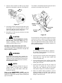
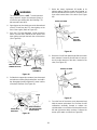
To adjust the braking force, refer to Figure 11 and
proceed as follows:
1. Place the tractor on a level surface with the brake
pedal lock disengaged. Stop the tractor engine
and remove the ignition key.
2. While working from the underside of the tractor,
facing the threaded end of the rod:
• Remove the internal cotter pin from the brake
rod adjustment ferrule and disconnect the fer-
rule from the brake cam.
• Loosen the hex jam nut from against the ferrule.
To increase the braking force—
Turn the ferrule clockwise (inward) one full turn at
a time until the ferrule can be inserted into the
brake cam while applying a minimal tension on
the spring.
To decrease the braking force—
Turn the ferrule counterclockwise (outward) one
full turn at a time until the ferrule can be inserted
into the brake cam while applying a minimal
tension on the spring.
3. Turn the ferrule counterclockwise (outward) one
full turn to release the slight spring tension.
Tighten the jam nut against the ferrule, then insert
the ferrule into the brake cam and secure with the
intenal cotter pin.
Figure 11. Viewed from top (fender off).
Recheck the brake adjustment to ensure proper brake
operation before operating the tractor. If brake rod
adjustment does not correct the problem, see your
authorized Cub Cadet dealer.
SPRING
BRAKE ROD
INTERNAL
COTTER PIN
ADJUSTMENT
FERRULE
BRAKE
CAM
HEX JAM NUT

19
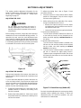
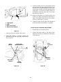
WHEEL ALIGNMENT
The front wheels should toe-in approximately 1/8 to
1/4 inch, as measured across dimensions A and B
shown in Figure 12.
Figure 12. Viewed from beneath the tractor.
FRONT WHEEL ADJUSTMENT
WARNING
Place the tractor on a firm and level surface.
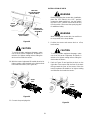
To adjust the toe-in, proceed as follows:
1. Check the lower steering arm to ensure it is
perpendicular to the tractor frame (See Figure 12).
2. Place a mark at the same spot on both front
wheels; preferably the inner bead flange of the
wheel rims.
3. Rotate the wheels to position the marks at the front
horizontal diameter of the wheels, then measure
the distance between the marks and the bottom
edges of the tractor frame channels (See
measurement D in Figure 12). These two
measurements should be equal.
4. While holding the steering arms to prevent the
steering knuckles from moving, rotate the marks to
the rear horizontal diameter. Measure the distance
between the marks and the frame (See
measurement C in Figure 12). Measurement D
should be approximately 1/16 to 1/8 inch less than
measurement C on each side of the tractor.
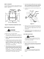
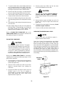
5. Disconnect the front ball joints from the steering
arms by removing the hex lock nuts (Refer to
Figure 13). Manually move each wheel to achieve
the required toe-in and equal D measurements.
6. Loosen the jam nuts from the ball joints (See
Figure 13).
Figure 13
7. Making sure not to move the lower steering arm or
either wheel, turn the ball joint in or out on each tie
rod as necessary to align with the hole in each
steering arm.
8. Reinstall the ball joints in the steering arms and
secure with the hex lock nuts. Tighten the jam nuts
against the ball joints.
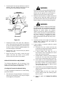
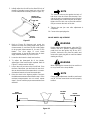
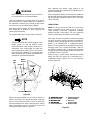
PIVOT BAR ADJUSTMENT
CAUTION
The tractor should be checked every 50 hours
of operation for play between the frame axle
channel and the pivot axle.
Check and adjust the pivot axle as follows:
1. Raise the front ot the tractor and set it on jack
stands, so the front wheels are suspended above
the ground.
CAUTION
For safety, block the rear wheels to prevent the
tractor from rolling and tipping or sliding the jack
stands.
PERPENDICULAR
TO FRAME
LOWER
STEERING
ARM
JAM NUT
STEERING
ARM
HEX
LOCK
NUT
BALL JOINT
TIE ROD

20
2. Pivot the ends of the axle up and down to check for
binding. If the axle is binding, loosen the lock nuts
(See Figure 14) until binding is eliminated.
Figure 14
3. Grasping the ends of the pivot axle, attempt to
move each end of the axle forward and rearward
to check for side play between the axle and frame
channel. If play is present, gradually tighten the
lock nuts until play is minimized.
4. Repeat steps 2 and 3 until minimum play without
binding is achieved.
5. Raise the front of the tractor, remove the jack
stands, and lower the tractor to the ground.
Remove the blocks from the rear wheels.
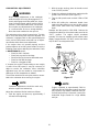
HYDROSTATIC NEUTRAL ADJUSTMENT
The following adjustments will be necessary if the
tractor creeps forward or rearward when neither the
forward nor reverse pedals are depressed.
Checking the Transmission Neutral Setting
To check and adjust the transmission neutral setting,
proceed as follows:
1. Drive the tractor for approximately 5-10 minutes to
warm up the transmission, then stop the engine
and engage the parking brake.
WARNING
Place the tractor on a firm and level surface and
chock the front wheels before raising the rear
wheels from the ground. Use jack stands to
support the rear of the tractor when raised.
2. Raise the rear of the tractor, so that the rear tires are
at least one inch above the surface, and set it on
jack stands. Make certain the jack stands are posi-
tioned to balance the tractor and prevent tipping.
WARNING
The operator presence safety circuit will stop
the engine if the seat is empty when the brake
pedal is released. If an assistant is seated when
adjusting the neutral setting, use extreme
caution to prevent the tractor from tipping or
rolling. Similar precautions should be taken with
any other method of over-riding the safety
circuit, such as placing a weight in the seat.
Never operate the tractor with the safety circuit
disabled.
3. Carefully start the tractor engine and release the
parking brake. Observe both rear wheels for
rotation in either direction.
4. If wheel rotation is observed, adjust the neutral
setting as follows:
a. Disconnect the rear control rod from the
control arm by removing the hairpin cotter from
the pivot sleeve (Refer to Figure 15).
b. If wheel rotation stops when the rod is
disconnected, check and readjust the control
rod per the instructions below.
c. If wheel rotation continues, loosen the locknut
securing the hex cap screw and centering
spacer to the neutral bracket (See Figure 15).
d. If the rotation is in the forward direction, slide
the centering spacer rearward until the wheels
just begin to rotate in the reverse direction.
Then slowly slide the spacer slightly forward
until wheel rotation stops.
e. If the rotation is in the reverse direction, slowly
slide the centering spacer slightly forward until
rotation stops.
f. Carefully tighten the hex cap screw and
locknut, making certain the centering spacer
does not move.
g. Stop the engine and engage the parking
brake.
SECTION A-A
PIVOT
AXLE
LOCK
NUTS
A
A
FRAME AXLE
CHANNEL
PIVOT AXLE
ADJUSTMENT BOLTS
LOCK
NUT
Page is loading ...
Page is loading ...
Page is loading ...
Page is loading ...
Page is loading ...
Page is loading ...
Page is loading ...
Page is loading ...
Page is loading ...
Page is loading ...
Page is loading ...
Page is loading ...
Page is loading ...
Page is loading ...
Page is loading ...
Page is loading ...
Page is loading ...
Page is loading ...
Page is loading ...
Page is loading ...
Page is loading ...
Page is loading ...
Page is loading ...
Page is loading ...
Page is loading ...
Page is loading ...
Page is loading ...
Page is loading ...
Page is loading ...
Page is loading ...
Page is loading ...
Page is loading ...
Page is loading ...
Page is loading ...
Page is loading ...
Page is loading ...
Page is loading ...
Page is loading ...
Page is loading ...
Page is loading ...
-
 1
1
-
 2
2
-
 3
3
-
 4
4
-
 5
5
-
 6
6
-
 7
7
-
 8
8
-
 9
9
-
 10
10
-
 11
11
-
 12
12
-
 13
13
-
 14
14
-
 15
15
-
 16
16
-
 17
17
-
 18
18
-
 19
19
-
 20
20
-
 21
21
-
 22
22
-
 23
23
-
 24
24
-
 25
25
-
 26
26
-
 27
27
-
 28
28
-
 29
29
-
 30
30
-
 31
31
-
 32
32
-
 33
33
-
 34
34
-
 35
35
-
 36
36
-
 37
37
-
 38
38
-
 39
39
-
 40
40
-
 41
41
-
 42
42
-
 43
43
-
 44
44
-
 45
45
-
 46
46
-
 47
47
-
 48
48
-
 49
49
-
 50
50
-
 51
51
-
 52
52
-
 53
53
-
 54
54
-
 55
55
-
 56
56
-
 57
57
-
 58
58
-
 59
59
-
 60
60


Cub Cadet 2000 Series User manual
- Category
- Lawnmowers
- Type
- User manual
- This manual is also suitable for
Ask a question and I''ll find the answer in the document
Finding information in a document is now easier with AI
Related papers
-
Cub Cadet ST54 FAB User manual
-
Cub Cadet LT42 CARB User manual
-
Cub Cadet RZT L Series User manual
-
-
-
-
-
-
-