Page is loading ...
JtVIPORTANT:
Read the Safety Guidelines
and All instructions Care-
fully Before Operating
I CRRFTSMIINI
120/240 VOLT _ 4250 WATT
• SAFETY GUUDELUNES
• ASSEMBLY
• OPERATUON
• MAUNTENANCE
• TROUBLESHOOTUNG
• REPAUR PARTS
SoBd by Sears Canada, inco, Tetente, Onto MSB2B8
MGP-670040 Rev. 0 12/6/99
DATEPURCHASED:
MODEL NO:
SERIAL NO:
STOREWHERE PURCHASED:
ADDRESS:
CITY:
TELEPHONE:
Record the above information about your unit
so that you will be abHe to provide it in case of
Hoss or theft.
HORSE POWER
GASOLINE CAPACITY
OiL CAPACITY
MAINTENANCE AGREEMENT
The Sears Warranty, pHusa Maintenance Agreement, pro-
vide maximum vaHuefor your Sears products. Contact
your nearest Sears store for detMHs.
CUSTOMER RESPONSiBiLiTiES
Read and observe the safety ruHes.
Follow a reguHarscheduHe in maintaining, caring for and
using your generator.
Follow the instructions under "Customer Responsibili-
ties" and "Storage" sections of this owner's manual.
FULL ONE YEAR WARRANTY ON CRAFTSMAN GENERATORS
For one year from the date of purchase, when this Craftsman generator is maintained and operated according to the instruc-
tions in this owner's manual, Sears wilI repair, free of charge, any defect in material and workmanship.
if your Craftsman Generator is used for commercia! or rentaJ purposes, this warranty applies for only 90 days from the original
date of purchase.
FULL ONE YEAR WARRANTY ON CRAFTSMAN ENGINE
For one year from the date of purchase, when this Craftsman engine is maintained and operated according to the instructions
in this owner's manual, Sears will repair, free of charge, any defect in material and workmanship.
if your Craftsman engine is used for commercia! or rental purposes, this warranty applies only for 90 days from thedate of
purchase. This warranty does not cover: Expendable items such as spark plugs and air filters, which become worn during
normaJ use.
Repairs necessary because of operator abuse or negligence, including damage resulting from no oil being supplied to
the engine or failure to maintain the equipment according to the instructions contained in this owner's manual, are not
covered under warranty.
WARRANTY SERVICE IS AVAILABLE BY RETURNING THE GENERATOR TO THE NEAREST SEARS SERVICE CENTER. This
warranty gives you specific legal rights and you may also have other rights, which vary from PROVINCE TO PROVINCE.
Sold by Sears Canada, inc., Toronto, Ont.
MGP670040 2 -- ENG

This manuaH contains information that is important for you to know and understand. This information reHatesto
protecting YOUR SAFETY and PREVENTING EQUIPMENT PROBLEMS. To heHpyou recognize this information,
we use the symboHs to the right. Hease read the manuaH and pay attention to these sections.
DANGER indicates an imminently hazardous situation
which, if not avoided, will result in death or serious
WARNING indicates a potentially hazardous situation
which, if not avoided, coumdresult in death of serious
CAUTION indicates a potentially hazardous situation
which, if not avoided, _ result in minor or moderate
CAUTION used without the safety alert symbol indicates a
potentially hazardous situation which, if not avoided,
result in
This product is not equipped with a spark arresting muffler. If the product wi[[ be used around flammable
materials, or on land covered with materials such as agricultural crops, forest, brush, grass, or other similar items,
then an approved spark arrester must be installed and may be legally required in other countries.
SAVE THin=St=iNSTRUCTiONS
When using this product basic precautions should always be
followed including the following:
HAZARD
RBSK OF ELECTROCUTBON AND FBRE
WNAT COULD NAPPEN NOW TO PREVENT iT
Never backfeed electricity through
a structure's electrical system.
Back feeding electricity through a
building's electrical system to the
outside utility feed lines could en-
danger repair persons attempting to
restore service.
Attempting to connect to the incom-
ing utility service could result in
electrocution.
Restoration of electrical service while
the generator is connected to the
incoming utility could result in a fire or
serious damage if a isolator switch is
not installed.
Attempting to connect generator di-
rectly to the electrical system of any
building structure.
Failure to use a double throw transfer
switch when connecting to a struc-
tures electrical system can damage
appliances and WILL VOiD the
manufacturers warranty.
To connect to a structure's electri-
cal system in a safe manner,
always have a Double-Throw
Transfer Switch installed by a
qualified electrician and in compli-
ance with local ordinances. {When
installing a Double-Throw
Transfer Switch, a minimum of
10 gauge wiring must be used.)
3 -- ENG MGP_;70040
READ AN{) UNDERSTAND ALL WARNmNG$ BEFORE
ATTEMPTBNG TO OPERATE GENERATOR°
RBSK OF ELECTROCUTBON AND FBRE .(cont'd}
HAZARD
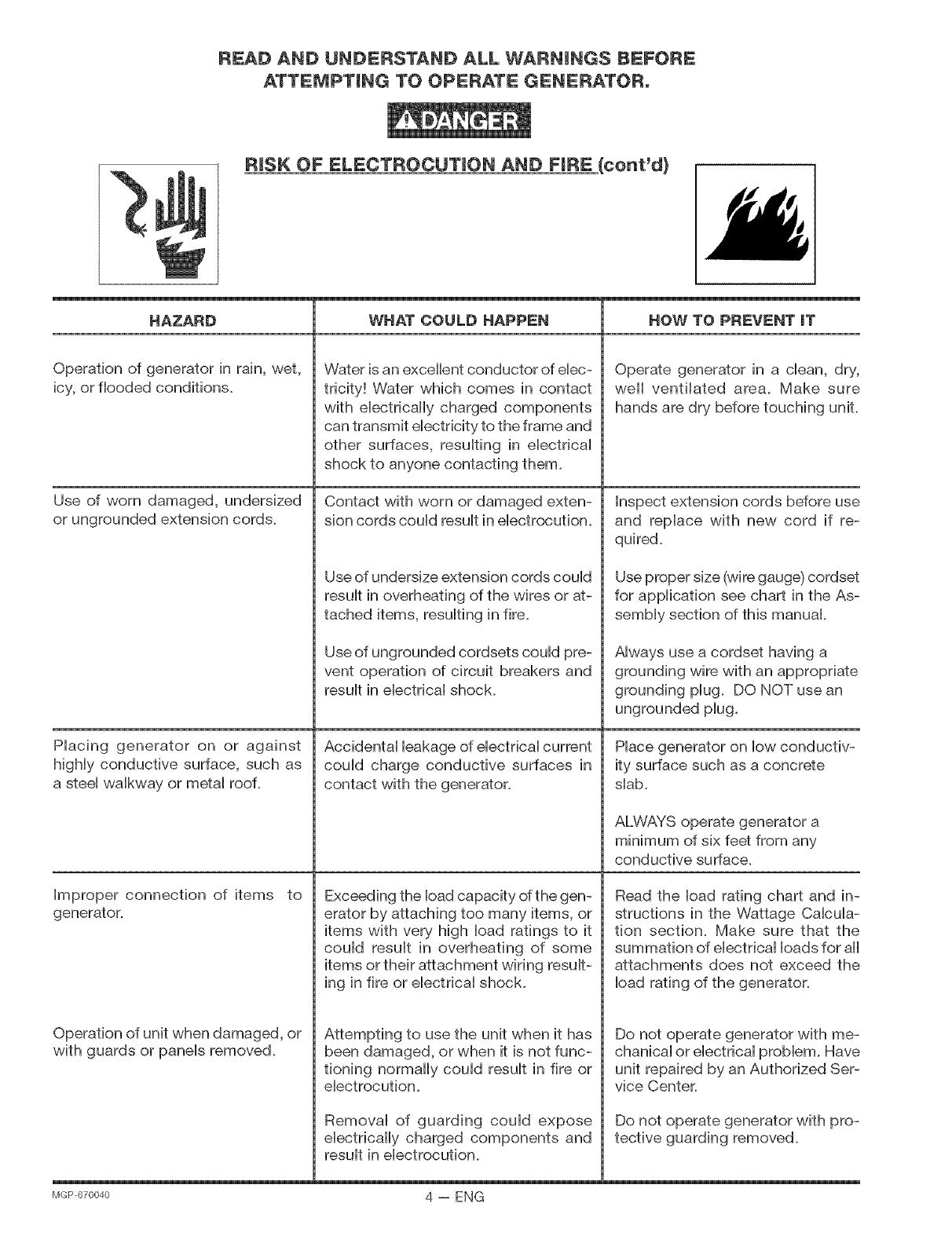
Operation of generator in rain, wet,
icy, or flooded conditions.
Use of worn damaged, undersized
or ungrounded extension cords.
Piacing generator on or against
higHy conductive surface, such as
a steei waikway or metai roof.
Improper connection of items to
generator.
Operation of unit when damaged, or
with guards or paneb removed.
WHAT COULD HAPPEN
Water is an excellent conductor of ebc-
tricity! W/ater which comes in contact
with electrically charged components
can transmit electricity to the frame and
other surfaces, resulting in electrical
shock to anyone contacting them.
Contact with worn or damaged exten-
sion cords could result in electrocution.
Use of undersize extension cords could
result in overheating of the wires or at-
tached items, resulting in fire.
Use of ungrounded cordsets could pre-
vent operation of circuit breakers and
result in electrical shock.
Accidental leakage of electrical current
could charge conductive surfaces in
contact with the generator.
Exceeding the load capacity of the gen-
erator by attaching too many items, or
items with very high load ratings to it
could result in overheating of some
items or their attachment wiring result-
ing in fire or electrical shock.
Attempting to use the unit when it has
been damaged, or when it is not func-
tioning normally could result in fire or
electrocution.
Removal of guarding could expose
electrically charged components and
result in electrocution.
HOW TO PREVENT iT
Operate generator in a clean, dry,
well ventilated area. Make sure
hands are dry before touching unit.
Inspect extension cords before use
and replace with new cord if re-
quired.
Use proper size (wire gauge) cordset
for application see chart in the As-
sembly section of this manual
Always use a cordset having a
grounding wire with an appropriate
grounding plug. DO NOT use an
ungrounded plug.
Place generator on low conductiv-
ity surface such as a concrete
slab.
ALWAYS operate generator a
minimum of six feet from any
conductive surface.
Read the load rating chart and in-
structions in the Wattage Calcula-
tion section. Make sure that the
summation of electrical loads for all
attachments does not exceed the
load rating of the generator.
Do not operate generator with me-
chanical or electrical problem. Have
unit repaired by an Authorized Ser-
vice Center.
Do not operate generator with pro-
tective guarding removed.
MGP670040 4 -- ENG

READ AND UNDERSTAND ALL WARNINGS BEFORE
ATTEMPTBNG TO OPERATE GENERATOR°
RiSK OF FiRE
HAZARD
Attempting to fill the fuel tank while
the engine is running.
Sparks, fire, hot objects
Improper storage of fuel
Inadequate ventilation for genera-
tor
Tampering with factory set engine
speed settings.
Overfilling the fuel tank -
fuel spillage.
WHAT COULD HAPPEN
Gasoline and gasoline vapors can
become ignited by coming in contact
with hot components such as the
muffler, engine exhaust gases, or from
an electrical spark.
Cigarettes, sparks, fires, or other hot
objects can cause gasoline or gaso-
line vapors to ignite.
Improperly stored fuel could lead to
accidental ignition. Fuel improperly
secured could get into the hands of
children or other unqualified persons.
Materials placed against or near the
generator or operating the generator
in areas where the temperature
exceeds 104 ° R ambient (such as
storage rooms or garages) can
interfere with its proper ventilation
features causing overheating and
possible ignition of the materials or
buildings.
Engine speed has been factory set to
provide safe operation. Tampering
with the engine speed adjustment
could result in overheating of attach-
ments and could cause a fire.
Spilled fuel and its vapors can be-
come ignited from hot surfaces or
sparks.
HOW TO PREVENT iT
Turn engine off and allow it to cool
before adding fuel to the tank.
Equip area of operation with a fire
extinguisher certified to handle
gasoline or fuel fires.
Add fuei to tank in weii ventilated
area. Make sure there are no
sources of ignition near the
generator.
Store fuel in a OSHA approved
container designed to hold gaso-
line. Store container in secure
location to prevent use by others.
Operate generator in a clean, dry,
weii ventilated area a minimum of
four feet from any building, object
or waii. DO NOT OPERATE UNiT
iNDOORS OR iN ANY CON=
FINED AREA.
Never attempt to "speed=up" the
engine to obtain more perfor-
mance. Both the output voltage
and frequency wiil be thrown out
of standard by this practice,
endangering attachments and the
user.
Use care in filling the tank to avoid
spilling fuel. Make sure fuel cap is
secured tightly and check engine
for fuel leaks before starting
engine. Move generator away
from refueling area or any spillage
before starting engine. Allow for
fuel expansion. Keep maximum
fuel level 1Ainch below the tip of
the fuel tank. Never refuel with the
5 -- ENG lvlGP670040
READ AND UNDERSTAND ALL WARNNNG$ BEFORE
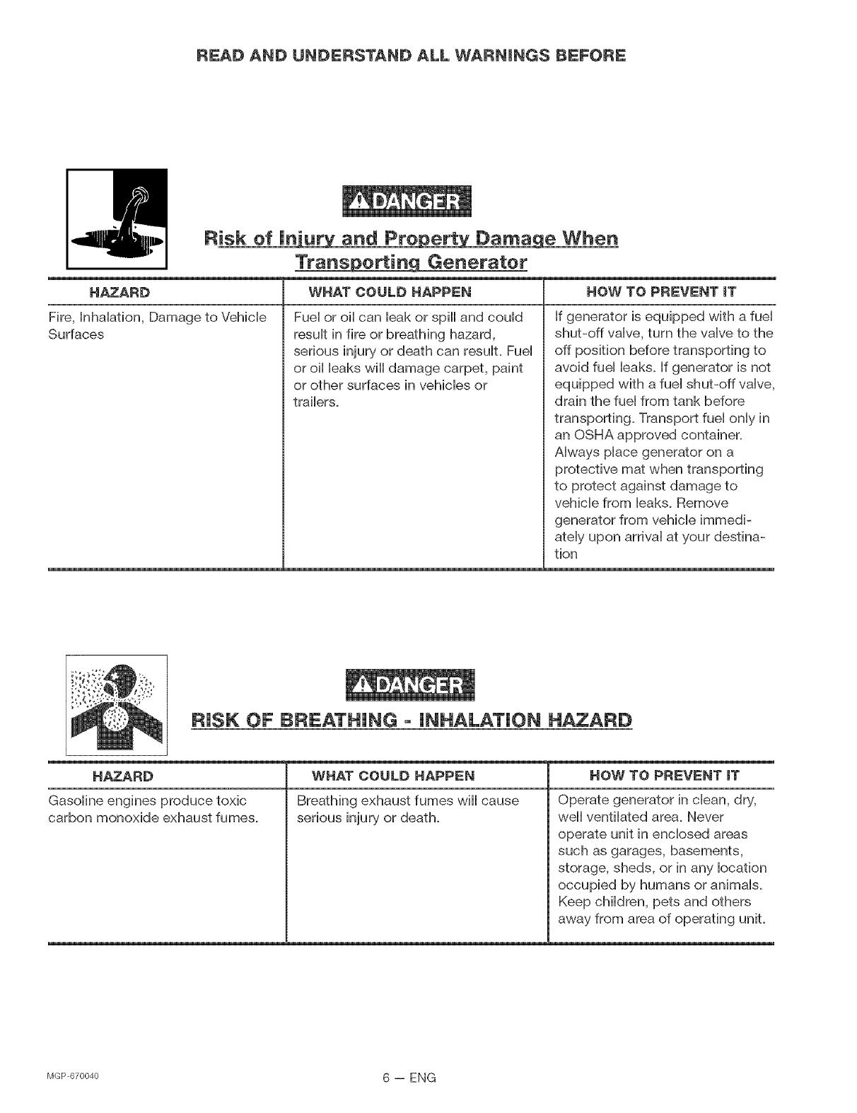
Risk of in'u.Lu_r_zand Proeper_vtDa_ao_lLe When
Trans_q Generater
WHAT COULD HAPPEN
Fuei or oii can bak or spill and couid
resuit in fire or breathing hazard,
serious injury or death can resuit. Fuei
or oii baks will damage carpet, paint
or other surfaces in vehbbs or
traibrs.
HAZARD
Fire, hhaiation, Damage to Vehicle
Surfaces
HOW TO PREVENT iT
If generator is equipped with a fuel
shut-off valve, turn the valve to the
off position before transporting to
avoid fuel leaks. If generator is not
equipped with a fuel shut-off valve,
drain the fuel from tank before
transporting. Transport fuel only in
an OSHA approved container.
Always place generator on a
protective mat when transporting
to protect against damage to
vehicle from leaks. Remove
generator from vehicle immedi-
ately upon arrival at your destina-
tion
RISK OF BREATHING - INHALATION HAZARD
HAZARD
Gasoline engines produce toxic
carbon monoxide exhaust fumes.
WHAT COULD HAPPEN
Breathing exhaust fumes will cause
serious injury or death.
HOW TO PREVENT iT
Operate generator in clean, dry,
weii ventilated area. Never
operate unit in enclosed areas
such as garages, basements,
storage, sheds, or in any location
occupied by humans or animals.
Keep children, pets and others
away from area of operating unit.
bIGP 670040 6 -- ENG
READ AND UNDERSTAND ALL WARNINGS BEFORE
ATTEMPTBNG TO OPERATE GENERATOR°
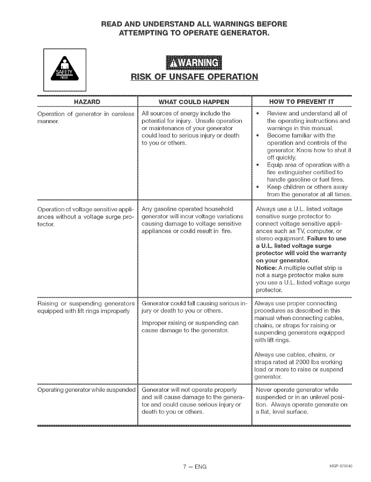
RiSK OF UNSAFE OPERATION
HAZARD
Operation of generator in carebss
manner.
Operation of voitage sensitive appii-
ances without a voitage surge pro-
tector.
Raising or suspending generators
equipped with iift rings improperly
Operating generator wNe suspended
WHAT COULD HAPPEN
AHsources of energy include the
potential for injury. Unsafe operation
or maintenance of your generator
could lead to serious injury or death
to you or others.
Any gasoline operated household
generator wiii incur voltage variations
causing damage to voltage sensitive
appliances or could result in fire.
Generator could fall causing serious in-
jury or death to you or others.
Improper raising or suspending can
cause damage to the generator.
Generator wiii not operate properly
and wiii cause damage to the genera-
tor and could cause serious injury or
death to you or others.
HOW TO PR_:V_:NT iT
Review and understand all of
the operating instructions and
warnings in this manual.
Become familiar with the
operation and controls of the
generator. Know how to shut it
off quickly.
Equip area of operation with a
fire extinguisher certified to
handle gasoline or fuel fires.
o Keep children or others away
from the generator at all times.
Always use a U.L listed voltage
sensitive surge protector to
connect voltage sensitive appli-
ances such as TV, computer, or
stereo equipment, Failure to use
a U,L, listed voltage surge
protector will void the warranty
on your generator°
Notice: A multiple outlet strip is
not a surge protector make sure
you use a U.L listed voltage surge
9rotector.
Always use proper connecting
srocedures as described in this
manual when connecting cables,
chains, or straps for raising or
suspending generators equipped
with lift rings.
Always use cables, chains, or
straps rated at 2000 Ibs working
load or more to raise or suspend
generator.
Never operate generator while
suspended or in an unievei posi-
tion. Always operate generate on
a fiat, level surface.
7 -- ENG lvlGPc_70040
REAO ANO UNDERSTAND ALL WARNINGS BEFORE
ATTEMPTBNG TO OPERATE GENERATOR°
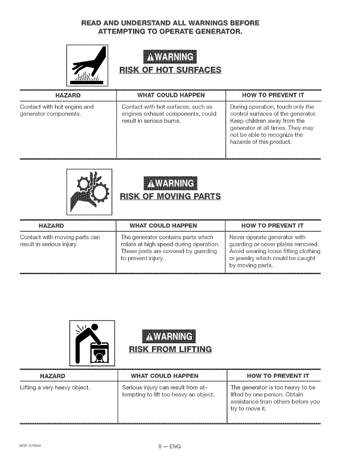
RiSK OF HOT SURFACES
HAZARD
Contact with hot engine and
generator components.
WHAT COULD HAPPEN
Contact with hot surfaces, such as
engines exhaust components, could
result in serious burns.
HOW TO PREVENT iT
During operation, touch only the
control surfaces of the generator.
Keep children away from the
generator at all times. They may
not be able to recognize the
hazards of this producL
RiSK OF MOVING PARTS
HAZARD
Contact with moving parts can
result in serious injury.
WHAT COULO HAPPEN
The generator contains parts which
rotate at high speed during operation.
These parts are covered by guarding
to prevent injury.
HOW TO PREVENT iT
Never operate generator with
guarding or cover plates removed.
Avoid wearing loose fitting clothing
or jewelry which could be caught
by moving parts.
I _ i RiSK FROM LiFTiNG
HAZARD WHAT COULD HAPPEN HOW TO PREVENT iT
Lifting a very heavy object. Serious injury can result from at- The generator is too heavy to be
tempting to lift too heavy an objecL lifted by one person. Obtain
assistance from others before you
try to move it.
MGP670040 8 -- ENG

CARTON CONTENTS ° Parts Bag
t - Generator
1 ° Parts Box
f ....
t - Handle
"t - TwistJock Plug LS-20P
t = Owner's ManuaJ
"t = Twistloek PJug L14-20P
* _ To be installed and/or used in
accordance with appropriate HocaHeHectricaHcodes
and regubfions. Refer to enclosed instructions for
proper installation.
t =isolator Foot 7 =5/16-t8 x 3/4 " 9 - 5/t6=t8
Cap Screws Lock Nuts
(6 used)
2 = Washers 2 - 3/8ot6
Lock Nuts
Read owner's manual. Do not attempt to operate equipment until you have read Owner's
Manual for Safety, Assembly, Operation, Maintenance, Storage Instructions.
NOTE: Left and right describes the location of a part
with the operator facing the outlet panel.
TOOLS NEEDED FOR ASSEMBLY
1- Box Cutter or Knife
2 - 1/2" Wrenches
2 - 9/16" Wrenches
1 - 1" thick x 1' square piece of wood
REMOVE GENERATOR FROM CARTON
Open carton from top.
Cut carton along dotted lines.
Remove all carton inserts.
Remove generator through opening in carton.
iMPORTANT: Before any attempt to start your genera-
tor be sure to check engine oil (See Adding Engine Oil
paragraph in the Operation section on page 13 of this
manual.)
9 -- ENG MGP670040
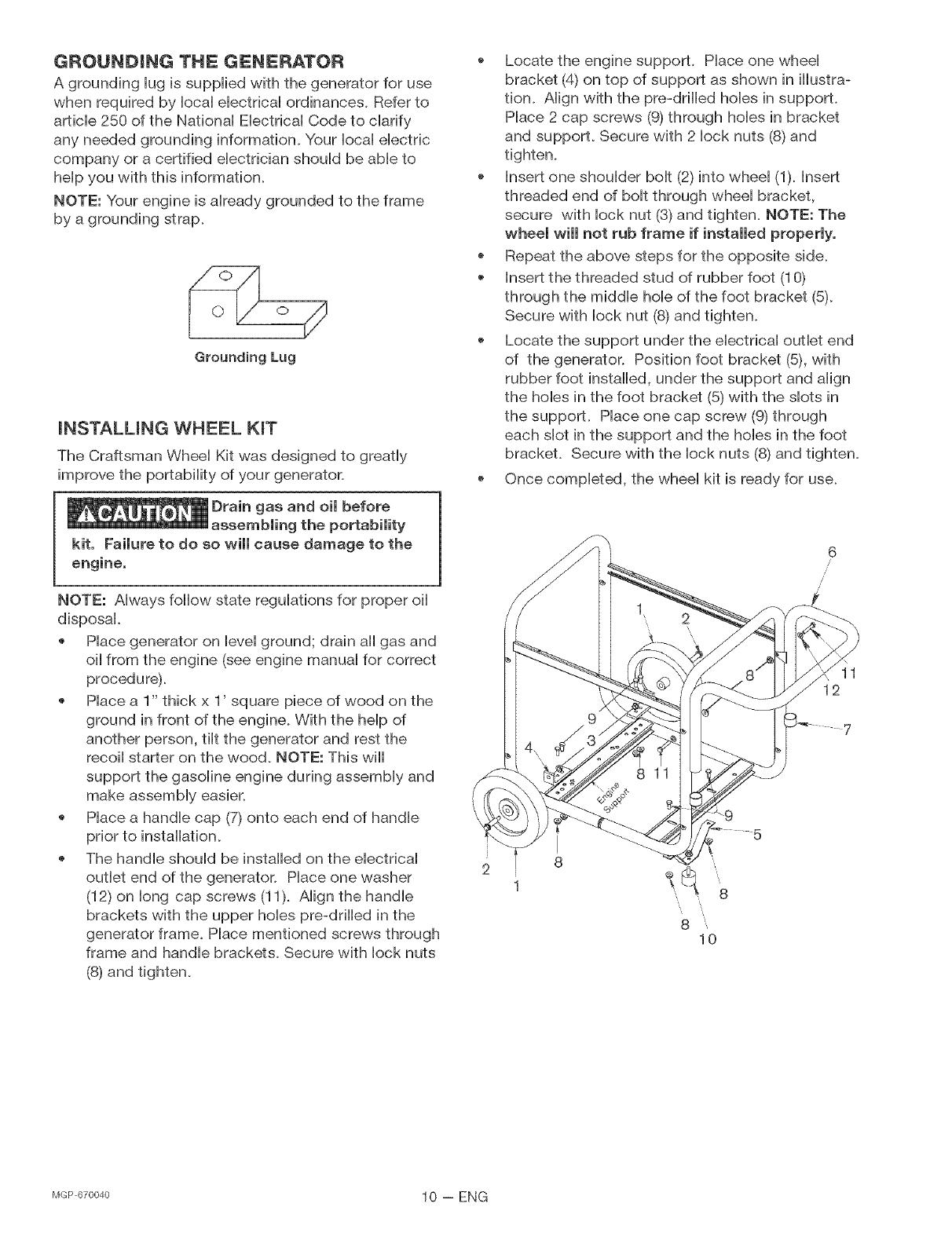
GROUNDBNG THE GENERATOR
A grounding lug is supplied with the generator for use
when required by local electrical ordinances. Refer to
article 250 of the National Electrical Code to clarify
any needed grounding information. Your local electric
company or a certified electrician should be able to
help you with this information.
NOTE: Your engine is already grounded to the frame
by a grounding strap.
Grounding Lug
mNSTALUNG WHEEL KmT
The Craftsman Wheel Kit was designed to greatly
improve the portability of your generator.
Drain gas and oimbefore
assembming the portabimity
kit. Faimure to do so wimmcause damage to the
engine.
NOTE: Always follow state regulations for proper oil
disposal.
Place generator on level ground; drain all gas and
oil from the engine (see engine manual for correct
procedure).
Place a 1" thick x 1' square piece of wood on the
ground in front of the engine. With the help of
another person, tilt the generator and rest the
recoil starter on the wood. NOTE: This will
support the gasoline engine during assembly and
@
o
Place a handle cap (7) onto each end of handle
prior to installation.
The handle should be installed on the electrical
outlet end of the generator. Place one washer
(12) on long cap screws (11). Align the handle
brackets with the upper hobs pre-drilled in the
generator frame. Place mentioned screws through
frame and handle brackets. Secure with lock nuts
(8) and tighten.
o Locate the engine support. Place one wheel
bracket (4) on top of support as shown in iiiustra-
tion. Align with the pre-drilled hobs in support.
Place 2 cap screws (9) through holes in bracket
and support. Secure with 2 lock nuts (8) and
tighten.
Insert one shoulder bolt (2) into wheel (1). Insert
threaded end of bolt through wheel bracket,
secure with lock nut (8) and tighten. NOTE: The
wheemwimmnot rub frame if inatammedpropermy.
* Repeat the above steps for the opposite side.
Insert the threaded stud of rubber foot (10)
through the middle hob of the foot bracket (5)_
Secure with lock nut (8) and tighten.
Locate the support under the electrical outlet end
of the generator. Position foot bracket (5), with
rubber foot installed, under the support and align
the hobs in the foot bracket (5) with the dots in
the support. Place one cap screw (9) through
each dot in the support and the hobs in the foot
bracket. Secure with the lock nuts (8) and tighten.
Once completed, the wheel kit is ready for use.
6
/
/
/
11
12
b1<_p67oo4o 10 -- ENG
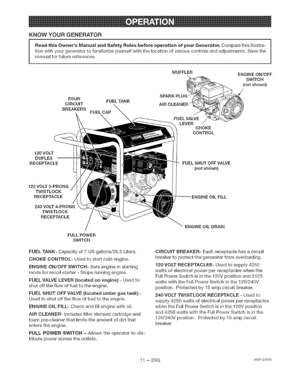
KNOW YOUR GENERATOR
Read this Owner's Manua_ and Safety Ru_es before operation of your Generator, Compare this illustra-
tion with your generator to famiHiarize yourseff with the location of various controHs and adjustments. Save the
manual for future references.
FOUR
CiRCUiT
BREAKERS
FUEL CAP
FUEL TANK
MUFFLER
FUEL VALVE
LEVER
CHOKE
CONTROL
ENGINE ON/OFF
SWITCH
(not shown)
/
120 VOLT
DUPLEX
RECEPTACLE FUEL SHUT OFF VALVE
(not shown)
120 VOLT 3-PRONG
TWESTLOCK
RECEPTACLE
240 VOLT 4-PRONG
TWESTLOCK
RECEPTACLE
FULL POWER
SWITCH
FUEL TANK- Capacity of 7 US gallons/26.5 Liters.
CHOKE CONTROL- Used to start coHd engine.
ENGINE ON/OFF SWITCH- Sets engine in starting
mode for recoiHstarter - Stops running engine.
FUEL VALVE LEVER (located on engine) - Used to
shut off the flow of fueHto the engine.
FUEL SHUT OFF VALVE (located under gas tank) -
Used to shut off the flow of fuel to the engine.
ENGINE OiL FILL- Check and fill engine with oil.
AIR CLEANER- Includes filter element cartridge and
foam pre-cleaner that limits the amount of dirt that
enters the engine.
FULL POWER SWITCH - Allows the operator to dis-
tribute power across the outlets.
OiL FiLL
ENGINE OIL DRAIN
CiRCUiT BREAKER- Each receptacle has a circuit
breaker to protect the generator from overloading.
120 VOLT RECEPTACLES- Used to supply 4250
watts of electrical power per receptacles when the
Full Power Switch is in the 120V position and 2125
watts with the Full Power Switch in the 120/240V
position. Protected by 15 amp circuit breaker.
240 VOLT TWISTLOCK RECEPTACLE - Used to
supply 4250 watts of electrical power per receptacles
when the Full Power Switch is in the 120V position
and 4250 watts with the Full Power Switch is in the
120/240V position. Protected by 15 amp circuit
breaker.
11 -- ENG NGP670040

Your generator is equipped with:
one 120 volt duplex receptacle protected by a 15
amp circuit breaker
one 120 volt 3-prong twist[ock receptacle pro-
tected by a two 15 amp circuit breakers
one 240 volt 4-prong twist[ock receptacle pro-
tected by two 15 amp circuit breakers
The circuit breakers are provided to protect the
generator against electrical overload. If the circuit
breaker trips, unplug electrical load from receptacle.
Let circuit breaker coo[ down and then push circuit
breaker button to reset.
r_Er_,l__/42o
FULL POWER SWmTCH
When placed in the 120V position it allows you to
receive the fuji capacity of the generator by using a[[
120 volt receptacles. When in the 120/240 position,
you wi[[ only be able to receive 2125 watts when using
the 120 volt receptacles and the fuji 4250 watts when
using the 240 4-prong twist[ock receptacle.
Full Power Switch in the 120V/240V position
120V 15A 120V 240V 15A
120V 15A (_) ®
120v A( ® NEMAL -20RNEMAL14-20R®
NEMA 5-20R 3=prong 4=prong 120V
Duplex Twist[oek TwistBoek
2125 Watts 2125 Watts 4250 Watts
120/240V
Full Power Switch in the 120V position
®
120v A ®
NEMA 5-20R
DupBex
4250 Watts Surge
2125 continues
120V 15A 120V 240V 15A
®
®
NEMA L5-20R NEMA L14-20R --
3=prong 4=prong 120v 120/240v
Twistioek TwistBoek
4250 Watts surge together
2125 Watts continuous together
No 240V available
LOW OIL SHUTDOWN
Your Craftsman generator engine is equipped with Low
Oil Shutdown. Low Oil Shutdown is a safety device
designed to protect your engine from damage in the
event the oil [eve[ in the crankcase is low.
If while the engine is running, the oil gets low, it wi[[
automatically shut itself down and wi[[ not restart until
the oil is added. If the oil is low before start-up, the
generator wi[[ not start until oil is added.
NOTE: The Low Oil Shutdown mechanism is very sensi-
tive. You must fi[[ the engine to the fuji mark on the dip-
stick to inactivate this safety device.
GENERATOR CAPACITY
Exceeding the rated capacity of your generator can
result in serious damage to your generator and con-
nected electrical devices. You should observe the
following to prevent overloading the unit:
Starting and running wattage requirements should
always be calculated when matching a generators
wattage capacity to the appliance or too[.
There are two types of electrical appliances that
can be powered by your generator:
A. Items such as radios, light bulbs, television
sets, and microwaves have a "resistive load".
Starting wattage and running wattage are the
same.
B_
Items such as refrigerators, air compressors,
washer, dryer, and hand tools that use an
electrical motor have an "inductive load".
Inductive load appliances and tools require
approximately 2 to 4 times the listed wattage
for starting the equipment. This initial load
only lasts for a few seconds on start-up but is
very important when figuring your total watt-
age to be used.
MGP670040 12 -- ENG
NOTE: Some inductive appHiances and tooHswill Hist
on the motor name plate, the starting and running
voHtage and amperage requirements. Use the following
formuHato convert voHtage and amperage to wattage:
{Volts X Amp = Watts}
AHways start your HargesteHectric motor first, and
then pHugin other items, one at a time.
NOTE: On 120-voHt Hoadsthe maximum starting watt-
age shouM NOT exceed one haHfof the rated generator
wattage. ExampHe: a 4250 rated wattage generator =
2125 maximum starting wattage.
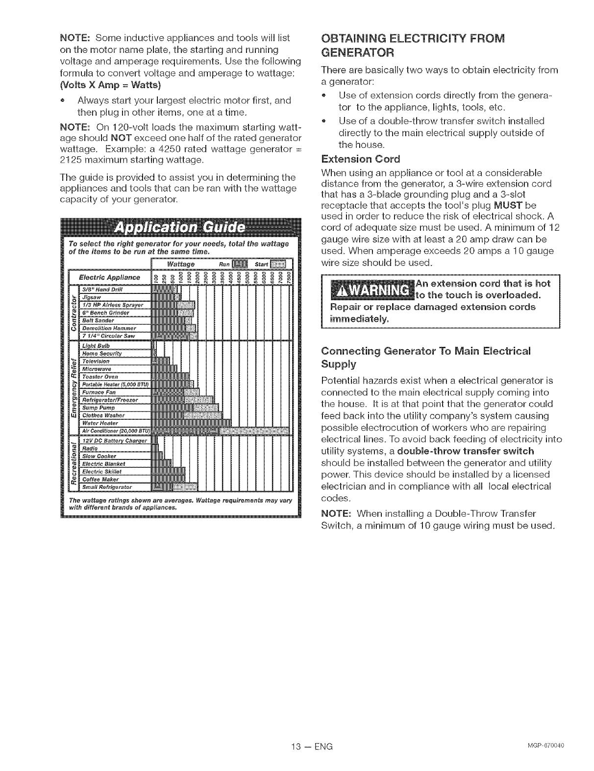
The guide is provided to assist you in determining the
appHiances and tooHsthat can be ran with the wattage
capacity of your generator.
OBTAiNiNG ELECTRiCiTY FROM
GENERATOR
There are basically two ways to obtain electricity from
a generator:
Use of extension cords directly from the genera-
tor to the appliance, lights, tools, etc.
Use of a double-throw transfer switch installed
directly to the main electrical supply outside of
the house.
Extension Cord
When using an appliance or tool at a considerable
distance from the generator, a 3-wire extension cord
that has a 3-blade grounding plug and a 3-dot
receptacle that accepts the tool's plug MUST be
used in order to reduce the risk of electrical shock. A
cord of adequate size must be used. A minimum of 12
gauge wire size with at least a 20 amp draw can be
used. When amperage exceeds 20 amps a 10 gauge
wire size should be used.
An extension cord that is hot
to the touch is overloaded.
Repair or replace damaged extension cords
Connecting Generator To Main Electrical
Supply
Potential hazards exist when a electrical generator is
connected to the main electrical supply coming into
the house. It is at that point that the generator could
feed back into the utility company's system causing
possible electrocution of workers who are repairing
electrical lines. To avoid back feeding of electricity into
utility systems, a double-throw transfer switch
should be installed between the generator and utility
power. This device should be installed by a licensed
electrician and in compliance with all local electrical
codes.
NOTE: When installing a Double-Throw Transfer
Switch, a minimum of 10 gauge wiring must be used.
13 -- ENG lvlGP670040
BEFORE STARTmNG ENGmNE
Always check engine oil level
before every start. Running
ine low of oil or out of oil could result in
serious damage to the engine.
eng
Adding Engine OH
Your generator has been shipped without oii in the
To add oii:
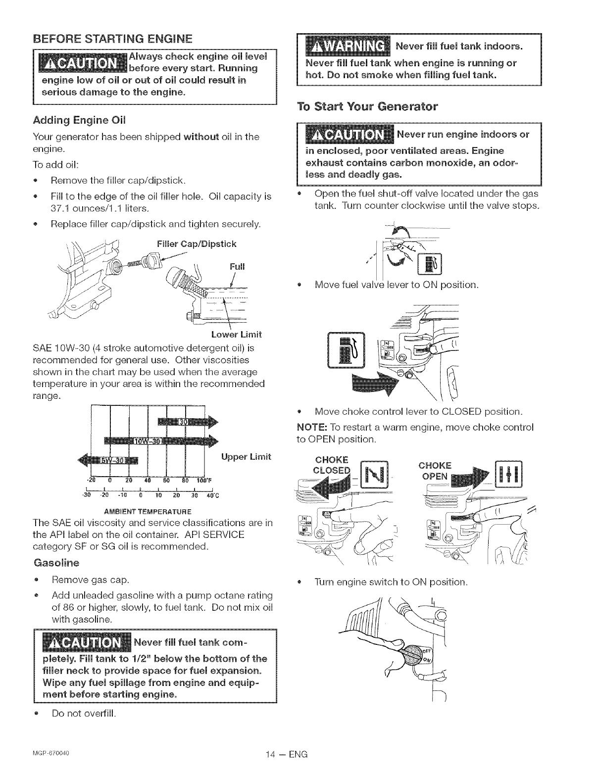
Remove the fiiier cap/dipstick.
Fiii to the edge of the oil filler hob. Oil capacity is
37.1 ounces/1.1 liters.
Replace filler cap/dipstick and tighten securely.
Filler Cap/Dipstick
Never fimmfuemtank indoors.
Never fill fuemtank when engine is running or
hot. Do not smoke when filling fuel tank.
To Start Your Generator
Never run engine indoors or
in enclosed, poor ventilated areas. Engine
exhaust contains carbon monoxide, an odor=
less and deadmy gas.
Open the fuel shut-off valve located under the gas
tank. Turn counter clockwise until the valve stops.
Move fuel valve lever to ON position.
Lower Limit
SAE 10W-30 (4 stroke automotive detergent oil) is
recommended for general use. Other viscosities
shown in the chart may be used when the average
temperature in your area is within the recommended
range.
i
I
_ _ B ___ _ Upper Limit
- .'_ 20 48 _ 80 180°F
o30 -20 -la _ 18 Z0 38 _,8"0
AMBIENT TEMPERATURE
The SAE oil viscosity and service classifications are in
the API label on the oil container. API SERVICE
category SF or SG oil is recommended.
Gasoline
@
o
Remove gas cap.
Add unleaded gasoline with a pump octane rating
of 86 or higher, slowly, to fuel tank. Do not mix oil
with gasoline.
Never fill fuel tank corn=
pietely. Fill tank to 1/2" below the bottom of the
filler neck to provide space for fuel expansion,
Wipe any fuel spillage from engine and equip-
merit before starting engine,
Do not overfiii.
®
Move choke control lever to CLOSED position.
NOTE: To restart a warm engine, move choke control
to OPEN position.
CHOKE
CLOSED
Turn engine switch to ON position.
MGP670040 14 -- ENG

You MUST unpmugany moad
from the generator before starting to prevent
permanent damage to any appliances.
PuHHstarter grip showily until you feeHresistance,
then puHHbriskHy. Return starter grip gently. PuHH
rope with a rapid fuHHarm stroke. Let rope rewind
showily. Repeat if necessary.
Starter Grip
NOTE: iF ENGINE OIL LEVEL IS TOO LOW, EN-
GINE WiLL NOT START. CHECK OIL LEVEL AND
ADD IF NECESSARY.
If choke controH Heveris in CLOSED position, move
Heverto OPEN position as engine warms up.
IMPORTANT: AHHowgenerator to run at no Headfor 5
minutes upon each initiaHstart-up to aHHowengine and
generator to stabiHize.
STOPPmNG ENGmNE
Disconnect aHHeHectricaHHoads.
Turn engine switch to "OFF" position.
CHosefueHshut-off vaHveHocated under gas tank.
IMPORTANT: Never store engine with fueHin tank,
indoors, or in encHosed, poorHy ventiHated areas or
where fueHfumes may reach an open flame.
CONNECTING ELECTRICAL LOADS
, Let engine run and warm up for five minutes after
starting with no eHectricaHHead.
Connect Heads in the foHHowingmanner to prevent
damage to equipment:
Connect inductive Headequipment first, inductive
Headsconsist of refrigerators, freezers, water
pumps, air conditioners, or smaHHhand tooHs.
Connect the items that require the most wattage
first.
@
@
Connect the Hightsnext.
Voltage sensitive equipment shouHd be the Hast
equipment connected to the generator. PHug
voHtage sensitive appHiances such at TV's, VCR's,
microwaves, ovens, computers, and cordHess
teHephones into a UL HistedvoHtage surge protec-
tor, then connect the UL HistedvoHtage surge
protector to the generator.
IMPORTANT: You shouHd aHways add up the rated
watts of aHHHights,tooHsand appHiances you are
powering at one time. This totaHshouHdnot
exceed the rated capacity of you generator or
circuit breaker rating of the receptacHe suppHying
power.
1
Move the fueH vaHve Hever to the "OFF" position.
FueB
Vamve
Lever
15 -- ENG NGP670040
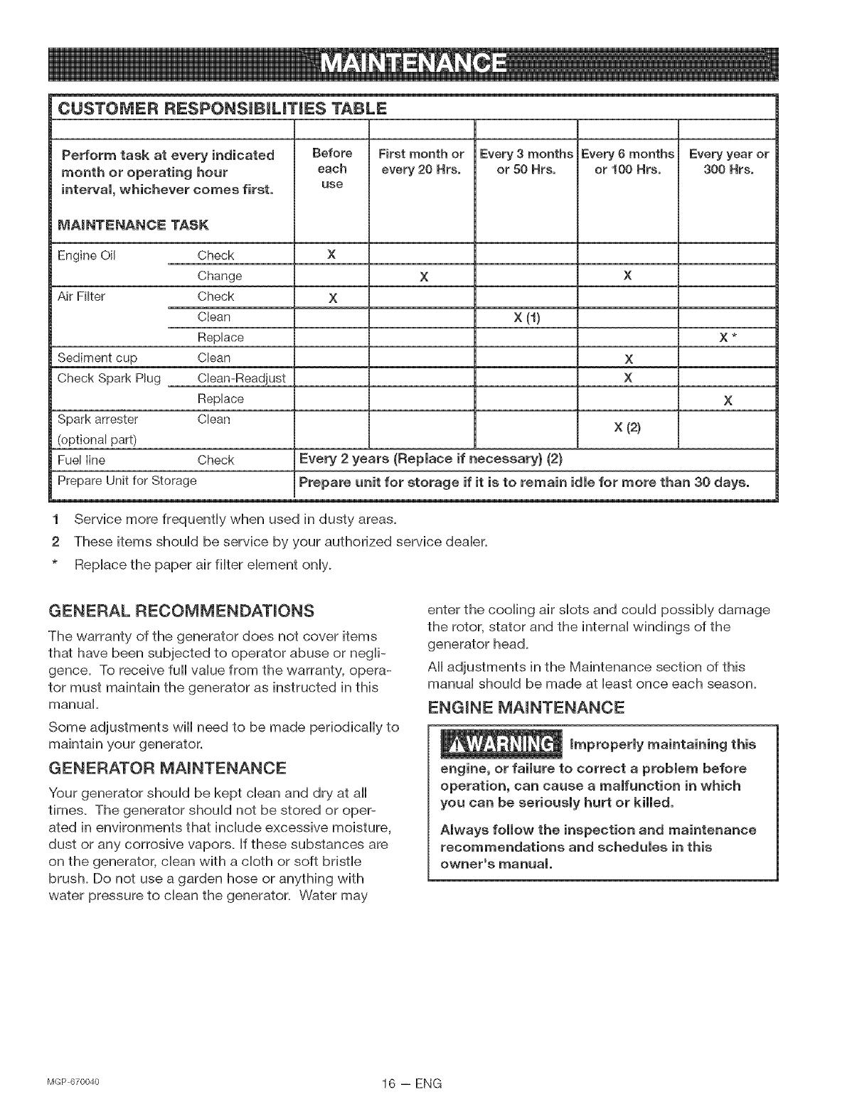
CUSTOMER RESPONSRBRLRTRES TABLE
Perform task at every indicated
month or operating hour
interval, whichever comes first.
MAINTENANCE TASK
Engine Oil
Air Filter
Sediment cup
Check Spark Plug
Check
Change
Check
Clean
Replace
Clean
Cban-Readjust
Replace
Clean
Before
each
use
Every 3 months
or 50 Hrs,
Every 6 months
or t00 Hrs,
X
X
First month or
every 20 Hrs°
x (9
X
X
Every year or
300 Hrs,
X _
X
Spark arrester X (2)
(optional part)
Fuel line Check Every 2 years (Replace if necessary} (2}
Prepare Unit for Storage Prepare unit for storage if it is to remain idle for more than 30 days.
1 Service more frequently when used in dusty areas.
2 These items should be service by your authorized service dealer.
* Replace the paper air filter element only.
GENERAL RECOMMENDATIONS
The warranty of the generator does not cover items
that have been subjected to operator abuse or negli-
gence. To receive fuji value from the warranty, opera-
tor must maintain the generator as instructed in this
manual.
Some adjustments wiii need to be made periodicaiiy to
maintain your generator.
GENERATOR MAmNTENANCE
Your generator should be kept clean and dry at all
times. The generator should not be stored or oper-
ated in environments that include excessive moisture,
dust or any corrosive vapors. If these substances are
on the generator, clean with a cloth or soft bristle
brush. Do not use a garden hose or anything with
water pressure to clean the generator. W/ater may
enter the cooling air slots and could possibly damage
the rotor, stator and the internal windings of the
generator head.
All adjustments in the Maintenance section of this
manual should be made at least once each season.
ENGmNE MAmNTENANCE
Improperly maintaining this
engine, or failure to correct a problem before
operation, can cause a malfunction in which
you can be seriously hurt or killed,
Amways fommow the inspection and maintenance
recommendations and schedumes in this
owner's manual
MGP670040 16 -- ENG
Oil
Oii bvei shouid be checked prior to each use and
at bast every 5 hours of operation.
To check oil:
Remove the filler cap/dipstick and wipe it clean.
Insert and remove the dipstick without screwing it
into the filler neck. Check the oil level shown on
the dipstick,
If the oil level is low, fiii to the edge of the oil filler
hob with the recommended oil. See the Adding
Oil paragraph on page 14 of this manual.
Screw in the filler cap/dipstick securely.
Filler Cap/Dipstick
edge of the oil filler hob with the recommended
oil. See the Adding Oil paragraph on page 14 of
this manual.
Air Filter
A dirty air filter wiii restrict air flow to the carburetor,
reducing engine performance. If you operate the
engine in very dusty areas, clean the air filter more
often than specified in the Owner's Responsibilities
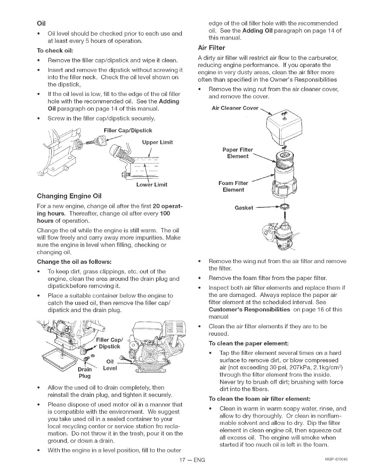
Remove the wing nut from the air cleaner cover,
and remove the cover.
Air Cleaner Cover
Foam Fimter
Element
Changing Engine Oil
For a new engine, change oil after the first 20 operat=
ing hours. Thereafter, change oil after every 100
hours of operation.
Gasket
Change the oil while the engine is still warm. The oil
wiii flow freely and carry away more impurities. Make
sure the engine is level when filling, checking or
changing oil.
Change the oil as follows:
To keep dirt, grass ciippings, etc. out of the
engine, clean the area around the drain piug and
dipstbkbefore removing it.
Piace a suitaMe container bellow the engine to
catch the used oii, then remove the filler cap/
dipstick and the drain piug.
Remove the wing nut from the air filter and remove
the filter.
@
@
Remove the foam filter from the paper filter.
Inspect both air filter elements and replace them if
the are damaged. Always replace the paper air
filter element at the scheduled interval See
Customer's Responsibilities on page 16 of this
manual
Allow the used oil to drain completely, then
reinstall the drain plug, and tighten it securely.
Please dispose of used motor oil in a manner that
is compatible with the environmenL We suggest
you take used oil in a sealed container to your
local recycling center or service station fro recla-
mation. Do not throw it in the trash, pour it on the
ground, or down a drain.
With the engine in a level position, fill to the outer
Clean the air filter elements if they are to be
reused.
clean the paper element:
Tap the filter element several times on a hard
surface to remove dirt, or blow compressed
air (not exceeding 30 psi, 207kPa, 2_1kg/cm 2)
through the filter element from the inside.
Never try to brush off dirt; brushing with force
dirt into the fibers.
To clean the foam air filter element:
Clean in warm in warm soapy water, rinse, and
allow to dry thoroughly. Or clean in nonflam-
mable solvent and allow to dry. Dip the filter
element in clean engine oil, then squeeze out
aii excess oil. The engine wiii smoke when
started if too much oil is left in the foam.
17 -- ENG
MGP 670040
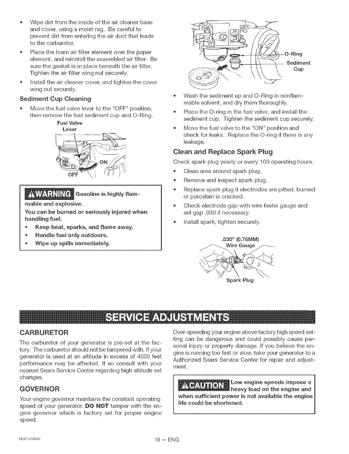
Wipe dirt from the inside of the air cbaner base
and cover, using a moist rag. Be carefui to
prevent dirt from entering the air duct that Heads
to the carburetor.
Hace the foam air fiiter ebment over the paper
ebment, and reinstall the assembbd air fiiter. Be
sure the gasket is in piace beneath the air fiiter.
Tighten the air fiiter wing nut secureiy.
Install the air cleaner cover, and tighten the cover
wing nut secureiy.
Sediment Cup Cleaning
Move the fuei vaive bver to the "OFF" position,
then remove the fuei sediment cup and O-Ring.
rue[ VaJve
Lever
Gasoline is highly flam-
mable and explosive,
You can be burned or seriousJy injured when
o Keep heat, sparks, and flame away,
HandJe fuel onJy outdoors,
, Wipe up spills immediately,
Wash the sediment up and O-Ring in nonflam-
mable solvent, and dry them thoroughly.
Place the O-ring in the fuel valve, and install the
sediment cup. Tighten the sediment cup securely.
Move the fuel valve to the "ON" position and
check for leaks. Replace the O-ring if there is any
leakage.
Clean and RepJace Spark PJug
Check spark plug yearly or every 100 operating hours.
Clean area around spark plug.
Remove and inspect spark plug.
Replace spark plug if electrodes are pitted, burned
or porcelain is cracked.
Check electrode gap with wire feeler gauge and
set gap .030 if necessary.
Install spark, tighten securely.
Spark Pmug
CARBURETOR
The carburetor of your generator is pre-set at the fac-
tory. The carburetor should not be tampered with. [f your
generator is used at an altitude in excess of 4000 feet
performance may be affected. If so consult with your
nearest Sears Service Center regarding high altitude set
changes.
GOVERNOR
Your engine governor maintains the constant operating
speed of your generator. DO @OT tamper with the en-
gine governor which is factory set for proper engine
speed.
Over-speeding your engine above factory high speed set-
ting can be dangerous and could possibly cause per-
sonai injury or property damage. If you believe the en-
gine is running too fast or slow, take your generator to a
Authorized Sears Service Center for repair and adjust-
ment.
MGP670040 18 -- ENG
If you are going to store your generator for more than
30 days, use the foiiowing information as a guide to
prepare the generator for storage.
Never store generator with
in the tank indoors or in
encmosed, poormy ventimated areas, where fumes
can reach an open fmame, spark or pimot mightas
on a furnace, water heater, cmothes dryer or
other gas appmiances°
Engine Preparation
* Add fuel stabilizer to fuel tank to minimize the
formation of fuel gum deposits during storage.
Run engine at bast 10 minutes after adding
stabilizer to allow it to enter the fuel system.
Disconnect the spark plug wire and remove the
spark plug.
Add one teaspoon of oil through the spark plug
hob.
Place rag over spark plug hob and pull the recoil a
few times to lubricate the combustion chamber.
Replace the spark plug, but do not connect the
spark plug wire.
NOTE: If a fuel stabilizer is not used, all gasoline must
be drained from the tank and carburetor to prevent gum
deposits from forming on these parts and causing pos-
sible malfunction of the engine.
Generator
Clean the generator as outlined in the Generator
Maintenance paragraph on page 16
Check that cooling air dots and openings on
generator are open and unobstructed.
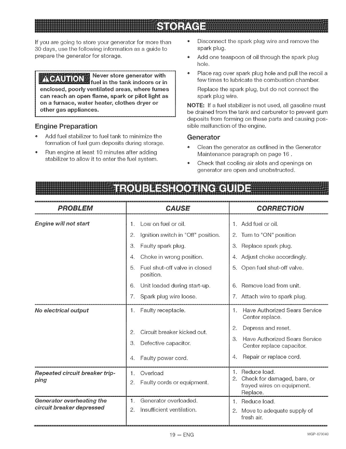
Engine will not start
No electrical output
Repeated circuit breaker trip-
ping
Generator overheating the
circuit breaker depressed
1. Low on fuel or oil.
2. Ignition switch in "Off" position.
3. Faulty spark plug.
4. Choke in wrong position.
5. Fuel shut-off valve in closed
position.
6. Unit loaded during start-up.
7. Spark plug wire loose.
1. Faulty receptacle.
2. Circuit breaker kicked out.
3. Defective capacitor.
4. Faulty power cord.
1. Overload
2. Faulty cords or equipment.
1. Generator overloaded.
2. Insufficient ventilation.
CORRECTION
1. Add fuel or oil.
2. Turn to "ON" position
3. Replace spark plug.
4. Adjust chokeaccordingiy.
5. Open fuel shut-off valve.
6. Remove load from unit.
7. Attach wire to spark plug.
1. Have Authorized Sears Service
Center replace.
2. Depress and reset.
3. Have Authorized Sears Service
Center replace capacitor.
4. Repair or replace cord.
1. Reduce ioad.
2_ Check for damaged, bare, or
frayed wires on equipmenL
Repiace.
1. Reduce ioad.
2. Move to adequate supply of
fresh air.
19 - ENG lvlGp670040

CRAFTSMAN 4250 GENERATOR 9t 9=670040 GENERATOR ASSEMBLY
5_
6
2 j
TORQUE 60-70 IN-LBS
4
\
\
\
\
\
TORQUE 20-25 IN-LBS
......9
8
2O
9 TORQUE 60-70 IN-LBS
14
TORQUE 96-120 IN-LBS
11/ / / _13
TORQUE 120-144 IN-LBS 10
12
TORQUE 96-120 IN-LBS
KEY
NO, DESCRIPTION
1 FUEL TANK
2 FUEL TANK SCREWS
3 WASHER
4 FUEL CAP
5 FRAME ASSEMBLY
6 PANELASSEMBLY
7 ISOLATOR
8 FUEL NOSE
9 HEATSHELD
10 ISOLATOR
11 LOCK NUT 5/16-18
12 SCREW 5/16=18 x 1
13 LOCK WASNER
14 SCREW 5/16=18 x 3/4
15 GROUND STRAP
16 ENGINE (modeJ # GX270VWN2)
17 NOSE CLAMP .301 ID
18 UNION REDUCER 1/4 TO 3/8
19 SCREW 1/4 x 5/8
20 LOCK WASHER
* SEE ENGINE PAGES 27-36
PART NUMBER
GS=0795
91895680
SSN-632
GS=0443
GS=0909
GS-0844
GS-0433
GS=0225
GS=0675
GS=0033
SSF=8150
SSF=605
SSN-1619=ZN
SS=12=CD
GS-0118
GS-0560
GS-0535
39124607
SS-1503=CD
MGP67OO4O 20 -- ENG
/