
Installation Instructions
....'' ....... E e "trh:
Instructions d'installation
; o ............... . ..
Instrucciones para la instalaci6n
f
I
\
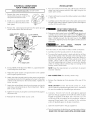
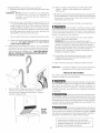
simplify the installation and ensure the laundry center is installed correctly
and safely. Leave these instructions near the laundry center after installation
for future reference.
NOTE; The electrical service to the laundry center must conform with local
codes and ordinances and the latest edition of the National Electrical Code,
ANSI/NFPA 70, or in Canada, the Canadian Electrical Code, CSA C22.1
NOTE: The gas service to the laundry center must conform with local codes
and ordinances and the latest edition of the National Fuel Gas Code AN_I
Z223. 1/NFPA 54, or in Canada, the Canadian Natural Gas and Propane
Installation Code, CSA B149. 1.
NOTE: The laundry center is designed under ANSI Z21.5.1 or ANSI/UL
2158- CAN/CSA C22.2 No. 112 (latest edition) for HOME USE only. This
laundry center is not recommended for commercial applications such as
restaurants or beauty salons, etc.
Avant de commencer, lireattentivement le present document. Cela simplifiera
I'installation et assurera la posecorrecte et securitaire de la secheuse. Apres
I'installation, laisser ce document a proximite de la secheuse pour reference
future.
REM, a,ROUE "L'alim entation electriq ue de la secheuse doit respecter lescodes
et ordonnances Iocaux ainsi que I'edition la plus recente du CodeANSVNFPA 70,
ou au Canada, le Code canadien d'elect ricite, ACNOR C22.1, partiel.
REM, a,ROUE : L'alimentation en gaz de la secheuse doit respecter les codes
et ordonnances Iocaux ainsi que I'edition laplus recente du Code ANSI Z223.1,
ou au Canada, le code CAN/AC G B149.12.
RE_,a, RO UE - Lasecbeuse est concue conformement au code ANSI Z 21.5.1
ou ANSI/UL 2158- CAN/AC G C22.2 No. 112 (l'edition la plus recente) pour un
USAGE DOMESTIQUE seulement. Cette secheuse n'est pas recommandee
pour utilisation commerciale, comme par exemple un restaurant ou un salon
de coiffure, etc. ........
r r r r
Antes decomenzar lainstalaci6n, lea cuidadosamente estasinstrucciones. Esto
simplificar_la instalaci6n yasegurara que la secadora seinstale correctamente
y de manera segura. Despu6s de completar la instalacion, coloque estas
instrucciones cerca de la secadora para referenda futura.
NOTA: Laalimentacion eK_drica para lasecadora deber_i cumplir con losc6digos
y reglamentos localesycon la 01timaedici0n del C6digo Electrico Nacional, ANSI/
NFPA70 o en Canada1CSAC22.1 C6digo EI6ctdco Canadiense, Parte I.
NOTA: Laalimentaci6n degas para la secadora deber_ cumplir con los codigos
y regla mentos locales y con la 0kima edici6n del C6digo Nacional para Gases
Combustibles, ANSIZ223.1 o en Canada CAN/CGA B149.12.
NOTA: La secadora esta dasificada para USO DOMESTICO solamente, de
acuerdo con la norma ANSI Z21.5.1 oANSI/UL 2158- CAN/CSA C22.2 No. 112
(las 0kimas edici6nes). Estasecadora no se recomienda para uso commercial
tal como en restaurantes, salones de belleza, etc.
iii
11 (_1 1 [ [(}[
Printed in U.S.A. P/N134809200 (0610)

Contents
SUBJECT PAGE
Pre-lnstallation Requirements .......................................... 2
Electrical Requirements ................................................... 2
Water Supply Requirements ........................................... 2
Drain Requirements .......................................................... 2
Exhaust System Requirements ...................................... 2-3
Gas Supply Requirements ................................................ 3
Location ............................................................................ 3
Mobile Home Installation .................................................. 3
Rough-In Dimensions ......................................................... 4
Unpacking ......................................................................... 4
Electrical Installation ......................................................... 5
Grounding Requirements .................................................. 5
3 & 4-Wire Connections ................................................. 5-6
installation ..................................................................... 6-7
Replacement Parts ........................................................... 7
PRE-INSTALLATION REQUIREMENTS
Tools and Materials Required for Installation:
1. Phillips head screwdriver.
2. Channel-lock adjustable pliers.
3. Carpenter's level.
4. Flat or straight blade screwdriver.
5. Duct tape.
6. Rigid or flexible metal 4 inch (10.16 cm) duct.
7. Vent hood.
8. Pipe thread sealer (Gas).
9. Ratchet with 3/8 inch (0.96 cm) socket.
For your safety the information in this manual must be
followed to minimize the risk of fire or explosion or to prevent property
damage, personal injury or loss of life.
- Do not store or use gasoline or other flammable vapors and
liquid in the vicinity of this or any other appliance.
- WHAT TO DO IF YOU SMELL GAS
• Do not try to light any appliance.
. Do not touch any electrical switch; do not use any phone in your
buikJing.
• Clear the room, building or area of all occupants.
Immediately call your gas supplier from a neighbor_ phone.
• Follow the gas supplier's instructions.
• If you cannot reach your gas supplier, call the fire department.
Installation and service must be preformed by a qualified installer, service
agency or the gas supplier.
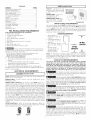
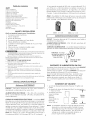
ELECTRICAL REQUIREMENTS
[ ELECrR/CLaundry Center ]
Circuit- Individual 30 amp branch circuit fused with 30 amp minimum time
delay fuses or circuit breakers.
POWER SUPPLY - 3-wire or 4-wire , 240 volt, single phase, 60 Hz,
Alternating Current.
POWER SUPPLY CORD KIT- The laundry center MUST employ a 3-
condutor power supply cord NEMA 10-30 type SRDT rated at 240 volt AC
minimum, 30 amp, with 3 open end spade lug connectors with upturned
ends or closed loop connector OR a 4-condutor power supply cord NEMA
14-30 type SRDT or ST (as required) rated at 240 volt AC minimum, 30
amp, with 4 open end spade lug connectors with upturned ends or closed
loop connectors and marked for use with clothes dryers, if being installed
in a new branch circuit installation, manufactured (mobile) home, recreational
vehicle or area which prohibits grounding through the neutral conductor,
the laundry center MUST employ a 4-condutor power supply cord NEMA
14- 30 type SRDT or ST (as required) rated at 240 volt AC minimum, 30
amp, with 4 open end spade lug connectors with upturned ends or closed
loop connectors and marked for use with clothes dryers. See ELECTRICAL
CONNECTIONS. (Canada - 4-wire power supply cord is installed on laundry
center.)
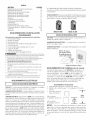
OUTLET RECEPTACLE- NEMA 10-30R (3-wire) receptacle or NEMA 14-
30R (4-wire) receptacle to be located so the power supply cord is accessible
when the laundry center is in an installed position.
NEMA NEMA
I GASLaundry Center ]
CIRCUIT- Individual 15 amp
minimum branch circuit fused with NOTE:Donot under
anycircumstances
a time delay fuse or circuit reroovegrounding
breaker. prongfromplug.
POWER SUPPLY -3 wire, 120
volt single phase, 60 Hz,
Alternating Current.
POWER SUPPLY CORD -The
gas laundry center is equipped
with a 120 volt 3-wire power
cord. GroundingProng
WATER SUPPLY REQUIREMENTS
Hot and cold water faucets MUST be installed within 42 inches (106.68
cm) of your laundry center's water inlet. The faucets MUST be 3/4 inch
(1.9 cm) garden hose type so inlet hoses can be connected. Water
pressure MUSTbe between 10 and 120 pounds per square inch (maximum
unbalance pressure, hot vs. cold, 10 psi). Your water department can
advise you of your water pressure.
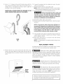
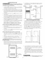
DRAIN REQUIREMENTS
1. Drain capable of
eliminating 17 gaB. per
minute.
2. A standpipe diameter of
I_A inches (3.18 cm)
minimum.
3. The standpipe height
above the floor should
be:
Minimum height:
33 inches (83.82 cm)
Maximum height:
96 inches (244 cm)
33" Min.
(83.82cm)
1'
96"Max.
(244 cm)
NOTE: For installations requiring a longer drain hose, have a qualified
technician install a longer hose, PIN 134049201, available from an authorized
parts distributor. For drain systems in the floor, install a siphon break kit,
available from your local hardware store .
EXHAUST SYSTEM REQUIREMENTS
Use only 4 inch (10.16 cm) diameter (minimum) Hqid or flexible
metal duct and approved vent hood which has a swing-out
damper(s) that opens when the dryer is in operation. When the
dryer stops, the damper(s) automatically closes to prevent drafts
and the entrance of insects and rodents. To avoid restricting the
outlet, maintain a minimum of 12 inches (38.5 cm) clearance
between the vent hood and the ground or any other obstruction.
_The following are specific requirements for proper and
safe operation of your laundry center. Failure to follow these instructions
can create excessive drying times and fire hazards.
Do not use plastic flexible duct or metal foil to exhaust
the dryer. Excessive lint can build up inside the exhaust system and create
a fire hazard and restrict air flow. Restricted air flow will increase drying
times. If your present system is made up of plastic duct or metal foil duct,
_lace it with a rigid or flexible metal duct. Ensure the present duct is
free of any lint prior to installing laundry center dryer duct.
_lf the dryer is not exhausted outdoors some fine lint will
be expelled into the laundry area. An accumulation of lint in any area of
the home can create a health and fire hazard. The dryer exhaust system
MUST be exhausted to the outside of the dwelling!
Do not allow combustible materials (for example:
dothinq,draperies/curtains, paper) to come in contact with the exhaust
_stem. The dryer MUST NOT be exhausted into a chimney, a wall, a
ceiling, or any concealed space of a building which can accumulate lint,
resulting in a fire hazard.
Do not exceed the length of duct pipe or number of
elbows allowed in the" EXHAUST DUCT LENGTHS" chart. Lint can
accumulate in the system, plugging the system and creating a fire hazard,
as well as increasing drying times.
_Do not screen the exhaust ends of the vent system nor
use any screws or rivets to assemble the exhaust system. Lint can
become caught in the screen, on the screws or rivets, clogging the
exhaust system and creating a fire hazard as well as increasing drying
times. Use an approved vent hood to terminate the duct outdoors, and
seal all joints with duct tape. All male duct pipe fittings MUST be installed
downstream with the flow of air.

Explosion hazard. Do not install the laundry center
where gasoline or other flammables are kept or stored.if the laundry
center is installed in a garage, it must be a minimum of 18 inches (45.7 cm)
above the floor. Failure to do so can result in death, explosion, fire or burns.
The exhaust system back pressure MUST not exceed 0.6 inches (1.52 cm)
of water column, measured with an inclined manometer at the point the
exhaust connects to the dryer. The exhaust system should be inspected
and cleaned a minimum of every two years with normal usage. The more
the dryer is used, the more often you should check the exhaust system
and vent hood for proper operation.
The maximum length of the exhaust system depends upon the type of
duct used, number of elbows and type of exhaust hood.
The maximum length for both rigid and flexible duct is shown in the chart
below.
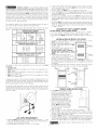
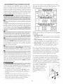
EXHAUST DUCT LENGTHS
EXHAUST HOOD TYPE
Number
Turns _
4_ 4_
(102 CM) Louvered (635 CM)
MAXIMUM LENGTH OF 4-INCH (10.2 CM)
DIAMETER RIGID METAL DUCT
0
1
2
3
56 ft. (17.07 m) 42 ft. (12.8 m)
46 ft. (14.02 m) 36 ft. (10.97 m)
34 ft. (10.36 m) 28 ft. (8.53 m)
32 ft. (9.75 m) 18 ft. (5.48 m)
MAXIMUM LENGTH OF 4-INCH (10.2 CM)
DIAMETER FLEXIBLE METAL DUCT
0
1
2
3
30 ft. (9.14 m) 22 ft. (6.7 m)
22 ft. (6.7 m) 14 ft. (4.27 m)
16 ft. (4.88 m) 10 ft. (3.05 m)
10 ft. (3.05 m) 5 ft. (1.5 m)
The laundry center may be exhausted four (4) ways with rear flush
installation:
1. Straight back
2. Down (8 inch [20.32 cm] length of 4 inch [10.16 cm] rigid duct and 1
elbow down)
3. Left (8 inch [20.32 cm] length of 4 inch [10.16 cm] rigid duct, 1 elbow
down and 1 elbow left)
4. Right(8 inch [20.32 cm] length of 4 inch [10.16 cm] rigid duct, 1 elbow
down and 1 elbow right)
To exhaust up, add an 11 inch (27.94 cm) length of standard 4 inch (10.16
cm) diameter duct and a 90° elbow. The unit will be positioned about 4Y2
inches (11.43 cm) away from the wall (flush to wall exhausting may be
done by going below the dryer then sideways).
An exhaust hood positioned to line up with the dryer exhaust can be
installed directly through the outside wall. To exhaust to the side or down,
add an 8 inch (20.32 cm) length of standard 4 inch (10.16 cm) diameter duct
and a 90° elbow.
GASSUPPLYREQUIREMENTS
1. Installation MUST conform with local codes, or in the absence of local
codes, with the National Fuel Gas Code, ANSI Z223.1 (latest edition) or
in Canada, the current AN/CGA B149.
2. The gas supply line should be of 1/2 inch (1.27 cm) pipe.
3
3. If codes allow, flexible metal tubing may be used to connect your dryer
to the gas supply line. The tubing MUST be constructed of stainless
steel or plastic-coated brass.
4. The gas supply line MUST have an individual shutoff valve.
5. A 1/8 inch (0.32 cm) N. R T. plugged tapping, accessible for test gage
connection, MUST be installed immediately upstream of the gas supply
connection to the dryer.
6. The dryer and its individual shutoff valve MUST be disconnected from
the gas supply piping system during any pressure testing of the gas
supply piping system at test pressures equal to or less than 1/2 psig
(3.45 kPa).
7. The dryer MUST be isolated from the gas supply piping system by
closing its individual manual shutoff valve during any pressure testing
of the gas supply piping system at test pressures equal to or less than
1/2 psig (3.45 kPa).
LOCATION OF YOUR LAUNDRY CENTER
DO NOT INSTALL YOUR LAUNDRY CENTER:
1. In an area exposed to dripping water or outside weather conditions.
2. In an area where it will come in contact with curtains or drapes.
3. On carpet. Floor MUSTbe solid with a maximum slope of 1 inch (2.54
cm).
1.
2.
3.
4.
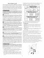
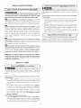
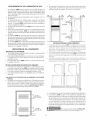
INSTALLATION IN RECESS OR CLOSET
A laundry center installed in a bedroom bathroom, recess or closet,
MUST be exhausted outdoors. .............................................
...... /
No other fuel burning appliance shall be _rl_ ]
installed in the same closet as the Gas I _0so._..
laundry center. !_!7.1SO.CMI
Your laundry center needs the space
around it for proper ventilation. I[ll
DO NOT INSTALL YOUR LAUNDRY
CENTER IN A CLOSET WITH A SOLID
DOOR. _" I1: 3_ 60 SO. IN.
A minimum of 120 square inches ))' 1_87_soCM)
(774.2 square cm) of opening, equally _L
divided at the top and bottom of
the door, is required. Air openings Coset Doo)"
are required to be unobstructed when a door is installed. A Iouvered
door with equivalent air openings for the full length of the door is
acceptable.
The following illustrations show minimum clearance dimensions and air
openings for proper operation in a recess or closet installation.
MOBILE HOME INSTALLATION
Dryer MUST be exhausted outside
(outdoors, not beneath the mobile
home) using metal ductinq that will
not support combustion. _letal
ducting must be 4 inches (10.16 cm)
in diameter with no obstructions.
Rigid metal duct is preferred.
If dryer is exhausted through the
floor and area beneath the mobile
home is enclosed, the exhaust
system MUST terminate outside
the enclosure with the termination
securely fastened to the mobile
home structure. 7
3. Refer to page 3 for other important venting requirements.
4. When installing a gas dryer into a mobile home, a provision must be
made for outside make up air. This provision is to be not less than twice
the area of the dryer exhaust outlet.
5. Installation MUST conform to current Manufactured Home Construction
& Safety Standard (which is a Federal Regulation Title 24 CFR-Part 32-
80) or when such standard is not applicable, with American National
Standard for Mobile Homes. in Canada, the CSA Z240 is applicable.
I_'!_giT/:11|lllllel The laundry center is designed under ANSI Z 21.5.1 for
HOME USE only.

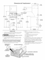
75YzIN,
(191.77 CM)
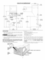
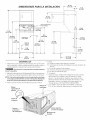
ROUGH-IN DIMENSIONS
54 5/16 IN.
(137.95 CM)
CONNECTION ©
WATERINLETS _ --
43 IN.
(109.22 CM)
(REAR)
._ DRAIN OUTLET
(REAR)
_J
3%1N.
_(9.52 CM)
27IN.
(68.58CM)
16¼ IN.
(41.27 CM)
_GAS SUPPLY
PIPE(REAR)
5 I/4 IN, _
_(13.33 CM) /
43 IN.
11::
I (104.77CM)
29 7/16 IN
(74.77CM)
25 ¼ IN.
(64.13 CM) --
47" --
\
36 1/161N.
(91.60 CM)
II
30 13/16 IN.
(78.26 CM)
2 YzIN.
(6.35 CM)
17/8 IN.
(4.76CM)
4 13/16 IN.
(12.22CM)
+
117/16 IN.
(29.5 CM)
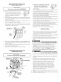
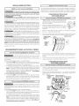
UNPACKING
1. Using the four shipping carton corner posts (two on each
side), carefully lay the laundry center on its left side and
remove foam shipping base.
Excessive weight. Use two or more people
to move Laundry Center.
2. Using a ratchet with 3/8 inch (0.96 cm) socket, remove the
mechanism shipping bolt and plastic spacer block from the
center of the base.
NOTE: If the laundry center isto be transported at a later
date, the tub blocking pad, shipping bolt, and plastic
spacer block should be retained.
3. Return laundry center to an upright position.
PLASTIC SPAC ER
4. Remove:
(a) foam tub blocking pad.
(b) foam shipping blocks from rear of unit.
(c) tape from dryer door.
(d) foam dryer support pads.
(e) inlet hoses.
(f) enclosure package.
5. From the back of the washer, remove the wire shipping
clips securing the drain hose and power cord (if equipped).
Plastic clamps secure the drain hose to the right side of
the washer backsheet. These clamps form a standpipe to
prevent water syphoning. DO NOT REMOVE THESE
CLAMPS.
.
Carefully move the laundry center to within 4 feet (1.22 m)
of the final location to begin the installation.
MECHANIS
SHIPPING
BOLT
POSTS
FOAM
SHIPPING
PAD
(IF EQUIPPED)
DRAIN HOSE

ELECTRICAL INSTALLATION
i ALL ELECTRICLaundry Centers ]
The following are specific requirements for
proper and safe electrical installation of your laundry center.
Failure to follow these instructions can create electrical shock
and/or a fire hazard.
This appliance MUST be properly grounded.
Electrical shock can result if the laundry center isnot properly
grounded. Follow the instructions in this manual for proper
grounding.
Do not use an extension cord with this
laundry center. Some extension cords are not designed to
withstand the amounts of electrical current this laundry center
utilizes and can melt, creating electrical shock and/or fire hazard.
Locate the laundry center within reach of the receptacle for the
length power cord to be purchased, allowing some slack in the
cord. Refer to the pre-installation requirements in this manual
for the proper power cord to be purchased.
A U.L approved strain relief must be installed
onto power cord. If the strain relief isnot attached, the cord can
be pulled out of the laundry center and can be cut by any
movement of the cord, resulting in electrical shock.
Do not use an aluminum wired receptacle i
with a copper Wired power cord and plug (or vice versa). A
chemical reaction occurs between copper and aluminum and
can cause electrical shorts. The proper wiring and receptacle 1.
is a copper wired power cord with a copper wired
receptacle OR aluminum wired power cord with an
aluminum wired receptacle. 2.
NOTE: Laundry centers operating on a 208 volt power supply
will have longer drying times than laundry centers operating on
a 240 volt power supply.
GROUNDING REQUIREMENTS
[ Non-CanadianELECTRlCLaundryCenter ]
Improper connection of the equipment
grounding conductor can result in a risk of electrical shock.
Check with a licensed electrician ifyou are in doubt asto whether
the appliance isproperly grounded.
For a qrounded, cord-connected laundry center:
1. The laundry center MUST be grounded. In the event of
malfunction or breakdown, grounding will reduce the risk of
electrical shock by a path of least resistance for electrical
current.
2. If your laundry center isequipped with a power supply cord
having an equipment-grounding conductor and agrounding
plug, the plug MUSTbe plugged into anappropriate, copper
wired receptacle that is properly installed and grounded in
accordance with all local codes and ordinances. If in doubt,
call a licensed electrician. Do not modify plug provided
with the appliance.
For a permanently connected laundry center:
The laundry center MUST be connected to a grounded metal,
permanent wiring system; or an equipment grounding conductor
MUST be run with the circuit conductors and connected to the
equipment-grounding terminal or lead on the appliance.
I Canadian ELECTRICLaundry Center j
_lmproper connection of the equipment
grounding conductor can result in a risk of electrical shock.
Check with a licensed electrician if you are in doubt as to
whether the appliance is properly grounded.
Foragrounded cord connected laundry center:
1. The laundry center MUST be grounded. In the event of
malfunction or breakdown, grounding will reduce the risk of
electrical shock by providing a path of least resistance for
the electrical current.
2. Since your laundry center is equipped with a power supply
cord having an equipment-grounding conductor and a
grounding plug, the plug MUST be plugged into an
appropriate outlet that isproperly installed and grounded in
accordance with all codes and ordinances. If in doubt, call
a licensed electrician.
ALL GAS Laundry Centers
1
1.The laundry center isequipped with a three-prong (grounding)
plug for your protection against shock hazard and should
be plugged directly into a properly grounded three-prong
receptacle. Do not cut or remove the grounding prong from
the plug.
.
4.
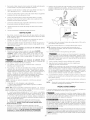
ELECTRICAL CONNECTIONS
FOR A 3-WIRE SYSTEM
NON-CANAD/AN ELECTR/CLaundry Center j
Remove the screw securing the
terminal block access cover to
the rear panel and remove cover.
Install a U.L approved strain
relief connector in the entry
hole on the back panel.
Insert a NEMA 10-30 Type SRDT,
U.L approved power cord through the strain relief.
Attach the power cord neutral (central wire) conductor to
the silver colored center terminal on the terminal block.
Tighten the screw securely.
GREEN GROUND SCREW
SILVER TERMINAL
NEUTRAL
GROUND
WIRE
5. Attach the remaining two power cord outer conductors to
the outer brasscolored terminals on the terminal block.
Tighten both screws securely.
6. Tighten the screws securing the cord restraint against the
power cord.
7. Reinstall the terminal access cover.

ELECTRICAL CONNECTIONS
FOR A 4-WIRE SYSTEM
NON-CANADIAN ELECTRICLaundry Center
1. Remove the screw securing the
terminal block access cover to the
rear panel and remove cover.
2. Install a U.L approved strain relief
connector in the entry hole on the
back panel.
]
INSTALLATION
Run some water from the hot and cold faucets to flush the
water lines and remove particles that might clog up the
water valve screens.
.
3.
Check inlet hoses to ensure the rubber washers are installed
in each end.
Carefully connect the inlet hoses to the water valve (on the
left side of the washer cabinet), tighten byhand, then tighten
another 2/3 turn with pliers.
3. Remove the neutral ground wire from the green ground
screw located above the termial block.
4. Insert a NEMA 14-30 TypeSTor SRDT,U.L approved power
cord through the strain relief.
DO NOT CROSS THREAD OR
OVERTIGHTEN THESE CONNECTIONS.
4. Determine which water faucet isthe HOTwater faucet and
carefully connect the bottom inlet hose to the HOTwater
faucet, tighten by hand, then tighten another 2/3 turn with
pliers. Carefully connect the top inlet hose to the COLD
water faucet, tighten by hand, then tighten another 2/3 turn
with pliers.
DO NOT CROSS THREAD OR
OVERTIGHTEN THESE CONNECTIONS.
Turn the water on and check for leaks at both connections.
.
6.
Carefully move the laundry center to its final location.
To ensure the laundry center is level and solid on all four
legs, tilt the laundry center forward so the rear legs are off
the ground. Gently set the laundry center back down to
allow the rear legs to self adjust. Placea level on top of the
washer. Check it side to side, then front to back. Screw
the front leveling legs up or down to ensure the laundry
center is resting solid on all four legs (no rocking of the
laundry center should exist).
NOTE: Keep the leg extension at a minimum to prevent
excessive vibration.
5. Attach the green power cord ground wire to the cabinet
with the green ground screw.
6. Attach the white (neutral) wire from the power cord and the
neutral ground wire from the appliance harnessto the silver
colored center terminal on the terminal block. Tighten the
screw securely.
7. GAS CONNECTION (Gas laundry centers only)
a. Remove the shipping cap from gas pipe at the rear of the
dryer.
7. Attach the red and black wires from the power cord to the
outer brass-colored terminals on the terminal block. Tighten
both screws securely.
8. Tighten the screws securing the cord restraint firmly against
the power cord.
9. Reinstall the terminal block access cover.
NOTE: DO NOT connect the laundry center to L.R gas
service without converting the gas valve. An LR conversion
kit must be installed by a qualified gas technician.
b.
Connect a 1/2 inch (1.27 cm) I.D. semi-rigid or approved
pipe from the gas supply line to the 3/8 inch (0.96 cm) pipe
located on the back of the dryer. Use a 1/2 inch (1.27 cm)
to 3/8 inch (0.96 cm) reducer for the connection. Apply an
approved thread sealer that is resistant to the corrosive
action of liquefied gases on all pipe connections.
c. Open the shutoff valve in the gas supply line.
d. Test all connections by brushing on a soapy water solution.
NEVER TEST FOR GAS LEAKS WITH AN OPEN FLAME.

8. Form a " U " shape on the end of the drain hose with the
hose pointed toward the drain. Place the formed end in a
laundry tub or a standpipe and secure with a cable tie
provided in the enclosure package.
WATER WILL SYPHON FROM THE WASHER IF THE
ABOVE INSTRUCTIONS ARE NOT FOLLOWED.
C_ble
Tie
9. Remove the two (2) screws securing the dryer front access
panel to the dryer cabinet. Lift the panel until the tabs can
be disengaged from the cabinet. Removethe panel and set
aside.
10. Connect the exhaust duct to outside duct work. Use duct
tape to seal all joints.
11. Plug the power cord into a grounded outlet.
NOTE: Check to ensure the power isoff at a circuit breaker/
fuse box before plugging the power cord into an outlet.
12. Turn on the power at a circuit breaker/fuse box.
_ Before operating the dryer, make sure
the dryer area is clear and free from combustible
materials, gasoline, and other flammable vapors. Also
see that nothing (suchasboxes, clothing, etc.) obstructs
the flow of combustion and ventilation air.
13. Reinstall the dryer front access panel.
14. Runthe washer and dryer though acycle. Check for proper
operation.
NOTE: On gas dryers, before the burner will light, it is
necessary for the gas line to be bled of air. If the burner
does not light within 45 seconds the first time the dryer
is turned on, the safety switch will shut the burner off.
If this happens, turn the timer to "OFF" and wait 5
minutes before making another attempt to light.
15. If your laundry center does not operate, please review the
"Avoid Service Checklist" located in your Owner's Guide
before calling for service.
16. Place these instructions in a location near the laundry
center for future reference.
NOTE: A wiring diagram is located behind the dryer front
access panel.
REPLACEMENT PARTS
If replacement parts are needed for your laundry center, contact
the source where you purchased your laundry center.
Destroy the carton, plastic bags, and metal
band after the laundry center isunpacked. Children might use
them for play. Cartons covered with rugs, bedspreads, or plastic
sheets can become airtight chambers causing suffocation.
Place all materials in a garbage container or make materials
inaccessible to children.
Access
Panel
Screws
Label all wires prior to disconnection when
servicing controls. Wiring errors can cause improper and
dangerous operation. Verify proper operation after servicing.
The instructions in this manual and all other
literature included with this laundry center are not meant to
cover every possible condition and situation that may occur.
Good safe practice and caution MUST be applied when
installing, operating and maintaining any appliance.
Maximum benefits and enjoyment are achieved when all
the Safety and Operating instructions are understood and
practiced asa routine with your laundry tasks.
Page is loading ...
Page is loading ...
Page is loading ...
Page is loading ...
Page is loading ...
Page is loading ...
Page is loading ...
Page is loading ...
Page is loading ...
Page is loading ...
Page is loading ...
Page is loading ...
Page is loading ...
-
 1
1
-
 2
2
-
 3
3
-
 4
4
-
 5
5
-
 6
6
-
 7
7
-
 8
8
-
 9
9
-
 10
10
-
 11
11
-
 12
12
-
 13
13
-
 14
14
-
 15
15
-
 16
16
-
 17
17
-
 18
18
-
 19
19
-
 20
20


Frigidaire GLGT1031FS0 Installation guide
- Type
- Installation guide
- This manual is also suitable for
Ask a question and I''ll find the answer in the document
Finding information in a document is now easier with AI
in other languages
Related papers
-
Frigidaire FLGB8200FS1 Installation guide
-
Frigidaire GLGH1642DS0 Installation guide
-
Universal/Multiflex (Frigidaire) GCET1031FS4 Installation guide
-
-
Frigidaire FLXG52RBSA Installation guide
-
Crosley GLGH1642FS2 Installation guide
-
-
-
Frigidaire FLXG52RBSA Installation guide
-
Frigidaire GLGT1031FS - 3 cu. Ft. Laundry Center User manual
Other documents
-
Kenmore 41797822700 Installation guide
-
Kenmore 41797912702 Installation guide
-
Sears 6418 - 5.7 cu. Ft. Coin Operated Electric Dryer User manual
-
White-Westinghouse SGR351HS1 Installation guide
-
Electrolux EIED2CAQSW00 Installation guide
-
-
Kenmore 41798702891 Installation guide
-
Kenmore 41761722510 Installation guide
-
-