Unbranded Controllers and Accessories Installation guide
- Type
- Installation guide
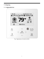
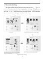
Unbranded Controllers and Accessories provide comprehensive control over your compatible HVAC system, allowing you to adjust settings, manage functions, and monitor the unit's status. With user-friendly button graphics and clear instructions, the controller offers easy navigation and setup. The device enables you to control various functions such as fan speed, swing direction, temperature, and operation modes, ensuring a customized and comfortable indoor environment. Additionally, it features a lock function to prevent unauthorized access to settings, providing an extra layer of security.
Unbranded Controllers and Accessories provide comprehensive control over your compatible HVAC system, allowing you to adjust settings, manage functions, and monitor the unit's status. With user-friendly button graphics and clear instructions, the controller offers easy navigation and setup. The device enables you to control various functions such as fan speed, swing direction, temperature, and operation modes, ensuring a customized and comfortable indoor environment. Additionally, it features a lock function to prevent unauthorized access to settings, providing an extra layer of security.


-
 1
1
-
 2
2
-
 3
3
-
 4
4
-
 5
5
-
 6
6
-
 7
7
-
 8
8
-
 9
9
-
 10
10
-
 11
11
-
 12
12
-
 13
13
-
 14
14
-
 15
15
-
 16
16
-
 17
17
-
 18
18
-
 19
19
-
 20
20
-
 21
21
-
 22
22
-
 23
23
-
 24
24
-
 25
25
-
 26
26
-
 27
27


Unbranded Controllers and Accessories Installation guide
- Type
- Installation guide
Unbranded Controllers and Accessories provide comprehensive control over your compatible HVAC system, allowing you to adjust settings, manage functions, and monitor the unit's status. With user-friendly button graphics and clear instructions, the controller offers easy navigation and setup. The device enables you to control various functions such as fan speed, swing direction, temperature, and operation modes, ensuring a customized and comfortable indoor environment. Additionally, it features a lock function to prevent unauthorized access to settings, providing an extra layer of security.
Ask a question and I''ll find the answer in the document
Finding information in a document is now easier with AI
Related papers
-
Gibson Controllers and Accessories Installation guide
-
Unbranded Wireless Remote Controller Installation guide
-
-
-
-
-
-
Other documents
-
Sinclair SWC-03 User manual
-
-
Sinclair MV-D09BI User manual
-
McQuay MQS-24030-CFC216A Operating instructions
-
mundoclima Series MUSTR-H3 “Ceiling Floor Full Inverter H3” Installation guide
-
MUND CLIMA Series MUCSR-H3 “Cassette Full Inverter H3” Owner's manual
-
Reznor B-HW**A3AK Installation guide
-
GREE Ducted XK60 Wired Controller User manual
-
Johnson Controls DWCR2 User manual
-