Page is loading ...

Dynamic Braking Resistors
AC & DC Motor Control
Instruction Manual
September 2020
Part Number: 140-10319 R8
© Copyright 2020 Magnetek

Dynamic Braking Resistors Instruction Manual
September 2020
2
U.S. Service Information
For questions regarding service or technical information contact:
1.866.MAG.SERV
(1.866.624.7378)
Field.service@magnetek.com
International Service
Outside the U.S. and Canada call 1.262.783.3500, press 3.
Headquarters
Columbus McKinnon Corporation
Magnetek Office
N49 W13650 Campbell Drive
Menomonee Falls, WI 53051
Telephone: 800.288.8178
Website: www.columbusmckinnon.com/magnetek
E-mail: mh.salesquotes@magnetek.com
Fax Numbers:
Main: 800.298.3503
Sales: 262.783.3510
Service: 262.783.3508
© 2020 MAGNETEK
All rights reserved. This notice applies to all copyrighted materials included with this product,
including, but not limited to, this manual and software embodied within the product. This manual is
intended for the sole use of the person(s) to whom it was provided, and any unauthorized
distribution of the manual or dispersal of its contents is strictly forbidden. This manual may not be
reproduced in whole or in part by any means whatsoever without the expressed written permission
of MAGNETEK.

Dynamic Braking Resistors Instruction Manual
September 2020
3
PRODUCT MANUAL SAFETY INFORMATION
Magnetek
®
offers a broad range of radio remote control products, control products and
variable frequency drives (VFD), and industrial braking systems for material handling
applications. This manual has been prepared by Magnetek to provide information and
recommendations for the installation, use, operation and service of Magnetek’s material
handling products and systems (Magnetek Products). Anyone who uses, operates,
maintains, services, installs, or owns Magnetek Products should know, understand, and
follow the instructions and safety recommendations in this manual for Magnetek Products.
The recommendations in this manual do not take precedence over any of the following
requirements relating to cranes, hoists lifting devices or other material handling equipment
which use or include Magnetek Products:
• Instructions, manuals, and safety warnings of the manufacturers of the equipment
where the radio system is used,
• Plant safety rules and procedures of the employers and the owners of facilities
where the Magnetek Products are being used,
• Regulations issued by the Occupational Health and Safety Administration (OSHA),
• Applicable local, state, or federal codes, ordinances, standards, and requirements,
or
• Safety standards and practices for the industries in which Magnetek Products are
used.
This manual does not include or address the specific instructions and safety warnings of
these manufacturers or any of the other requirements listed above. It is the responsibility
of the owners, users, and operators of the Magnetek Products to know, understand and
follow all of these requirements. It is the responsibility of the employer to make its
employees aware of all of the above listed requirements and to make certain that all
operators are properly trained. No one should use Magnetek Products prior to
becoming familiar with and being trained in these requirements and the instructions
and safety recommendations in this manual.

Dynamic Braking Resistors Instruction Manual
September 2020
4
WARNING, CAUTION, and NOTE Statements
WARNING, CAUTION, and NOTE statements are used throughout this manual to
emphasize important and critical information. You must read these statements to help
ensure safety and to prevent product damage. The statements are defined below.
NOTE: A note statement is used to notify people of installation, operation,
programming, or maintenance information that are important, but not hazard-
related.
WARNING
WARNING indicates a potentially hazardous situation which, if not avoided, could
result in serious injury or death.
CAUTION
CAUTION indicates a potentially hazardous situation, which, if not avoided, could
result in minor or moderate injury. It may also alert against unsafe practices.
WARNING
• This manual provides instructions on how to use Magnetek’s Dynamic Braking
Resistors. If you disregard the instructions, information, and/or warranty in the
manual, you could be assuming responsibility for damages, costs, or injury
incurred by such disregard.
• Do not touch any circuit components while the main AC or DC power is on.

Dynamic Braking Resistors Instruction Manual
September 2020
5
Table of Contents
Introduction ................................................................................................................................... 6
Installation ..................................................................................................................................... 7
CMAA Ratings ............................................................................................................................ 10
Specifications .............................................................................................................................. 12
230 Volt Traverse Motions – Mill Galvanized .......................................................................... 12
230 Volt Hoist Motions – Mill Galvanized ................................................................................ 13
460 Volt Traverse Motions – Mill Galvanized .......................................................................... 14
460 Volt Hoist Motions – Mill Galvanized ................................................................................ 15
575 Volt Traverse Motions – Mill Galvanized .......................................................................... 16
575 Volt Hoist Motions – Mill Galvanized ................................................................................ 17
230 Volt Traverse Motions - Weatherproof Louvered ............................................................. 18
230 Volt Hoist Motions – Weatherproof Louvered .................................................................. 19
460 Volt Traverse Motions - Weatherproof Louvered ............................................................. 20
460 Volt Hoist Motions – Weatherproof Louvered .................................................................. 21
575 Volt Traverse Motions – Weatherproof Louvered ............................................................ 22
575 Volt Hoist Motions – Weatherproof Louvered .................................................................. 23
Wiring .......................................................................................................................................... 24
Resistor Connection ................................................................................................................ 24
Thermostat Connection (Optional) .......................................................................................... 24
230 Volt Traverse Motions ...................................................................................................... 25
230 Volt Hoist Motions ............................................................................................................ 26
460 Volt Traverse Motions ...................................................................................................... 27
460 Volt Hoist Motions ............................................................................................................ 28
575 Volt Traverse Motions ...................................................................................................... 29
575 Volt Hoist Motions ............................................................................................................ 30
AC Dynamic Braking Resistor Dimensions ................................................................................. 31
Type S Enclosure .................................................................................................................... 31
Type W Enclosure ................................................................................................................... 32
Type A Enclosure .................................................................................................................... 33
Type B Enclosure .................................................................................................................... 34
Type P Panel-Mount ............................................................................................................... 35
DC Dynamic Braking Resistor Dimensions ................................................................................. 36
Type D Enclosure ................................................................................................................... 37
Type G Enclosure ................................................................................................................... 38

Dynamic Braking Resistors Instruction Manual
September 2020
6
Introduction
Magnetek Dynamic Braking Resistors consist of grid, smooth wound, wire wound, or edge
wound type resistor coils mounted in ventilated enclosures. These resistors are paired with
Magnetek AC and DC digital drives. They are designed for many types of applications:
continuous duty applications where high resistance and low current are required, continuous
duty applications where low resistance and high current are required, and low current
applications.
Magnetek offers a large selection of standard size coils to meet most requirements; for
specialized applications or requirements, please consult the factory.
WARNING
These instructions should be read thoroughly before installation. All warnings and
precautions should be observed for both personal safety and for proper equipment
performance and longevity.
Construction: Magnetek’s Dynamic Braking Resistors consist of grid, smooth wound, wire
wound, or edge wound type resistor coils mounted in ventilated enclosures. All current carrying
components used to manufacture our resistor coils, including the elements, terminals, and
terminal hardware, are stainless steel for maximum corrosion resistance. Standard enclosures
will be mill galvanized steel with the resistor elements factory wired to a terminal block. Braking
resistors are available with a variety of options such as special enclosure finishes, outdoor
ratings, and thermal sensing switches.
Inspection: Upon receipt of your Dynamic Braking Resistor, be sure to inspect the unit
carefully for any shipping damage. After unpacking, check the unit for loose, broken, bent, or
otherwise damaged parts due to shipping. Report any shipping damage immediately to the
freight carrier. Be sure to verify that the part number and ratings listed on the nameplate
conform to the order specification.

Dynamic Braking Resistors Instruction Manual
September 2020
7
Installation
CAUTION
The National Electric Code (NEC) and local regulations govern the installation
and wiring of electrical equipment such as braking resistors. DC power wiring,
AC power wiring, control wiring, and conduit must be installed in accordance with
these codes.
Enclosure Types: Magnetek offers several enclosure designs with respect to element coil
style and intended mounting location.
Enclosure Type
Description
A
High density edge wound or wire wound resistor enclosure
B
Weatherproof, louvered high density edge wound or wire wound resistor enclosure
D
Grid resistor enclosure
G
P
Weatherproof, louvered grid resistor enclosure
Panel mount resistor
S
Edge wound, smooth wound, or wire wound resistor enclosure
W
Weatherproof, louvered resistor enclosure for edge wound, smooth wound, or wire
wound resistors

Dynamic Braking Resistors Instruction Manual
September 2020
8
Mounting:
Magnetek braking resistor assemblies cool by natural convection, causing hot air to rise
vertically from the enclosure. Braking resistors should be mounted in a well-ventilated location
free of any combustible materials or equipment affected by heat. Units should be installed with
at least 24 inches of free space above the enclosure top and 6 inches of free space surrounding
the enclosure sides. If necessary, units can be mounted on spacers or channels to limit heat
from conducting from the resistor enclosure to its mounting surface.
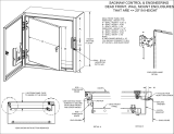
Type S braking resistor enclosures can be mounted vertically or horizontally. If the unit is
mounted vertically, it is important that the resistor coils remain in a horizontal position. Also, if a
thermal switch is included with the unit, the switch should be positioned near the top of the
enclosure. See Figure 1 for vertical mounting details.
Figure 1: Resistor Mounting Orientation
CAUTION
Type A, D, G, and W enclosures must be installed with the mounting holes on a
horizontal surface.
Air Flow
Correct Vertical Mounting
(Front View)
Incorrect Vertical
Mounting

Dynamic Braking Resistors Instruction Manual
September 2020
9
Installation:
1. Remove the ventilated cover.
a. Type D, G, S, and W enclosures require a 5/16” wrench to remove the cover.
b. Type A and B enclosures require a 7/16” wrench to remove the cover.
2. Fasten the unit securely in place. Mounting holes can be found on the inside of the
enclosure. The enclosure styles are listed in the tables on the following pages, and the
dimensions for each enclosure style are listed starting on page 27.
a. Type S and W enclosures have 7/16” diameter mounting holes designed for 3/8”
hardware.
b. Type A, B, D, and G enclosures have 5/8” diameter mounting holes designed for
½” hardware.
3. Remove the proper knockout after determining a suitable entry point. It is preferable to
route conduit near the bottom of the resistor enclosure.
a. Type D, G, S, and W enclosures have conduit knockouts for easy connection.
b. Type A and B enclosures require field punching for conduit entry.
4. After attaching conduit, pull wiring into the enclosure for connection to resistor. Refer to
the Wiring section in this manual or the CDBR braking unit or Regenerative Power
Module manuals for correct wire sizes. Be sure to properly ground the resistor
enclosure to prevent electrical shock.
a. If connecting directly to the terminals on the resistor elements, it is recommended
to use high temperature silicon or Teflon wire rated for at least 200ºC.
b. Try to route wiring along the bottom of the enclosure and avoid running the wiring
near the resistor elements.
c. If your braking resistor contains a factory wired terminal block, then you may
connect to the unit with standard 90ºC rated wire.
5. If an optional thermal switch is included with the unit, then connect control wiring directly
to the #8 terminals.
a. Type A and B enclosures with the thermal switch option are pre-wired to a
terminal block with #10 terminals, located in the bottom of the resistor enclosure.
b. Thermal sensing switches are available with either normally closed or normally
open contacts.
6. After installing and wiring to your Dynamic Braking Resistor, return the ventilated cover
to its proper position. Securely tighten cover hardware (do not exceed 20 inch-pounds
of torque).
Maintenance: Periodically check the unit for loose connections and accumulation of dust or
dirt on the inside and outside of the resistor enclosure.
1) Remove all power before servicing the unit to avoid electrical shock.
2) Allow at least ten minutes, after input power has been removed, for the VFD bus
voltage to discharge. Electric shock can cause serious injury or death.
3) Allow the resistor unit to cool before servicing (contact may result in burn injury).
Resistor elements should not glow red under normal operating conditions. If the resistor
elements glow red, you may need a higher rated braking resistor.

Dynamic Braking Resistors Instruction Manual
September 2020
10
CMAA Ratings
Magnetek Dynamic Braking Resistor duty cycles are based on Magnetek’s interpretation of
CMAA 70-2 Crane Classification specification. Consult Magnetek for application assistance
where actual duty cycles exceed the below definitions for any class of service, or for
applications involving special environmental conditions such as high ambient temperatures.
If lowering duration is greater than 60 seconds, contact Magnetek for application assistance.
CMAA Class C
Resistors for CMAA Class C service are based upon ten cycles per hour with an
average 50% load. A typical cycle is defined as follows:
Motion
Duration
Load
Raise
30 sec
50 %
Traverse
60 sec
50 %
Lower
30 sec
50 %
Raise
30 sec
10 %
Traverse
30 sec
10 %
Deceleration time for traverse motions is assumed to be 5 seconds, with a maximum
120% retarding torque.
CMAA Class D
Resistors for CMAA Class D service are based upon twenty cycles per hour with an
average 65% load. A typical cycle is defined as follows:
Motion
Duration
Load
Raise
30 sec
65 %
Traverse
60 sec
65 %
Lower
30 sec
65 %
Raise
30 sec
10 %
Traverse
30 sec
10 %
Deceleration time for traverse motions is assumed to be 3 seconds, with a maximum
150% retarding torque.
CMAA Class E
Resistors for CMAA Class E service are based upon twenty-five cycles per hour with
an average 100% load. A typical cycle is defined as follows:
Motion
Duration
Load
Raise
24 sec
100 %
Traverse
24 sec
100 %
Lower
24 sec
100 %
Raise
24 sec
10 %
Traverse
24 sec
10 %
Deceleration time for traverse motions is assumed to be 3 seconds, with a maximum
160% retarding torque.

Dynamic Braking Resistors Instruction Manual
September 2020
11
CMAA Class F
Resistors for CMAA Class F service are based upon continuous service loads
approaching rated capacity. A typical cycle is defined as follows:
Motion
Load
Raise
100 %
Traverse
100 %
Lower
100 %
Raise
50 %
Traverse
50 %
Deceleration time for traverse motions is assumed to be 2 seconds, with a maximum
175% retarding torque.
Technical Support: If you have any questions about your braking resistor, contact
Magnetek for assistance at 800.288.8178. Outside the U.S. and Canada call
1.262.783.3500, press 3.

Dynamic Braking Resistors Instruction Manual
September 2020
12
Specifications
230 Volt Traverse Motions – Indoor
CMAA Class A, B, C CMAA Class D CMAA Class E CMAA Class F
Part #
EDB_
Encl.
Style
Weight
(lbs.)
Part #
EDB_
Encl.
Style
Weight
(lbs.)
Part #
EDB_
Encl.
Style
Weight
(lbs.)
Part #
EDB_
Encl.
Style
Weight
(lbs.)
- - - 2001 DTP P1 1 - - - - - -
- - - 2004 DTP S1 7 - - - - - -
- - - 2005 DTP S1 7 - - - - - -
- - - 2006 DTP S1 7 - - - - - -
- - - 2011 DTP S1 7 - - - - - -
- - - 2015 DTP S2 9 - - - - - -
- - - 2017 DTP S2 9 - - - - - -
2001 CT SPC 1 2001 DT S1 6 2001 ET S1 7 2001 FT S1 7
2003 CT P1 1 2003 DT S1 7 2003 ET S1 7 2003 FT S1 7
2006 CT P2 1 2006 DT S1 7 2006 ET S1 7 2006 FT S2 9
2009 CT P2 1 2009 DT S1 7 2009 ET S2 9 2009 FT S2 9
2015 CT P3 1 2015 DT S2 9 2015 ET S2 9 2015 FT S3 13
2022 CT S1 7 2022 DT S2 9 2022 ET S3 13 2022 FT S4 16
2028 CT S2 9 2028 DT S3 13 2028 ET S4 16 2028 FT S5 18
2042 CT S2 9 2042 DT S4 16 2042 ET S6 16 2042 FT S6 19
2054 CT S3 13 2054 DT S6 17 2054 ET S6 18 2054 FT S8 25
2068 CT S6 15 2068 DT S6 19 2068 ET S6 21 2068 FT S8 24
2080 CT S6 15 2080 DT S6 20 2080 ET S8 23 2080 FT S12 29
2104 CT S6 16 2104 DT S9 21 2104 ET S12 27 2104 FT S18 43
2130 CT S6 18 2130 DT S9 29 2130 ET S12 30 2130 FT S18 39
2154 CT S8 20 2154 DT S12 29 2154 ET S12 35 2154 FT S30 61
2192 CT S6 21 2192 DT (2) S8 44 2192 ET (2) S8 56 2192 FT (2) S18 84
2248 CT (2) S6 36 2248 DT (2) S8 54 2248 ET (2) S12 62 2248 FT (2) S18 80
2312 CT (2) S6 40 2312 DT (2) S12 58 2312 ET (2) S18 76 2312 FT (2) A2 140

Dynamic Braking Resistors Instruction Manual
September 2020
13
230 Volt Hoist Motions – Indoor
CMAA Class A, B, C CMAA Class D CMAA Class E CMAA Class F
Part #
EDB_
Encl.
Style
Weight
(lbs.)
Part #
EDB_
Encl.
Style
Weight
(lbs.)
Part #
EDB_
Encl.
Style
Weight
(lbs.)
Part #
EDB_
Encl.
Style
Weight
(lbs.)
2001 CH S1 6 2001 DH S1 6 2001 EH S1 7 2001 FH S1 7
2003 CH S1 7 2003 DH S1 7 2003 EH S2 9 2003 FH S2 9
2006 CH S2 9 2006 DH S2 9 2006 EH S2 9 2006 FH S4 16
2009 CH S2 9 2009 DH S3 13 2009 EH S3 13 2009 FH S5 18
2015 CH S3 13 2015 DH S4 16 2015 EH S5 18 2015 FH S6 18
2022 CH S4 16 2022 DH S6 18 2022 EH S6 19 2022 FH S12 28
2028 CH S5 18 2028 DH S8 22 2028 EH S6 18 2028 FH S12 31
2042 CH S6 18 2042 DH S12 28 2042 EH S12 30 2042 FH S12 29
2054 CH S8 22 2054 DH S12 27 2054 EH S12 27 2054 FH S18 40
2068 CH S8 27 2068 DH S18 39 2068 EH S18 38 2068 FH S24 56
2080 CH S12 26 2080 DH S18 45 2080 EH S18 44 2080 FH S30 57
2104 CH S18 39 2104 DH S30 54 2104 EH S30 54 2104 FH A3 114
2130 CH S18 45 2130 DH S30 61 2130 EH A2 81 2130 FH A3 131
2154 CH S18 46 2154 DH A2 85 2154 EH A3 118 2154 FH A3 154
2192 CH A2 77 2192 DH (2) S18 94 2192 EH (2) S30 110 2192 FH (2) A2 178
2248 CH (2) S24 96 2248 DH (2) A2 154 2248 EH (2) A2 166 2248 FH (2) A3 250
2312 CH (2) S30 108 2312 DH (2) A2 170 2312 EH (2) A3 236 2312 FH (2) A3 294

Dynamic Braking Resistors Instruction Manual
September 2020
14
460 Volt Traverse Motions – Indoor
CMAA Class A, B, C CMAA Class D CMAA Class E CMAA Class F
Part #
EDB_
Encl.
Style
Weight
(lbs.)
Part #
EDB_
Encl.
Style
Weight
(lbs.)
Part #
EDB_
Encl.
Style
Weight
(lbs.)
Part #
EDB_
Encl.
Style
Weight
(lbs.)
- - - 4001 DTP SPC 1 - - - - - -
- - - 4002 DTP S1 6 - - - - - -
- - - 4004 DTP S1 7 - - - - - -
- - - 4005 DTP S1 7 - - - - - -
- - - 4008 DTP S2 9 - - - - - -
4001 CT P1 1 4001 DT S1 6 4001 ET S1 7 4001 FT S1 7
4003 CT P2 1 4003 DT S1 7 4003 ET S1 7 4003 FT S2 9
4004 CT P2 1 4004 DT S1 7 4004 ET S2 9 4004 FT S2 9
4007 CT P3 1 4007 DT S2 9 4007 ET S2 9 4007 FT S3 13
4011 CT S1 7 4011 DT S2 9 4011 ET S3 13 4011 FT S4 16
4014 CT S2 9 4014 DT S3 13 4014 ET S4 16 4014 FT S5 18
4021 CT S2 9 4021 DT S4 16 4021 ET S6 20 4021 FT S8 25
4027 CT S3 13 4027 DT S5 18 4027 ET S8 24 4027 FT S8 23
4034 CT S3 13 4034 DT S6 20 4034 ET S8 24 4034 FT S9 23
4040 CT S4 16 4040 DT S6 18 4040 ET S9 22 4040 FT S12 29
4052 CT S5 18 4052 DT S6 19 4052 ET S12 27 4052 FT S18 42
4065 CT S6 17 4065 DT S9 23 4065 ET S15 36 4065 FT S18 38
4077 CT S6 18 4077 DT S10 30 4077 ET S18 40 4077 FT S30 55
4096 CT S8 23 4096 DT S12 28 4096 ET S18 47 4096 FT S30 62
4124 CT S8 25 4124 DT S24 49 4124 ET S24 53 4124 FT A2 78
4155 CT S12 28 4155 DT S24 50 4155 ET A2 73 4155 FT A3 118
4175 CT S12 34 4175 DT S24 54 4175 ET A2 85 4175 FT (2) S24 96
4240 CT (2) S8 50 4240 DT (2) S15 80 4240 ET (2) S30 122 4240 FT (2) A2 158
4300 CT (2) S12 52 4300 DT (2) S24 102 4300 ET (2) A2 148 4300 FT (2) A3 208
4340 CT (2) S12 58 4340 DT (2) S24 110 4340 ET (2) A2 174 4340 FT (3) S30 198
4460 CT (2) S18 80 4460 DT (3) S24 150 4460 ET (3) A2 219 4460 FT (3) A3 354
4515 CT (3) S12 87 4515 DT (3) S24 162 4515 ET (3) A2 261 4515 FT (4) A2 308
4590 CT (3) S18 120 4590 DT (4) S24 204 4590 ET (4) A2 296 4590 FT (4) A3 416
4605 CT (3) S18 120 4605 DT (4) S24 204 4605 ET (4) A2 292 4605 FT (4) A3 416
4810 CT (4) S18 160 4810 DT (5) S24 270 4810 ET (5) A2 405 4810 FT (5) A3 590
4865 CT (4) S18 156 4865 DT (5) S24 270 4865 ET (5) A2 425 4865 FT (6) A3 624
41090 CT (5) S18 195 41090 DT (6) S30 330 41090 ET (7) A2 567 41090 FT (7) A3 826

Dynamic Braking Resistors Instruction Manual
September 2020
15
460 Volt Hoist Motions – Indoor
CMAA Class A, B, C CMAA Class D CMAA Class E CMAA Class F
Part #
EDB_
Encl.
Style
Weight
(lbs.)
Part #
EDB_
Encl.
Style
Weight
(lbs.)
Part #
EDB_
Encl.
Style
Weight
(lbs.)
Part #
EDB_
Encl.
Style
Weight
(lbs.)
4001 CH S1 7 4001 DH S1 7 4001 EH S2 9 4001 FH S3 13
4003 CH S2 9 4003 DH S2 9 4003 EH S3 13 4003 FH S4 16
4004 CH S2 9 4004 DH S3 13 4004 EH S4 16 4004 FH S5 18
4007 CH S3 13 4007 DH S5 18 4007 EH S5 18 4007 FH S8 24
4011 CH S4 16 4011 DH S6 20 4011 EH S8 24 4011 FH S12 33
4014 CH S5 18 4014 DH S8 25 4014 EH S10 30 4014 FH S15 30
4021 CH S8 24 4021 DH S12 33 4021 EH S15 31 4021 FH S15 31
4027 CH S10 30 4027 DH S15 30 4027 EH S15 31 4027 FH S24 47
4034 CH S12 33 4034 DH S15 31 4034 EH S24 51 4034 FH S24 56
4040 CH S12 26 4040 DH S24 49 4040 EH S24 48 4040 FH S30 55
4052 CH S15 33 4052 DH S24 46 4052 EH S24 47 4052 FH A2 80
4065 CH S24 50 4065 DH S30 68 4065 EH A2 75 4065 FH A3 122
4077 CH S24 49 4077 DH S30 58 4077 EH A2 86 4077 FH A3 117
4096 CH S30 58 4096 DH A2 92 4096 EH A3 109 4096 FH A4 173
4124 CH A2 78 4124 DH A3 123 4124 EH A4 156 4124 FH A5 227
4155 CH A3 100 4155 DH A4 162 4155 EH A5 211 4155 FH A6 293
4175 CH A3 115 4175 DH A5 204 4175 EH A5 212 4175 FH (2) A4 308
4240 CH (2) A2 158 4240 DH (2) A3 206 4240 EH (2) A4 288 4240 FH (2) A6 494
4300 CH (2) A3 206 4300 DH (2) A4 328 4300 EH (2) A5 430 4300 FH (2) A6 600
4340 CH (2) A3 234 4340 DH (2) A5 416 4340 EH (2) A5 432 4340 FH (3) A5 582
4460 CH (2) A4 310 4460 DH (3) A4 486 4460 EH (3) A5 633 4460 FH (3) A6 879
4515 CH (3) A3 351 4515 DH (3) A5 612 4515 EH (3) A5 648 4515 FH (4) A6 1036
4590 CH (3) A3 381 4590 DH (4) A4 656 4590 EH (4) A5 860 4590 FH (4) A6 1224
4605 CH (3) A4 471 4605 DH (4) A4 656 4605 EH (4) A5 844 4605 FH (4) A6 1224
4810 CH (4) A4 628 4810 DH (5) A5 1075 4810 EH (5) A5 1080 4810 FH (5) A7 1465
4865 CH (4) A4 620 4865 DH (5) A5 1020 4865 EH (5) A5 1060 4865 FH (6) A6 1836
41090 CH (5) A4 775 41090 DH (6) A5 1296 41090 EH (7) A5 1477 41090 FH (7) A6 2051

Dynamic Braking Resistors Instruction Manual
September 2020
16
575 Volt Traverse Motions – Indoor
CMAA Class A, B, C CMAA Class D CMAA Class E CMAA Class F
Part #
EDB_
Encl.
Style
Weight
(lbs.)
Part #
EDB_
Encl.
Style
Weight
(lbs.)
Part #
EDB_
Encl.
Style
Weight
(lbs.)
Part #
EDB_
Encl.
Style
Weight
(lbs.)
5003 CT S1 6 5003 DT S1 7 5003 ET S2 9 5003 FT S2 9
5004 CT S1 7 5004 DT S2 9 5004 ET S2 9 5004 FT S2 9
5006 CT S1 7 5006 DT S2 9 5006 ET S2 9 5006 FT S3 13
5009 CT S1 7 5009 DT S3 13 5009 ET S3 13 5009 FT S4 16
5011 CT S2 9 5011 DT S3 13 5011 ET S4 16 5011 FT S5 18
5017 CT S2 9 5017 DT S4 16 5017 ET S5 18 5017 FT S8 25
5022 CT S3 13 5022 DT S5 18 5022 ET S8 24 5022 FT S10 30
5027 CT S3 13 5027 DT S6 20 5027 ET (2) S5 36 5027 FT (2) S6 40
5032 CT S4 16 5032 DT (2) S4 32 5032 ET (2) S5 36 5032 FT (2) S8 48
5041 CT (2) S3 26 5041 DT (2) S5 36 5041 ET (2) S8 48 5041 FT (2) S10 60
5052 CT (2) S3 26 5052 DT (2) S6 40 5052 ET (3) S6 60 5052 FT (3) S8 75
5062 CT (2) S4 32 5062 DT (3) S5 54 5062 ET (3) S8 72 5062 FT (3) S10 90
5077 CT (3) S3 39 5077 DT (3) S6 60 5077 ET (3) S8 75 5077 FT (4) S9 108
5099 CT (3) S4 48 5099 DT (4) S6 80 5099 ET (4) S8 100 5099 FT (5) S10 150
5125 CT (4) S4 64 5125 DT (5) S6 100 5125 ET (5) S8 125 5125 FT (6) S10 180
5144 CT (5) S3 65 5144 DT (6) S6 120 5144 ET (6) S8 150 5144 FT (7) S10 210
5192 CT (6) S4 96 5192 DT (7) S6 140 5192 ET (8) S8 200 5192 FT (9) S10 270
- - - - - - 5052M ET S15 33 5052M FT S18 48
- - - 5062M DT S12 28 5062M ET S18 44 5062M FT S30 67
5077M CT S9 24 5077M DT S18 45 5077M ET S24 59 5077M FT S30 80
5099M CT S9 23 5099M DT S18 50 5099M ET S30 76 5099M FT S30 89
5125M CT S12 32 5125M DT S24 67 5125M ET A3 89 5125M FT A4 150
5144M CT S15 37 5144M DT S24 74 5144M ET S30 93 5144M FT A3 133
5192M CT S18 41 5192M DT A3 116 5192M ET A4 168 5192M FT (2) S30 178

Dynamic Braking Resistors Instruction Manual
September 2020
17
575 Volt Hoist Motions – Indoor
CMAA Class A, B, C CMAA Class D CMAA Class E CMAA Class F
Part #
EDB_
Encl.
Style
Weight
(lbs.)
Part #
EDB_
Encl.
Style
Weight
(lbs.)
Part #
EDB_
Encl.
Style
Weight
(lbs.)
Part #
EDB_
Encl.
Style
Weight
(lbs.)
5003 CH S2 9 5003 DH S3 13 5003 EH S3 13 5003 FH S4 16
5004 CH S2 9 5004 DH S3 13 5004 EH S4 16 5004 FH S5 18
5006 CH S3 13 5006 DH S5 18 5006 EH S5 18 5006 FH S8 25
5009 CH S4 16 5009 DH S6 20 5009 EH S8 24 5009 FH S12 33
5011 CH S5 18 5011 DH S8 25 5011 EH S8 25 5011 FH S15 38
5017 CH S8 25 5017 DH S12 33 5017 EH S15 31 5017 FH S24 43
5022 CH S10 30 5022 DH S15 31 5022 EH S18 37 5022 FH S30 57
5027 CH S12 33 5027 DH S15 31 5027 EH (2) S12 66 5027 FH (2) S18 74
5032 CH S12 26 5032 DH (2) S12 66 5032 EH (2) S15 76 5032 FH (2) S24 88
5041 CH (2) S10 60 5041 DH (2) S15 60 5041 EH (2) S15 62 5041 FH (2) S18 76
5052 CH (2) S12 66 5052 DH (2) S15 62 5052 EH (3) S15 93 5052 FH (3) S24 129
5062 CH (2) S12 52 5062 DH (3) S15 90 5062 EH (3) S15 93 5062 FH (3) S18 114
5077 CH (3) S10 90 5077 DH (3) S15 96 5077 EH (3) S18 108 5077 FH (4) S24 172
5099 CH (3) S15 93 5099 DH (4) S15 128 5099 EH (4) S18 148 5099 FH (5) S24 215
5125 CH (4) S12 104 5125 DH (5) S15 160 5125 EH (5) S18 185 5125 FH (6) S18 228
5144 CH (5) S12 135 5144 DH (6) S18 216 5144 EH (6) S15 192 5144 FH (7) S18 266
5192 CH (6) S12 156 5192 DH (7) S15 217 5192 EH (8) S15 256 5192 FH (9) S24 423
- - - - - - 5052M EH A2 88 5052M FH A3 106
- - - 5062M DH A2 91 5062M EH A3 130 5062M FH A4 99
5077M CH S24 55 5077M DH A4 132 5077M EH A3 142 5077M FH A6 230
5099M CH A2 99 5099M DH A3 158 5099M EH A5 196 5099M FH A6 267
5125M CH A3 137 5125M DH A4 174 5125M EH A5 229 5125M FH A7 350
5144M CH A3 121 5144M DH A5 221 5144M EH A6 285 5144M FH A8 407
5192M CH A5 214 5192M DH A6 258 5192M EH A7 331 5192M FH (2) A6 548

Dynamic Braking Resistors Instruction Manual
September 2020
18
230 Volt Traverse Motions - Weatherproof Louvered
CMAA Class C CMAA Class D CMAA Class E CMAA Class F
Part #
EDB_WL
Encl.
Style
Weight
(lbs.)
Part #
EDB_WL
Encl.
Style
Weight
(lbs.)
Part #
EDB_WL
Encl.
Style
Weight
(lbs.)
Part #
EDB_WL
Encl.
Style
Weight
(lbs.)
- - - 2004 DTP W1 7 - - - - - -
- - - 2005 DTP W1 7 - - - - - -
- - - 2006 DTP W1 7 - - - - - -
- - - 2011 DTP W1 7 - - - - - -
- - - 2015 DTP W2 9 - - - - - -
- - - 2017 DTP W2 9 - - - - - -
2001 CT W1 6 2001 DT W1 6 2001 ET W1 7 2001 FT W1 7
2003 CT W1 7 2003 DT W1 7 2003 ET W1 7 2003 FT W1 7
2006 CT W1 7 2006 DT W1 7 2006 ET W1 7 2006 FT W2 9
2009 CT W1 7 2009 DT W1 7 2009 ET W2 9 2009 FT W2 9
2015 CT W1 7 2015 DT W2 9 2015 ET W2 9 2015 FT W3 13
2022 CT W1 7 2022 DT W2 9 2022 ET W3 13 2022 FT W4 16
2028 CT W2 9 2028 DT W3 13 2028 ET W4 16 2028 FT W5 18
2042 CT W2 9 2042 DT W4 16 2042 ET W6 16 2042 FT W6 19
2054 CT W3 13 2054 DT W6 17 2054 ET W6 18 2054 FT W8 25
2068 CT W6 15 2068 DT W6 19 2068 ET W6 21 2068 FT W8 24
2080 CT W6 15 2080 DT W6 20 2080 ET W8 23 2080 FT W12 33
2104 CT W6 16 2104 DT W9 25 2104 ET W12 31 2104 FT W18 47
2130 CT W6 18 2130 DT W9 33 2130 ET W12 34 2130 FT W18 43
2154 CT W8 20 2154 DT W12 33 2154 ET W12 39 2154 FT W30 65
2192 CT W6 21 2192 DT (2) W8 44 2192 ET (2) W8 56 2192 FT (2) W18 92
2248 CT (2) W6 36 2248 DT (2) W8 54 2248 ET (2) W12 70 2248 FT (2) W18 88
2312 CT (2) W6 40 2312 DT (2) W12 66 2312 ET (2) W18 84 2312 FT (2) B2 202

Dynamic Braking Resistors Instruction Manual
September 2020
19
230 Volt Hoist Motions – Weatherproof Louvered
CMAA Class A, B, C CMAA Class D CMAA Class E CMAA Class F
Part #
EDB_WL
Encl.
Style
Weight
(lbs.)
Part #
EDB_WL
Encl.
Style
Weight
(lbs.)
Part #
EDB_WL
Encl.
Style
Weight
(lbs.)
Part #
EDB_WL
Encl.
Style
Weight
(lbs.)
2001 CH W1 6 2001 DH W1 6 2001 EH W1 7 2001 FH W1 7
2003 CH W1 7 2003 DH W1 7 2003 EH W2 9 2003 FH W2 9
2006 CH W2 9 2006 DH W2 9 2006 EH W2 9 2006 FH W4 16
2009 CH W2 9 2009 DH W3 13 2009 EH W3 13 2009 FH W5 18
2015 CH W3 13 2015 DH W4 16 2015 EH W5 18 2015 FH W6 18
2022 CH W4 16 2022 DH W6 18 2022 EH W6 19 2022 FH W12 32
2028 CH W5 18 2028 DH W8 22 2028 EH W6 18 2028 FH W12 35
2042 CH W6 18 2042 DH W12 32 2042 EH W12 34 2042 FH W12 33
2054 CH W8 22 2054 DH W12 31 2054 EH W12 31 2054 FH W18 44
2068 CH W8 27 2068 DH W18 43 2068 EH W18 42 2068 FH W24 60
2080 CH W12 30 2080 DH W18 49 2080 EH W18 48 2080 FH W30 61
2104 CH W18 43 2104 DH W30 58 2104 EH W30 58 2104 FH B3 129
2130 CH W18 49 2130 DH W30 65 2130 EH B3 112 2130 FH B4 167
2154 CH W18 50 2154 DH B3 116 2154 EH B3 133 2154 FH B4 190
2192 CH B3 108 2192 DH (2) W18 102 2192 EH (2) W30 118 2192 FH (2) B3 240
2248 CH (2) W24 104 2248 DH (2) B3 216 2248 EH (2) B3 228 2248 FH (2) B4 322
2312 CH (2) W30 116 2312 DH (2) B3 232 2312 EH (2) B3 266 2312 FH (2) B4 366

Dynamic Braking Resistors Instruction Manual
September 2020
20
460 Volt Traverse Motions - Weatherproof Louvered
CMAA Class A, B, C CMAA Class D CMAA Class E CMAA Class F
Part #
EDB_WL
Encl.
Style
Weight
(lbs.)
Part #
EDB_WL
Encl.
Style
Weight
(lbs.)
Part #
EDB_WL
Encl.
Style
Weight
(lbs.)
Part #
EDB_WL
Encl.
Style
Weight
(lbs.)
- - - 4001 DTP W1 6 - - - - - -
- - - 4002 DTP W1 6 - - - - - -
- - - 4004 DTP W1 7 - - - - - -
- - - 4005 DTP W1 7 - - - - - -
- - - 4008 DTP W2 9 - - - - - -
4001 CT W1 6 4001 DT W1 6 4001 ET W1 7 4001 FT W1 7
4003 CT W1 7 4003 DT W1 7 4003 ET W1 7 4003 FT W2 9
4004 CT W1 7 4004 DT W1 7 4004 ET W2 9 4004 FT W2 9
4007 CT W1 7 4007 DT W2 9 4007 ET W2 9 4007 FT W3 13
4011 CT W1 7 4011 DT W2 9 4011 ET W3 13 4011 FT W4 16
4014 CT W2 9 4014 DT W3 13 4014 ET W4 16 4014 FT W5 18
4021 CT W2 9 4021 DT W4 16 4021 ET W6 20 4021 FT W8 25
4027 CT W3 13 4027 DT W5 18 4027 ET W8 24 4027 FT W8 23
4034 CT W3 13 4034 DT W6 20 4034 ET W8 24 4034 FT W9 27
4040 CT W4 16 4040 DT W6 18 4040 ET W9 26 4040 FT W12 33
4052 CT W5 18 4052 DT W6 19 4052 ET W12 31 4052 FT W18 46
4065 CT W6 17 4065 DT W9 27 4065 ET W15 40 4065 FT W18 42
4077 CT W6 18 4077 DT W10 30 4077 ET W18 44 4077 FT W30 59
4096 CT W8 23 4096 DT W12 32 4096 ET W18 51 4096 FT W30 66
4124 CT W8 25 4124 DT W24 53 4124 ET W24 57 4124 FT B3 109
4155 CT W12 32 4155 DT W24 54 4155 ET B3 104 4155 FT B4 154
4175 CT W12 38 4175 DT W24 58 4175 ET B3 116 4175 FT (2) W24 104
4240 CT (2) W8 50 4240 DT (2) W15 88 4240 ET (2) W30 130 4240 FT (2) B3 220
4300 CT (2) W12 60 4300 DT (2) W24 110 4300 ET (2) B3 210 4300 FT (2) B3 238
4340 CT (2) W12 66 4340 DT (2) W24 118 4340 ET (2) B3 236 4340 FT (3) W30 210
4460 CT (2) W18 88 4460 DT (3) W24 162 4460 ET (3) B3 312 4460 FT (3) B4 462
4515 CT (3) W12 99 4515 DT (3) W24 174 4515 ET (3) B3 354 4515 FT (4) B3 432
4590 CT (3) W18 132 4590 DT (4) W24 220 4590 ET (4) B3 420 4590 FT (4) B3 476
4605 CT (3) W18 132 4605 DT (4) W24 220 4605 ET (4) B3 416 4605 FT (4) B3 476
4810 CT (4) W18 175 4810 DT (5) W24 289 4810 ET (5) B3 559 4810 FT (5) B4 772
4865 CT (4) W18 174 4865 DT (5) W24 289 4865 ET (5) B3 580 4865 FT (6) B3 715
41090 CT (5) W18 217 41090 DT (6) W30 355 41090 ET (7) B3 783 41090 FT (7) B4 1081
/