Page is loading ...

1031E-1105
LT-200CL
3CMOS High Speed Color
Line Scan Camera
Document Version: Ver.1.0
LT-200CL_Ver.1.0_May2011
User's Manual

LT-200CL
2
Notice
The material contained in this manual consists of information that is proprietary to JAI Ltd.,
Japan and may only be used by the purchasers of the product. JAI Ltd., Japan makes no
warranty for the use of its product and assumes no responsibility for any errors which may
appear or for damages resulting from the use of the information contained herein. JAI Ltd.,
Japan reserves the right to make changes without notice.
Company and product names mentioned in this manual are trademarks or registered
trademarks of their respective owners.
Warranty
For information about the warranty, please contact your factory representative.
Certifications
CE compliance
As defined by the Directive 2004/108/EC of the European Parliament and of the Council, EMC
(Electromagnetic compatibility), JAI Ltd., Japan declares that LT-200CL complies with the
following provisions applying to its standards.
CISPR Pub.22 (Emission)
CISPR Pub.24 (Immunity)
IEC61000-4-2 Conforming Level 4 (Electrostatic discharge immunity test)
FCC
This equipment has been tested and found to comply with the limits for a Class B digital device,
pursuant to Part 15 of the FCC Rules. These limits are designed to provide reasonable
protection against harmful interference in a residential installation. This equipment
generates, uses and can radiate radio frequency energy and, if not installed and used in
accordance with the instructions, may cause harmful interference to radio communications.
However, there is no guarantee that interference will not occur in a particular installation. If
this equipment does cause harmful interference to radio or television reception, which can be
determined by turning the equipment off and on, the user is encouraged to try to correct the
interference by one or more of the following measures:
- Reorient or relocate the receiving antenna.
- Increase the separation between the equipment and receiver.
- Connect the equipment into an outlet on a circuit different from that to which the receiver
is connected.
- Consult the dealer or an experienced radio/TV technician for help.
Warning
Changes or modifications to this unit not expressly approved by the party
responsible for FCC compliance could void the user’s authority to operate the
equipment.

LT-200CL
Supplement
The following statement is related to the regulation on “ Measures for the Administration
of the control of Pollution by Electronic Information Products “ , known as “ China RoHS “.
The table shows contained Hazardous Substances in this camera.
mark shows that the environment-frien dly u se period of containe d Hazard ous
Substances is 15 years.
嶷勣廣吭並㍻
嗤蕎嗤墾麗嵎賜圷殆兆各式根楚燕
功象嶄鯖繁酎慌才忽佚連恢匍何〆窮徨佚連恢瞳麟半陣崙砿尖一隈〇
云恢瞳ゞ 嗤蕎
嗤
墾麗嵎賜圷殆兆各式根楚燕 〃泌和
桟隠聞喘豚㍉
窮徨佚連恢瞳嶄根嗤議嗤蕎嗤墾麗嵎賜圷殆壓屎械聞喘議訳周和音氏窟伏翌
亶賜融延、窮徨佚連恢瞳喘薩聞喘乎窮徨佚連恢瞳音氏斤桟廠夛撹冢嶷麟半
賜斤児繁附、夏恢夛撹冢嶷鱒墾議豚㍉。
方忖仝15々葎豚㍉15定。

LT-200CL
3
- Contents –
1. General ........................................................................................................ 5
2. Camera nomenclature ...................................................................................... 5
3. Main features ................................................................................................. 5
4. Locations and functions .................................................................................... 6
4.1. Main unit ................................................................................................ 6
4.2. Rear Panel and indicators ............................................................................ 7
Note: Factory default settings for both functions are “OFF”. ............................................. 7
5. Input and output (connectors, signals and circuits) ................................................... 8
5.1. 12-Pin Connector (Hirose) ............................................................................. 8
5.2. Digital Output / Interface Connectors for Camera Link ......................................... 8
5.3. Camera Link output ................................................................................... 9
5.4. Input and output circuits ............................................................................ 11
5.4.1 Trigger input ...................................................................................... 11
5.4.2 EEN/XEEN output (Exposure Enable ) ...................................................... 11
6. Functions and Operation.................................................................................. 12
6.1. Basic functions ........................................................................................ 12
6.2. Sensor layout and output timing ................................................................... 12
6.3. Key functions .......................................................................................... 13
6.3.1 Line rate (Command LR) ........................................................................ 13
6.3.2 Electronic shutter (Exposure) (Command PER, PEG, PEB) ................................. 13
6.3.3 EEN (Exposure Enable) function ............................................................... 14
6.3.4 Auto Reset mode ................................................................................. 14
6.3.5 Auto Interval Mode ............................................................................... 15
6.3.6 White balance .................................................................................... 16
6.3.7 Gain control ....................................................................................... 17
6.3.8 Setup(Black) level ................................................................................ 18
6.3.9 Knee correction .................................................................................. 18
6.3.10 PRNU (Pixel Response Non-Uniformity ) correction ....................................... 19
6.3.11 DSNU (Dark Signal Non-Uniformity) correction............................................. 20
6.3.12 Shading correction ............................................................................... 20
6.3.13 Binning ............................................................................................. 21
6.3.14 Sub-sampling (SRO=1) ........................................................................... 21
6.3.15 Windowing (SRO=2) .............................................................................. 22
6.3.16 Test pattern generator .......................................................................... 22
6.4. Operation modes ..................................................................................... 23
6.4.1 No-shutter mode with internal trigger ........................................................ 24
6.4.2 No-shutter mode with external trigger ....................................................... 25
6.4.3 Shutter-select mode with internal trigger ................................................... 28
6.4.4 Shutter-select mode with external trigger ................................................... 30
6.4.5 Pulse width control (PWC) mode .............................................................. 32
6.4.6 Compatibility of trigger modes and functions ............................................... 34
7. Configuring the camera ................................................................................... 35
7.1. RS-232C control ....................................................................................... 35
7.2. LT-200CL Command list ............................................................................. 36
8. Functions listed alphabetically by command acronyms ............................................. 41
8.1. Command AH – One-push AWB shutter ............................................................ 41
8.2. Command AHRS – Request status after One-Push AWB ......................................... 41
8.3. Command AL – Automatic Line Rate Reference Level .......................................... 41
8.4. Command AR – Automatic Line Rate setting ..................................................... 41
8.5 Command ARST – Auto reset mode ................................................................ 42
8.6 Command AW – Activate One-push Auto White Balance (AWB) - Gain ...................... 42
8.7 Command AWRS – Inquire the status after one-push AWB ..................................... 42
8.8 Command BA – Bit Allocation ....................................................................... 42

LT-200CL
4
8.9 Command BI – Binning (Horizontal only) ......................................................... 43
8.10 Command BL – Master Black Level ................................................................ 43
8.11 Commands BLR and BLB – Black level red and black level blue .............................. 43
8.12 Command BLM – Black level mode ................................................................ 43
8.13 Command EI – Interlocked R and B exposure with G ........................................... 43
8.14 Command GA – Gain level master / G channel.................................................. 44
8.15 Commands GAR and GAB – Red and blue gain levels ........................................... 44
8.16 Command GM – Gain mode ......................................................................... 44
8.17 Command KN – Knee ON/Off ....................................................................... 44
8.18 Commands KSR, KSG and KSB – Knee slope for R, G and B .................................... 44
8.19 Commands KPR, KPG and KPG – Knee point for R, G and B ................................... 44
8.20 Command LR - Line Rate (Scan Rate) ............................................................ 45
8.21 Command NR – Noise reduction ................................................................... 45
8.22 Command PBC – Select pixel black correction mode ........................................... 45
8.23 Command PBR – Run pixel black correction and store to user area ......................... 45
8.24 Command PBS – Inquire the status of after pixel black correction .......................... 46
8.25 Command PER – Programmable exposure – Red................................................. 46
8.26 Command PEG – Programmable exposure – Green ............................................. 46
8.27 Command PEB – Programmable exposure – Blue ................................................ 46
8.28 Command PGC – Pixel gain correction mode .................................................... 46
8.29 Command PGR – Run pixel gain correction and store in user area ........................... 47
8.30 Command PGS – Inquire the status after pixel gain correction............................... 47
8.31 Command SDC – Select shading correction mode ............................................... 47
8.32 Command SDR – Run shading correction ......................................................... 47
8.33 Command SDS – Request status after executing shading correction command ............ 49
8.34 Commands SGR,SGG,SGB – Gain Low, High ...................................................... 49
8.35 Command SRO – Sensor read out .................................................................. 49
8.36 Command TG – Trigger Origin ...................................................................... 49
8.37 Command TI – Trigger input ........................................................................ 49
8.38 Command TP – Trigger polarity .................................................................... 50
8.39 Command TR – Trigger Mode ....................................................................... 50
8.40 Command TS – Test pattern ........................................................................ 50
8.41 Command WB – White Balance .................................................................... 50
9. Camera Control Tool for LT-200CL ..................................................................... 51
9.1. Software Install ....................................................................................... 51
9.2. Open the Control Tool ............................................................................... 51
9.3. About Window ..................................................................................... 51
9.4. Communication Window .......................................................................... 52
9.5. Exposure/Trigger/Format Control window ....................................................... 54
9.6. Gain Control window ................................................................................ 54
9.7. Use Control tool ...................................................................................... 54
10. External appearance and Dimensions .................................................................. 56
11. Specifications ............................................................................................. 58
11.1 Typical data ............................................................................................ 58
11.2 Spectral sensitivity .................................................................................... 60
Appendix .......................................................................................................... 61
1. Precautions .............................................................................................. 61
2. Typical Sensor Characteristics ........................................................................ 61
3. Caution when mounting a lens on the camera ..................................................... 61
4. Caution when mounting the camera ................................................................. 61
5. Exportation .............................................................................................. 62
6. References ............................................................................................... 62
Change History ................................................................................................... 63
User's Record ..................................................................................................... 64

LT-200CL
5
1. General
LT-200CL is a 3CMOS line scan camera using three 2048 pixel line sensors mounted on a prism,
for the R, G and B channels. It operates with an 80 MHz pixel clock, resulting in a maximum line
rate of 30,383 lines per second.
The camera outputs digital data in 3 x 8 bits or 3 x 10 bits format via Camera Link. The camera
is configured by software through the serial communication port of the Camera Link interface,
or via RS-232C through a 12-pin Hirose connector.
The camera accepts M52 or F-mount lens.
The latest version of this operation manual can be downloaded from www.jai.com .
The latest camera control tool for the LT-200CL can be downloaded from www.jai.com .
For camera revision history, please contact your local JAI distributor
2. Camera nomenclature
The standard camera composition consists of:
LT-200CL camera body x 1
Lens mount/sensor protection cap x 1
The camera is available in the following versions:
LT-200CL-M52/-F
Where L stands for “Linear sensor” family, T stands for “Tri sensor”, 200 represents the
resolution “ 2048 pixels”, 200 represents variation with the same resolution and CL stands for
“CameraLink
®
” interface. M52 stands for M52 lens mount version and F stands for the Nikon F
mount version
3. Main features
3CMOS line scan camera with 2048 pixel resolution
Dichroic RGB beam splitter prism
30,383 lines per second scan rate
80 MHz pixel clock
3 x 8 bits or 3 x 10 bits output through Camera Link interface
Flat-field correction. Pixel-by-pixel compensation on each RGB channel
Flat shading compensation
Color shading compensation
One-push white balance
Knee correction
Noise reduction circuit ON/OFF
Pixel binning
Sub-sampling readout
Windowing readout
Test pattern generator(color bar, gray, white) for set-up and troubleshooting
Electronic shutter (for shutter selected modes)
Lens mount is M52 as a standard and F mount as a factory option
DC input range from +12 V to +24V
Short ASCII commands for set-up via RS 232C or Camera Link
Setup by Windows XP/Vista/7 software

LT-200CL
6
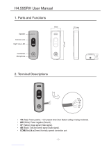
4. Locations and functions
4.1. Main unit
SW1
/ TRIG
DC IN
W.B.
TRIG
POWER/
DIGITAL I/ O - 2 DIGITAL I/ O - 1
Serial No.
FCC seal
①
②
③④
⑤
⑥
⑦
⑧
⑨
⑨
Fig. 1 Location of external features
1 Camera Link base connector (1) (*Note1)
2 Camera Link medium connector (2) (*Note1)
3 12-pin Hirose connector for DC +12, External trigger and RS-232C
4 LED indicator Orange, steady: Initializing or one-push operation
Green, steady: Operating, but not receiving external trigger
Green, flashing: Operating and receiving external trigger
5 One-push auto white balance button
6 SW-1 (refer to chapter 4.2)
7. M52 lens mount (Note 2)
8 Nikon F-Mount lens mount(Note2)
9 Mounting holes 8 x M3, depth 4.5mm (*Note3)
*Note1: When a Camera Link cable is connected to the camera, please do not excessively tighten
screws by using driver. The Camera Link receptacle on the camera might be damaged. For
security, the strength to tighten screws is less than 0.291 Newton Meter (Nm).Tightening by
hand is sufficient in order to achieve this.
*Note2: The rear protrusion of lens should be within 13mm for both M52 mount lens and
Nikon-F mount lens.
*Note3: The depth of mounting hole is 4.5mm . If the longer screws than 4.5mm are used, they may
damage the circuit board inside.

LT-200CL
7
4.2. Rear Panel and indicators
Fig.2 Rear panel
LED
There is a multi-color LED on the rear panel of the camera. It has the following functions:
Green (Steady)
Operating, but not receiving external trigger input
Green (Flashing)
Operating and receiving external trigger input.
Note that the flashing frequency does not correspond to the frequency of the trigger
signal.
Note: In no-shutter/internal and shutter select/internal modes, this LED does not
flash.
Orange
Initializing or executing one-push white balance
Push button
This push button is used for gain white balance.
DIP switch
SW-1 function
No
Function
Settings
ON
OFF
1
Serial communication
Hirose 12Pin
Camera link
2
Termination of External trigger
75Ω
TTL
Note: Factory default settings for both functions are “OFF”.
Fig.3 DIP switch
Rear panel indicator LED
OFF
ON
Serial
Communication
75 Ω
Push button
DIP switch

LT-200CL
8
5. Input and output (connectors, signals and circuits)
5.1. 12-Pin Connector (Hirose)
Type: HR10A-10R-12PB(71) Hirose (Male)
Use the part number HR10A-10P-12S for the cable side
Pin No.
Signal
Remarks
1
GND
2
DC in
+12V to +24V
3
GND
4
Reserved
Do not connect
5
GND
6
RxD in
RS-232C
7
TxD out
RS-232C
8
GND
9
XEEN out
10
Trigger in
TI=1, or set TI=0 for input via CL
11
―
12
GND
5.2. Digital Output / Interface Connectors for Camera Link
Type: 26P MRD Connector 3M 110226-1A10PL
Fig. 5 Camera Link connector
This camera can be used with all Camera Link products that comply with the AIA Camera Link
standard. Cables, transmission systems and frame grabbers/acquisition boards that do not
comply with the Camera Link standard may work with this camera, but JAI Camera Solutions
cannot be held responsible for loss in performance or damage of equipment, including the
camera.
Recommended cable assembly
3M 14B26-SZLB-XXX-OLC ( where XXX is the length of cable)
The applicable cable length is 0.5m to 10m.
14B26-SZ3B-XXX-03V(small diameter type) and 14B26-SZ3B-XXX-04C (high flexion type) can be
used but the length will be limited.
Connector 1 (24Bit, 30 Bit)
Pin No
In/Out
Name
Note
1,14
Shield
GND
2(-),15(+)
O
TxOUT0
Data out
3(-),16(+)
O
TxOUT1
4(-),17(+)
O
TxOUT2
5(-),18(+)
O
TxClk
Clock for CL
6(-),19(+)
O
TxOUT3
Data out
7(+),20(-)
I
SerTC (RxD)
LVDS Serial Control
8(-),21(+)
O
SerTFG (TxD)
9(-),22(+)
I
CC1 (Trigger)
Trigger
10(+),23(-)
I
CC2(Reserved)
11,24
N.C
12,25
N.C
13,26
Shield
GND
Fig.4 12-pin Hirose connector

LT-200CL
9
Connector 2 ( Used only for 3 x 10 Bit output)
Pin No
In/Out
Name
Note
1,14
Shield
GND
2(-),15(+)
O
TxOUT0
Data out
3(-),16(+)
O
TxOUT1
4(-),17(+)
O
TxOUT2
5(-),18(+)
O
TxClk
Clock for CL
6(-),19(+)
O
TxOUT3
Data out
7(+),20(-)
N.C
8(-),21(+)
N.C
9(-),22(+)
N.C
10(+),23(-)
N.C
11,24
N.C
12,25
N.C
13,26
Shield
GND
The LT-200CL follows the Camera Link standard in all respects.
Please refer to the Camera Link version 1.1 specifications for detailed information on bit
assignments of 24-bit RGB and 30-bit RGB output.
5.3. Camera Link output
RD9~RD0 : R Channel Camera Data(RD9=MSB, RD0=LSB)
GD9~GD0 : G Channel Camera Data(GD9=MSB, GD0=LSB)
BD9~BD0 : B Channel Camera Data(BD9=MSB, BD0=LSB)
× : Not in use
Port/Signal
24bit Output
30bit Output
Connector
Pin Name
Port A0
RD0
RD0
1
Tx0
Port A1
RD1
RD1
1
Tx1
Port A2
RD2
RD2
1
Tx2
Port A3
RD3
RD3
1
Tx3
Port A4
RD4
RD4
1
Tx4
Port A5
RD5
RD5
1
Tx6
Port A6
RD6
RD6
1
Tx27
Port A7
RD7
RD7
1
Tx5
Port B0
GD0
RD8
1
Tx7
Port B1
GD1
RD9
1
Tx8
Port B2
GD2
×
1
Tx9
Port B3
GD3
×
1
Tx12
Port B4
GD4
BD8
1
Tx13
Port B5
GD5
BD9
1
Tx14
Port B6
GD6
×
1
Tx10
Port B7
GD7
×
1
Tx11
Port C0
BD0
BD0
1
Tx15
Port C1
BD1
BD1
1
Tx18
Port C2
BD2
BD2
1
Tx19
Port C3
BD3
BD3
1
Tx20
Port C4
BD4
BD4
1
Tx21
Port C5
BD5
BD5
1
Tx22
Port C6
BD6
BD6
1
Tx16
Port C7
BD7
BD7
1
Tx17

LT-200CL
10
Port D0
×
×
2
Tx0
Port D1
×
×
2
Tx1
Port D2
×
×
2
Tx2
Port D3
×
×
2
Tx3
Port D4
×
×
2
Tx4
Port D5
×
×
2
Tx6
Port D6
×
×
2
Tx27
Port D7
×
×
2
Tx5
Port E0
×
GD0
2
Tx7
Port E1
×
GD1
2
Tx8
Port E2
×
GD2
2
Tx9
Port E3
×
GD3
2
Tx12
Port E4
×
GD4
2
Tx13
Port E5
×
GD5
2
Tx14
Port E6
×
GD6
2
Tx10
Port E7
×
GD7
2
Tx11
Port F0
×
GD8
2
Tx15
Port F1
×
GD9
2
Tx18
Port F2
×
×
2
Tx19
Port F3
×
×
2
Tx20
Port F4
×
×
2
Tx21
Port F5
×
×
2
Tx22
Port F6
×
×
2
Tx16
Port F7
×
×
2
Tx17
LVAL 1
1
Tx24
FVAL 1
1
Tx25
LVAL 2
2
Tx24
FVAL 2
2
Tx25
DVAL
1
Tx26
EEN
1
Tx23

LT-200CL
11
5.4. Input and output circuits
5.4.1 Trigger input
The External Trigger signal can be applied either through the Camera Link connector or at pin
10 of the 12-pin Hirose connector. The command to change this setting is TI (Trigger Input).
TI=0 for Camera Link connector (factory default) and TI=1 for 12-pin Hirose connector. The
input via the 12-pin Hirose connector is AC coupled.
To allow long pulses, which may be required when using the Pulse Width Control (PWC) trigger
mode, the input circuit is designed as a flip-flop circuit. The leading and trailing edges of the
trigger pulse activate the circuit.
The trigger input polarity can be changed by the command TP. At the 12-pin Hirose connector
the External Trigger input is 4V ± 2V (TTL). It can be changed to 75 ohm termination by a DIP
switch setting (SW 1) located on the rear panel.
5.4.2 EEN/XEEN output (Exposure Enable )
This output corresponds to the exposure (accumulation) time of the camera. It works with all
operation modes. It is, however, not active when the test pattern function is enabled.
The EEN signal is available at the Camera
Link connector and at the 12-pin Hirose
connector at the same time.
At the Camera Link connector this signal has
positive logic.
At pin 9 of the 12-pin Hirose connector the
signal has negative logic, and is therefore
named XEEN. The output circuit is a 75 ohm
complementary emitter follower. The
circuit is powered from the 5V supply,
resulting in an output level of more than 4V.
It is not terminated.
Fig. 7 XEEN Circuit (12-pin Hirose)
Fig. 6 Trigger input (12-pin Hirose)

LT-200CL
12
6. Functions and Operation
6.1. Basic functions
The LT-200CL is built around three high-performance CMOS line scan image sensors
mounted on a prism block, as illustrated in Figure 8.
Sensor interface
Process circuits
Auto black
DSNU correction
PRNU correction
Shading correction
Gain
Line matrix
User black setup
Digital binning
Camera link interface
Camera link
B a s e &
M e d i u m
Fig.8 Sensor block diagram
The incoming light is divided into three primary colors, Red, Blue and Green and
transmitted to each sensor. The output from each sensor is LVDS and it is converted to
parallel digital signals in the sensor interface. Each signal then is transmitted to
processing circuits which manipulate in the necessary characteristics and output via the
Camera Link interface. The functions in the processing circuits are described in the
following sections.
6.2. Sensor layout and output timing
The LT-200CL uses newly developed CMOS sensors which have 2048 effective pixels. Light
received on photodiodes is converted to electronic signals and these signals are handled
in a correlated double sampling circuit, analog gain circuit and analog digital converter
circuit. After that, digital signals are serialized and output. All those circuits are inside
the sensor package. CMOS sensors can provide higher rates and lower power consumption
than CCDs of equivalent resolution.
・・・・
TP : Transi ti on Pi xel s
AP : Act i ve Pi xel s
OB : Opti cal Bl ack Pi xel s
I s o : I s ol at i on St ages
・ ・ ・ ・
CDS, PGA, ADC
Di gi t al Process or
PDO<0>
PDO<1>
PDO<2>
Ser i al i zer
Tt r ansf er _dat a
OB0
OB2
OB3
OB4
OB5
OB6
OB7
2048
OB8
OB9
OB10
OB11
OB12
OB13
OB14
OB15
Opt i cal bl ack
Opt i cal bl ack
88
480
2544
Fig.9 Sensor layout

LT-200CL
13
TP : Tr ans i t i on Pi xel s
AP : Act i ve Pi xel s
OB : Opt i cal Bl ack Pi xel s
I s o : I s ol at i on St ages
LVAL : Li ne Val i d
DVAL : Dat a Val i d
LVAL
DVAL
Dat a
DM : Dummy or Tt r ans f er _dat a Pi xel s
DM
DM
DM
DM
D
M
DM
DM
DM
DM
DM
DM
DM
DM
DM
AP1
AP2
AP3
・ ・ ・ ・ ・ ・ ・ ・ ・ ・ ・ ・ ・ ・ ・ ・ ・
AP0
DM
DM
2048
AP+OB=2064
OB0
OB1
OB2
OB3
OB4
OB5
OB6
OB7
AP2047
AP2046
AP2045
AP2044
OB8
OB9
OB10
OB11
OB12
OB13
OB14
OB15
1CLK=12. 5ns
2544
DM
Effective Pixels Period
Fig.10 Video output timing
6.3. Key functions
6.3.1 Line rate (Command LR)
This function can set the line rate longer than 1L. Accordingly, it is possible to match the
camera scan rate with the object running speed, or to boost up the sensitivity by setting a
longer exposure time.
Adjusting range: 32.9125µs(1L) to 16.844ms
Adjusting unit: 12.5ns
Operation mode: TG=0 Internal trigger
Applicable mode: No-shutter/Internal, Shutter select/Internal
The line rate can be automatically configured (one-push auto line set) (Command:AR).
This function will calculate and set the line rate of the camera based on the Automatic
Line Rate Reference Level (Command :AL) and the scene illumination.
6.3.2 Electronic shutter (Exposure) (Command PER, PEG, PEB)
This function sets the exposure time regardless of line rate setting. The exposure time
can be set for red, blue, and green, respectively.
Command PER= 2064 to 1056720
PEG= 2064 to 1056720
PEB= 2064 to 1056720
Adjusting range: 25.8μs (2064clk) to 13.209ms (1056720clk)
(RGB individually)
Adjusting unit: 12.5 ns (1clock) (RGB individually)
Operation mode: Shutter select/internal trigger and shutter
select/external trigger
Note:
Exposure time can be set as mentioned before. However, if the line rate is shorter
than the exposure time, the accumulation time is determined by the line rate.
This should be noted especially in external trigger mode.

LT-200CL
14
Line rate > Exposure time
Exposur e B
Exposur e G
Exposur e R
( I nternal /Ext ernal )
Tr i gger
Line rate (LR) = 20000
Exposure (Rch) =22000
In this case, although the expsore time is set at 22000, but the actual exposure time is limited by the line rate, 20000.
Fig.11 Exposure setting should be less the line rate
6.3.3 EEN (Exposure Enable) function
This function outputs the timing for image accumulation in all operating modes except
test pattern output. The output can be through both the Hirose 12-pin and Camera Link
connectors. The polarity of this output is negative from the Hirose 12-pin connector and
positive from the Camera Link connector. These polarities cannot be changed.
Exposure B
Exposure G
Exposure R
EEN
(I nternal /External )
Tr i gger
EEN represents with the longets exposure time among R,G and B
Fig.12 EEN function
6.3.4 Auto Reset mode
In the No-Shutter and external trigger mode, when the trigger pulse is input after a long
interruption of more than 52ms, the image accumulated during the interruption of the
trigger can be output after the first trigger is input. If the auto reset mode is set to ON,
LVAL, DVAL and the image cannot be output during the interruption of the trigger, and
the second trigger restarts the output of LVAL, DVAL and the image.
In the Shutter Select and external trigger mode, after the first trigger pulse is input, the
exposure is activated as set regardless of the auto reset setting, and then the exposed
image can be output.
The auto reset mode can be set through the serial communication and the factory default
setting is OFF.

LT-200CL
15
TG
EEN
LVAL
AUTO RESET =OFF
AUTO RESET = ON
t> 52ms
t> 52ms
TG
EEN
LVAL
①
② ③
①
② ③
①
②
③
①
② ③
Fig.13 Auto rest mode function
6.3.5 Auto Interval Mode
In the shutter select mode, if the external trigger mode is used, when the trigger interval
is longer than 52 ms, the signal to noise ratio may deteriorate due to the effect of dark
current or other factors, although the image should not be changed as the exposure time
is fixed. Auto interval mode will prohibit this phenomenon as the internal trigger is
automatically generated in order to discharge electric charges.
Fig.14 If the trigger interval is less than 52msec.
Fig.15 If the trigger interval is longer than 52msec.

LT-200CL
16
If the external trigger is input before the EEN generated by the internal trigger is
completely output, the system generates the internal trigger again. In this case, jitter
may occur.
Fig.16 If the external trigger is coincident with the timing of the internal trigger
6.3.6 White balance
In this function, the green channel video level is used as the reference. Red and blue
channel levels are adjusted to match with that of the green channel.
There are two ways to adjust white balance: one is gain white balance and the other is
shutter white balance.
White balance
Control tool
Command
Rear panel
switch
WB
AH
Gain
○
○
☓
○
Shutter
○
☓
○
☓
Gain white balance
Calculates the difference between green and red video levels, and green and blue levels,
and adjusts the red and blue channels‟ video level so that the video level of all three
channels becomes equal.
Command WB=0 Manual/One push AWB
WB=1 4000K
WB=2 4600K
WB=3 5600K
Shutter white balance (only for shutter select and external trigger mode)
Calculates the difference between green and red video levels, and green and blue levels,
and adjusts the red and blue channels‟ shutter speed so that the video level of all three
channels becomes equal.
Command AH=0 Activate One push shutter AWB
Note:
If gain and shutter white balance are used in the external trigger mode, external trigger
pulses should be continuously provided while white balance adjustment is executing.

LT-200CL
17
6.3.7 Gain control
The LT-200CL has two ways of setting gain - one for the master tracking and the other for
individual channel adjustment. Each setting also has two analog gain modes - one is the
GAIN LOW and the other is the GAIN HIGH. When the Gain Low is selected, gain for each
channel can be adjusted from -4dB to +6dB against the reference of 0dB which is the
default output setting. If the Gain High is selected, the reference level is changed to
+6dB and gain for each channel can be adjusted against the reference by -4dB to +6dB.
The following shows the setting procedures and adjustable range.
1. Master tracking mode
In this mode, the command GA(Master) can controls all three channels, R, G and B.
Furthermore, the commands GAR and GAB can control R and B channels respectively.
Gain Low mode:
Reference value: 0dB
Master gain control range : 0dB to 8dB
R/B Adjusting range :-4dB to +6dB (at the master gain setting value)
Gain High mode:
Reference value: +6dB
Master gain control range : 0dB to 8dB
R/B Adjusting range :-4dB to +6dB (at the master gain setting value)
Fig.17 Master gain mode with Gain Low and High
2. Individual gain mode
The commands GA, GAR and GAB control R, G and B channels respectively.
Gain Low mode:
Reference value: 0dB
R/G/B Adjusting range :-4dB to +14dB (at the master gain setting value)
Gain High mode:
Reference value: +6dB
R/G/B Adjusting range :-4dB to +14dB (at the master gain setting value)

LT-200CL
18
0 d B
+ 1 4 d B
+ 2 0 d B
+ 6 d B
- 4 d B
Red
Bl ueGr een
Red
Bl ueGr een
- 400
0
1400
- 400
0
1400
SGR=0
SGG=0
SGB=0
SGR=1
SGG=1
SGB=1
GAIN = LOW
GAIN = HIGH
GAR=
GAG=
GAB=
GAR=
GAG=
GAB=
GM=1
Fig.18 Individual gain mode with gain low and gain high
6.3.8 Setup(Black) level
This function adjusts the setup level (black). This depends on the gain mode.
Gain Set at Master tracking mode:
Adjusting range Master(green) : 0LSB to 127LSB
Red : -64 LSB to +63LSB
Blue : -64 LSB to +63LSB
Gain Set at Individual mode:
Adjusting range Red : 0LSB to 127 LSB
Green : 0LSB to 127 LSB
Blue : 0LSB to 127 LSB
Note: Red, green and blue can be adjusted individually
6.3.9 Knee correction
If the relationship of input and output is linear (1:1), the output level will be clipped at a
certain input level and cannot reproduce the details in the clipped area. The knee
compensation circuit can keep the linear relationship until the knee point, while after
the knee point, the output signal is compressed to reproduce the details. This
compression area can be set by a knee slope.
The knee point and knee slope can be set individually.
Function
Length
Variable type
Setting range
Knee Point
10bit
Unsigned integer
0LSB ~ 1023LSB
Knee Slope
16bit
Unsigned fixed point
0001h(x0.000015) ~
FFFFh(x1.0000)

LT-200CL
19
The following drawing shows the characteristics of Knee Point 890LSB and Knee Slope
1000h.
Output Camera Link Data Level
1023
890
0
0 4095
Input Data Level
2848
Knee Point = 37Ah (890)
Knee Slope = 1000h (1/16)
In this case : Maximum Value is 968 LSB.
968
[100%]
32
[0%]
Knee Point
1279
102
1/16
Fig.19 Knee and knee slope characteristics
6.3.10 PRNU (Pixel Response Non-Uniformity ) correction
PRNU (Pixel Response Non-Uniformity) is, as the name implies, a non-uniformity of the
response of each individual pixel. This means that for a fixed light level each pixel will
have a slightly different output level (response).
Fig.20 Conceptual drawing for PRNU correction (1)
To correct for PRNU, the camera‟s internal correction circuit captures one or several
lines of data under non-saturated illuminated conditions which are not more than 80% of
maximum (recommend level is half of maximum), and the average across the line is
calculated. Based on this average, coefficients are then generated for each individual
pixel. The coefficient has the function of multiplying the pixel output with a factor
greater or less than 1. These coefficients are stored in a non-volatile memory, and are
therefore maintained after power down.
Fig.21 Conceptual drawing for PRNU correction (2)
Max
Min
Multiply
by
Factor > 1
Multiply
by
Factor < 1
Before correction: Non-uniform response from pixel to pixel
Average
After correction: flat response from pixel to pixel
Average
/